Characterization of a High-Current Tandem Accelerator and the
Associated Development of a Water-Cooled Beryllium Target for the
Production of Intense Neutron Beams
by
Brandon William Blackburn
Submitted to the Department of Nuclear Engineering in partial fulfillment of the requirements for the degree of
Master of Science
at the
MASSACHUSETTS INSTITUTE OF TECHNOLOGY
January 1997
@ Massachusetts Institute of Technology 1997. All rights reserved.
A uthor ...
. .
....
.
... ... ...
..-...
DepaAnt of Nuclear Engineering
January 17, 1997
Certified by
C ertified by ... . ... ...
Professor Jacquelyn C. Yanch
Thesis Supervisor
Read by,
... .. . .. ._...-... .k, e .. 0 . ...Dr. Robert E. Klinkowstein
Thesis Reader
/3Accepted by...
Chairman,
Jeffrey Freidberg
Departmental Committee on Graduate Students
Characterization of a High-Current Tandem Accelerator and the
Associated Development of a Water-Cooled Beryllium Target for the
Production of Intense Neutron Beams
by
Brandon William Blackburn
Submitted to the Department of Nuclear Engineering
January 1997, in partial fulfillment of the
requirements for the degree of
Master of Science
Abstract
A tandem electrostatic accelerator capable of generating charged particle beams at
currents up to 4 mA and energies up to 4.1 MeV has been built and characterized at MIT's Labaratory for Accelerator Beam Applications (LABA). Testing of the accelerator is currently underway, and the operating characteristics and design innovations have been reported. In order to produce the neutron fluence necessary for use in Boron Neutron Capture Therapy (BNCT) heat loads greater than 10 kW must be removed from the target. Submerged jet-impingement cooling has been tested in order to remove heat at fluences approaching 6 kW/cm2. A 17 mm diameter (0.67") jet of water impinging normally on a target has effectively removed 5.07 kW/cm2 with a heat transfer coefficient of around 2.5 W/m2 K. It has been shown that results from this experiment can be extrapolated to higher velocity and higher Reynolds number flow. It is predicted that flow of 35 m/s can remove 6.33 kW/cm2.
Heat removal of this magnitude indicates that beryllium can be used as a target material for a 2.5 mA proton beam at 4 MeV to deliver 15 RBE-Gy to a tumor at a depth of 6 cm in 60 minutes. 15-40 RBE-Gy is deliverable to a tumor up to 4 cm in depth in a time of 40-115 minutes. Experiments conducted under both low power, low flow rate and high power, high flow rate conditions are detailed and presented.
Thesis Supervisor: Jacquelyn C. Yanch
Title: Professor, Nuclear Engineering
Thesis Reader: Robert E. Klinkowstein
Acknowledgments
For the past year I have had the great pleasure of working for Professor Jacquelyn Yanch in the Department of Nuclear Engineering. Her leadership and guidance has been invaluable in allowing me to complete my work. Rarely have I met a professor who not only will work hard at their own research but will also take the time to be your friend. In all the time I worked for her, she never once hesitated when I asked her for anything, and she was always willing to go the extra step to make sure that all the members of the group were on track. At one point in the year, I lost the use of my car for a period of three weeks. When I first told Professor Yanch about the situation, she immediately offered that I could use her car if I needed. I do not think she realized how much that meant to me. That instance typifies the helpfulness and friendship that she showed to me from the moment I started with the group. I appreciate everything she has done, and I can honestly say that had it not been for Professor Yanch, I would not have accomplished what I have
at MIT.
My family will always be at the top of any list when it comes to people I have to thank. In what was a trying and difficult year at times, my parents were always a foundation on which I could rely for strength and encouragement. Their love and patience have never wavered toward me, and I thank them for that. It would take an additional thesis to list all that they have done for me. Mom and dad, I thank you and love you always. Skoo and K.P, you guys are the best. You always supported me, and I thank you for your love. Kelly, Stacy, and P.T, your calls and letters of encouragement were exactly what I needed when times were tough. To all my family, I could never adequately thank you for what you mean to me.
Haijun Song, Bill Howard, and Emanuela Binello have been great teammates and friends during my time in the LABA group. Were it not for Bill and Haijun, I would not be as skilled in moving and plumbing as I am. Bill has always provided a strong sense of leadership to the LABA group and has always been willing to help. I owe Haijun a great deal of thanks for the many weekends and late nights he spent helping me move and get my stuff ready.
I want to thank Bob Klinkowstein and Ruth Shefer of NSI in helping me with many of my projects over the year. Were it not for Bob, I doubt that I would have been able to do any of my experiments. Your guidance and insight into design and experimentation have been incredible. Much of the practical hands-on learning that I have gained at MIT is due to Bob's help and instruction. I also want to thank Ruth for helping me with my papers and posters. She always knew how to say what I wanted to say, and she could always make it sound just right.
Of all the friends I have met this past year, no one means more to me than Denise. She is the best friend anyone could have, and had it not been for her, I don't know how I would have made it in Boston. There were many calls late at night during rough times, and Loobey was always there for me. She never complained, always gave of herself, and never expected anything in return. There are many others with whom I have spent time both at work and at play over the past year. Many of these people have become good friends and have supported me throughout the year. Mark, Kathleen, Rob, Dave, Randy, I will always remember you guys.
No acknowledgment would be complete without giving thanks to God, who makes all things possible. I know that it is only by His faithfulness that I have been able to make it. All honor is His.
Table of Contents
1 INTRODUCTION AND CONTRIBUTIONS OF THIS WORK 10
1.1 Introduction 10
1.2 Goals of this Thesis 11
1.3 Contributions of this Work 12
1.4 Outline of Thesis 13
2 THE TANDEM ACCELERATOR AT MIT-LABA 14
2.1 Layout of the LABA Accelerator Facility 14
2.2 High Voltage Accelerators 15
2.3 Physical Description of the Accelerator 16
2.4 Basic Tandem Accelerator Operation 18
2.5 High-Current Multicusp Negative Ion-Source 20
2.6 The Injector System 23
2.7 Switch-Mode High Voltage Generator 24
2.8 Pressure Vessel and Insulating Gas 26
2.9 Low and High Energy Accelerating Tubes 27
2.10 Carbon Stripping Foils 29
3 HEAT TRANSFER 31
3.1 Fundamentals of Heat Transfer 31
3.2 Convection 34
3.3 Determination of h 36
3.4 Boiling Heat Transfer 37
3.5 Jet Impingement Cooling 39
4 TARGET DESIGN AND THEORETICAL CALCULATIONS 41
4.1 Introduction to Target Design 41
4.2 Target Requirements for BNCT 44
4.3 Target Material Properties 45
4.4 Target Radius and Thickness 46
4.5 Target Design Considerations 47
4.7 Comparisons of Aluminum and Stainless Targets
5 EXPERIMENTAL SETUP AND PROCEDURES 53
5.1 Introduction 53
5.2 Low Power Tests on the Accelerator 54
5.2.1 Configuring the cooling system 54
5.2.2 Evaluation of target power 55
5.2.3 Measuring the jet temperature 56
5.2.4 Determination ofjet velocity 57
5.2.5 Measuring the surface temperature 57
5.2.6 Finding the area normal to heat flow 59
5.2.7 Calculating h 59
5.3 Low Power Test Procedures 60
5.4 High Power Heat Transfer Experiments 62
5.4.1 Configuring the cooling system 62
5.4.2 Evaluating target power 63
5.4.3 Measuring the jet temperature 65
5.4.4 Determination of jet velocity 67
5.4.5 Measuring the surface temperature 67
5.4.6 Finding the area normal to heat flow and calculations of h 68
5.5 Procedures for the High Power Tests 69
6 EXPERIMENTAL RESULTS 72
6.1 Explanation of the Data 72
6.2 Low Power Test Data 72
6.3 High-Power Results 76
6.4 Heat Transfer Coefficient for Small Re 79
6.5 Heat Transfer Coefficient for Large Re 82
6.6 Burnout in the 10 mil Target 84
6.7 Highest Heat Fluences During Test 85
7 CONCLUSIONS 87
7.1 Completion of Goals 87
7.2 Heat Removal Capacity 88
7.3 Liquid Erosion of Target 90
7.4 Z/D Spacing 90
7.5 System Strengths 90
7.6 Future Work 91
Appendix
List of Figures
Figure 2.1.1 Figure 2.3.1 Figure 2.3.2 Figure 2.4.1 Figure 2.5.1 Figure 2.7.1 Figure 2.9.1 Figure 2.9.2 Figure 4.1.1 Figure 4.1.2 Figure 5.2.1 Figure 5.2.2 Figure 5.3.1 Figure 5.4.1 Figure 5.4.2 Figure 5.5.1 Figure 6.4.1 Figure 6.4.2 Figure 6.4.3 Figure 6.4.4 Figure 6.5.1 Figure 6.5.2 Figure 6.5.3 Figure 6.6.1Layout of the accelerator and various experiments at MIT-LABA.
Photograph of the completed accelerator with the associated power supplies. Schematic of the accelerator illustrating the main working components. Orientation of accelerator components within the main body of accelerator. Schematic of multicusp ion source on LABA accelerator.
The modified Jones and Waters circuit employed in the LABA accelerator. Photograph of electrodes and glass insulators inside accelerating column. Photograph which illustrates the suppression magnets in the electrodes. Mechanical diagram of beryllium target designed to test heat transfer. Photographs of beryllium target.
Illustration of the cooling and flow metering system used in the low power tests. Position of the five thermocouples used in the low power tests.
Photographs of the low power test assembly and cooling system. Cooling system for the high power tests.
Diagram of the electrical assembly and target housing. Photographs of the high power target test assembly. Variation of h vs. Re for 0.15" nozzle at a Z/D = 1 Variation of h vs. Re for 0.87" nozzle at Z/D = 1
Variation of heat transfer coefficient with 0.15" nozzle for various Z/D spacing. Variation of heat transfer coefficient with 0.87" nozzle for various Z/D spacing. Heat transfer coefficient vs. Re for 0.87" nozzle at 1 MW / m2
Heat transfer coefficient vs. Re for 0.87" nozzle at 1.8 MW / m2 Heat transfer coefficient vs. Re for 0.67" nozzle at 1.2 MW / m2 Photograph showing the burnout of the target as a result of DNB.
List of Tables
Table 3.5.1 Table 4.2.1 Table 4.3.1 Table 6.2.1 Table 6.2.2 Table 6.2.3 Table 6.2.4 Table 6.2.5 Table 6.2.6 Table 6.3.1 Table 6.3.2 Table 6.3.3 Table 6.3.4 Table 6.3.5 Table 6.3.6Ranges of Various Heat Transfer Coefficients
Some typical neutron producing reactions proposed for BNCT Mechanical and thermal properties of typical BNCT target materials Nozzle Diameter: Nozzle Diameter: Nozzle Diameter: Nozzle Diameter: Nozzle Diameter: Nozzle Diameter: Nozzle Diameter: Nozzle Diameter: Nozzle Diameter: Nozzle Diameter: Nozzle Diameter: Nozzle Diameter: 0.110" 0.870" 0.870" 0.870" 0.150" 0.150" 0.87" 0.87" 0.87" 0.67" 0.67" 0.67" Z/D: 1 Z/D: 1 Z/D: 0.5 Z/D: 0.25-2.5 Z/D: 1-10 Z/D: 1 Z/D: 2 Target thickness: Z/D: 1 Target thickness: Z/D: 2 Target thickness: Z/D: 1 Target thickness: Z/D: 2 Target thickness: Z/D: 2 Target thickness: 10 mil 10 mil 16 mil 16 mil 16 mil 16 mil 0.3" 0.3" 0.175" 0.175" 0.175" 0.1" Table 6.7.1 Heat transfer coefficient and Re for highest coolant velocities achieved in test
Chapter 1
INTRODUCTION AND
CONTRIBUTIONS OF THIS WORK
1.1 Introduction
Since the 1950's, Boron Neutron Capture Therapy (BNCT) has been investigated as a means by which the uptake of a boronated compound in the desired cell, followed by irradiation with thermal neutrons could be used to treat various forms of melanoma and brain tumors. Recent work carried out at MIT has also adapted this modality to the treatment of arthritis in a process known as Boron Neutron Capture Synovectomy (BNCS).
Although most previous work in the area of BNCT has, to this date, been carried out using a reactor as the neutron source, a high-current tandem accelerator for use in research has been constructed and is being tested at MIT's Laboratory for Accelerator Beam Applications (LABA). BNCT research has focused on the use of epithermal neutrons for the treatment of various tumors. Epithermal neutrons have enough energy to penetrate tumors located deep within the brain. After being absorbed by boronated compounds in the tumor, the neutron initiates the 'OB(n, t)7Li reaction. The ranges of the lithium and alpha particles are on the order of microns, allowing the energy of the reaction to be absorbed almost entirely by the boron-loaded cells. Conventional production of the
high neutron flux needed for BNCT experiments has been provided by a nuclear reactor. Innovations in technology, however, have made feasible the use of an accelerator to produce intense neutron beams. Cost, size, and dose considerations for the accelerator make it an attractive alternative to a reactor. The tandem accelerator being tested has been designed to produce multi-milliampere proton or deuteron beams with a maximum energy of 4.1 MeV. Design innovations include a high output multicusp negative-ion source, magnetic suppression of secondary particles to reduce background radiation, and a switch-mode-type high voltage generator [1].
Two major concerns with the use of an accelerator for the production of neutrons for BNCT involve (1) the ability to produce sufficient multi-milliampere charged particle beams of several MeV and (2) an effective means by which tens of kilowatts of power can be removed from a neutron producing target. This thesis addresses both of these concerns; greater emphasis is placed on the second in an attempt to answer the question of whether or not a target can be constructed which can feasibly remove high heat loads.
1.2 Goals of this Thesis
Chapter 2 of this thesis provides a summary of the operating mechanisms of the new LABA accelerator, and can serve as a reference and a working description of the innovative new accelerator design.
Based on concerns regarding the target design and its ability to remove large heat loads, investigations targeted the cooling capabilities of a high velocity submerged water jet. According to neutron production requirements which will be specified in later
chapters, it was desired that the target be able to handle heat loads on the order of 6 kW/
cm2. At this level, a target with a surface area of 10-20 cm2 could easily handle the
required beam power needed for BNCT. Beyond the quantification of its cooling ability, it was desired that the target design be simple yet durable. Instead of designing a complex
target with cooling channels or fins that require a great deal of machining, a simple
beryllium disk was used which made the construction of the target simple yet effective.
This simplicity is important when considering the viability of this modalitity as a clinical
procedure.
1.3 Contributions of this Work
The first contribution of this work is to outline and characterize the operation of the new LABA accelerator which was designed by Newton Scientific Inc. (NSI) of Cambridge, MA. Innovations in its design make possible the generation of up to 4 mA of charged particles at energies up to 4.1 MeV.
In regards to the design of a high-power beryllium target, the submerged jet impingement design was tested up to levels in excess of 5 kW/cm2 with a flow velocity of 24.13 m/s which was supplied by a 15 HP centrifugal pump. At this level, the heat transfer coefficient for the target was found to be 2.5 x 10⁵ W/m2 K. Effective heat removal of this magnitude from beryllium allows the delivery of 15 RBE-Gy to a tumor at a 6 cm depth in 60 minutes using a 2.5 mA beam at 4 MeV, and 15-40 RBE-Gy to a tumor at a depth of up to 4 cm in 40-115 min [2].
Finally, it was shown that a simple
with minimal machining and construction.
parts and required little machining, which v
makes this a very attractive alternative.
yet effective target could be built and cooled
The design used in this target had no moving
riewed in the light of the toxicity of beryllium,
1.4 Outline of Thesis
The first section of the thesis deals with the characterization of the new LABA
accelerator. Chapter 2 provides a detailed description of the operation and a number of the innovations incorporated into the NSI design.
Chapter 3 provides details on the heat transfer fundamentals which will be used to explain the capabilities of the submerged jet impingement cooling. Using the fundamentals explained in Chapter 3, Chapter 4 expands the fundamentals into the actual design of the target tested during this research.
Details of the experiments are presented in Chapter 5, while the results and
Chapter 2
THE TANDEM ACCELERATOR AT
MIT-LABA
2.1 Layout of the LABA Accelerator Facility
The accelerator which will be described in the following sections was constructed in about
one year and is located in a laboratory in the basement of a building at the Massachusetts
Institute of Technology (MIT). Layout of the accelerator room, vault, control room, and
adjoining areas is shown in Figure 2.1.1. The lab room measures approximately 17' x 38'
and houses the accelerator, the power supplies for all components, as well as the first
sections of the exterior beam line and a beam steering magnet. The walls and ceiling of
the facility are constructed of concrete and standard building materials. Experiments are carried out in a radiation vault which is connected to the accelerator lab with a 44" thick concrete wall. A small port in the wall is used to pass a beam line from the lab into the vault. During experimentation, this area around the beam line is filled with shielding material such as boronated polyethylene. Control of the accelerator is provided by
computers located in a control room which is separated from the vault by a three foot thick concrete wall and two foot thick door.
Control Room
Figure 2.1.1 Layout of the accelerator and various experiments at MIT-LABA.
2.2
High Voltage Accelerators
Tandem accelerators belong to the larger more general class of electrostatic linear
accelerators. Machines of this type accelerate charged particles in a linear fashion utilizing
an electrostatic high-voltage generator. Conventional electrostatic accelerators produce
positively charged ions within the high-voltage terminal and are then accelerated toward
the ground potential. The final energy of the particle is simply the product of the voltage
of the terminal (Vo) and the charge of each particle (q). Under this configuration, the ion
source and the initial acceleration and focusing components must be confined within the
high-voltage terminal.
Tandem, or multi-stage accelerators, are different in that the acceleration occurs in
two or more separate stages. In models of this type, a high-voltage electrostatic field is
placed on a terminal somewhere along the accelerating structure as opposed to the end.
tandem accelerator. In a two-stage tandem, a beam of negative ions is first produced by
an ion-source and injected into the first section of the accelerating column. These
particles experience an attractive force and are accelerated toward the high voltage
terminal. For example, H- ions accelerated toward a terminal at 1 MV would acquire a
kinetic energy of 1 MeV. These ions must be converted into positively charged particles
before they can pass through the second stage of acceleration. Conversion is
accomplished either by passing the negative ions through a gas or through a stripping foil.
Upon passing through the stripping foil, electrons are removed and a positive ion is
produced. The positive ion is again accelerated away from the high voltage terminal
towards ground potential. Thus, upon exiting the accelerating column, the particle has
gained a kinetic energy equal to twice the product of the terminal voltage and the charge
on the ion (2qVo).
2.3 Physical Description of the Accelerator
An advantage that the tandem accelerator has over a reactor based neutron source is its
compact size. A nuclear reactor facility requires a large space on the order of tens of
meters as well as a large containment building. In contrast, the LABA accelerator can be
located in a room (5-10 m2) which is easily incorporated into an existing hospital or
C. Cr,
2·
/·
7-Y
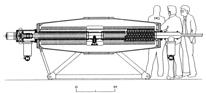
Figure 2.3.1 Photograph of the completed accelerator with the associated power supplies. Three main components comprise the working body of the accelerator and are shown in Figure 2.3.2. Listed in the order in which ions are produced and accelerated toward the target, these components are: (1) the ion-source, (2) the injector, (3) the accelerating column and pressure vessel. Taken collectively these components have a combined weight of nearly 1000 kg. The length of the entire machine from the end of the ion source to the end of the pressure vessel is 3.9m. The largest diameter achieved by the truncated cones which make up the pressure vessel is 0.94 m. Supported by an adjustable aluminum stand which can be moved on rollers, the accelerator has a height of 1.6 m at the highest point on the pressure vessel.
O IM
I I I
Figure 2.3.2 Schematic of the accelerator illustrating the main working components.
2.4 Basic Tandem Accelerator Operation
LABA's tandem electrostatic accelerator is designed to accelerate up to 4 mA of protons
or deuterons and achieve energies of up to 4.1 MeV in order to produce neutrons via the
7Li(p,n)7Be, 9Be(p,n)9B, or the other charged particle reactions. The following is a basic
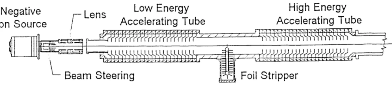
description of the accelerator operation. Figure 2.4.1 illustrates the separate components
as they are oriented within the body of the accelerator. Further details will be provided in
later sections. First, negative ions are produced by a high-current multicusp source.
These ions are extracted at 3 keV and then accelerated to 20 keV as they enter the injector
which incorporates two-orthogonal Wein filters, X-Y steering plates, and an Einzel lens.
Before entering the low energy accelerating tube, the ions are also focused by the fringe
fields of the tube itself. Once inside the low-energy tube, the negative ions are accelerated
high-frequency switch-mode converter coupled to a solid state cascade voltage multiplier
circuit [3]. The ions are stripped of their electrons in the terminal by passing them through
a carbon stripping foil mounted on a stainless-steel holder. Final acceleration occurs in the
second accelerating tube as the now positive ions are accelerated toward ground
potential.
Negative Lens Low Energy High Energy
Ion Source Accelerating Tube Accelerating Tube
Figure 2.4.1 Orientation of accelerator components within the main body of accelerator.
Several innovative technologies have been incorporated into the accelerator
making it feasible to produce the required current at energies which can be used in BNCT
research. The energy of the beam is continuously tunable over the range of 0.5-4.1 MeV.
This fact could be exploited in the investigation of near-threshold reactions of a variety of
neutron-producing targets. In addition, the ion-source and the target structure are at
ground potential outside of the pressure vessel. With this orientation, changes to the
ion-source or modification of the target and neutron moderator are greatly simplified. No
invasion into the pressure vessel or accelerating column is needed to make changes to the
target or moderator. Additional innovations which will be described in the subsequent
negative ion source, and the switch-mode type high voltage generator. The following
sections will describe the individual working of each of the major components of the
accelerator. For clarity, the order in which they are described follows the progression of
the ions through the accelerator from production to exit.
2.5
High-Current Multicusp Negative Ion-Source
Conventional negative ion sources used in tandem accelerators, such as duoplasmatrons or
sputter sources, are unable to provide negative ion currents which are sufficient for
neutron production for BNCT. Maximum outputs of these types of sources is limited to
currents of less than 100ptA [3]. Research in the early 1980's, however, indicated that a
relatively large concentration of negative hydrogen ions were present in the volume of a
hydrogen discharge [4]. Utilizing dissociative attatchment, the multicusp negative ion
source, shown in Figure 2.5.1, was designed to produce up to 5 mA of H- . The
ion-source is 25.4 cm long with a diameter of 18.4 cm. It is joined to the injector with a
compression flange of diameter 30.5 cm.
Production of negative ions begins with the introduction of high purity H2 gas
through the terminal block into the plasma discharge volume which has been evacuated to between 10-7-10-8 torr by a cryogenic pump. Gas flow is facilitated through a digital flow
controller which limits the input of hydrogen to a few cc/min during operation. When the gas is introduced, the pressure inside the chamber is increased to a few milli- torr.
Hyd Hyd Inlel Ter Blo Extraction Electrode
Figure 2.5.1 Schematic of multicusp ion source on LABA accelerator.
The cylindrical plasma discharge volume is separated magnetically into two regions
by ten cobalt-samarium magnets placed around the edge of the water-cooled copper
chamber and held in place by the magnet holder. These magnets are oriented in an
anti-symmetrical fashion so that a high-order multipole field separates the volume into two
regions. The first region extends from the filament end of the source to within a few
millimeters of the extraction aperture. Here, high energy electrons, which are boiled off
the filament and accelerated to approximately 100 eV, interact with the gas to generate
vibrationally excited H2 molecules. It is also possible that these electrons can ionize or
disassociate the H2 molecules. The resultant spectrum of electrons has a Maxwellian
shape with an average temperature of approximately 2 eV.
The tungsten filament is heated to emission temperatures by passing approximately
175A through the filament itself. Once the filament reaches a temperature of 2250 OC,
thermionic emission facilitates the ejection of electrons from the surface. Having been
emitted, these electrons are accelerated toward the body of the chamber which serves as
the anode with a bias of 100 V. Although these electrons are ejected at nearly 100 eV, they are quickly slowed by excitation and ionizing collisions. These ionizations produce a
low energy thermal population of electrons which, along with the hydrogen molecules, can
pass through the magnetic filter and enter the extraction chamber.
In the extraction chamber, hydrogen molecules which have been vibrationally and
rotationally excited through collisions with the walls of the chamber and through collisions
with energetic electrons, are in close proximity to low energy electrons with energies less
than 1 eV. It is here that the fundamental process of dissociative attachment produces
H-ions. Although the discussion of the physics of dissociative attachment is beyond the
scope of this investigation, references [4-6] should be investigated for further information.
The basic reactions which take place in the extraction chamber are
e + H3+ -- HI + H2+ (2.5.1)
e + H2(3Iu) -+ If + H (2.5.2)
e + H2(v*) -+ H- + H (2.5.3)
where H2(3 -Iu) represents a hydrogen molecule in an excited rotational state, and
The extraction electrode draws the HI ions out of the extraction chamber.
Electrons are also drawn out of the plasma discharge along with the negative hydrogen
ions by an electric field applied by the extraction electrode. In order to filter out the
electrons, small magnets are located near the extraction electrode aperture. This electrode
is biased to a few keV. Electrons are deflected by a transverse magnetic field of nearly
100G and collected on the extraction electrode. Experiments indicate that nearly 90% of
the electrons are removed by this magnetic field while the remaining 10% strike the
acceleration electrode [6]. Thus, the beam that is accelerated to nearly 20 keV by the
acceleration electrode consists mainly of H- ions. The beam, which has entered the
injector as it is accelerated to 20 keV, now passes through the injector where it will be
filtered and steered so that it will be directed along the axis of the accelerator.
2.6 The Injector System
Beginning from the acceleration electrode, the components which make up the injection
system include two Wein filters, horizontal and vertical steering plates, and an Einzel lens. The combined effect of these components is to focus and steer the beam so that it is in the correct orientation to enter the accelerating tube. High current ion beams of low energies expand under the influence of space charge forces. This space charge effect degrades the
beam quality. The injector system is designed to minimize the distance from the ion
source to the entrance of the low energy accelerating tube in order to minimize the spreading effect of beam space charge [3]. Since it is possible that heavy ion contaminants
filters produce perpendicular electric and magnetic fields which are transverse to beam
velocity. These fields are adjusted so that for the desired species ie. protons or deuterons, the two fields will exactly cancel, and these ions will pass straight through. Unwanted
heavier ions will be deflected out of the path of the beam. The Wein filters are also used
to steer the H- beam. In order to prepare the beam for injection into the accelerating
tube, an Einzel lens biased to around 4.5 kV is used to focus the beam. As the beam
approaches the entrance to the low energy tube, the fringe fields produce a strong
focusing effect. The total length of the injector system is 0.5 m and its diameter is 30.5
cm.
2.7
Switch-Mode High Voltage Generator
A high-frequency switching power supply is used to provide power to the accelerator
high-voltage terminal. The switching power supply, which can produce up to 12 kW, begins the production of high voltage by generating square wave signals at a certain
voltage level and frequency. Each of the pulses are on the order of hundreds of volts
while the frequency of the pulses are several kHz. Under steady state conditions, these
pulses are uniform in width. The signal from the supply is then sent to a step-up
transformer which is mounted on the end flange of the pressure vessel. Space is
conserved through the mounting of the transformer and multiplier circuit directly to the
accelerator, thereby eliminating the need for an external power chassis [7]. Voltage from
the power supply is stepped up by a factor of 200 in the transformer before it is applied to
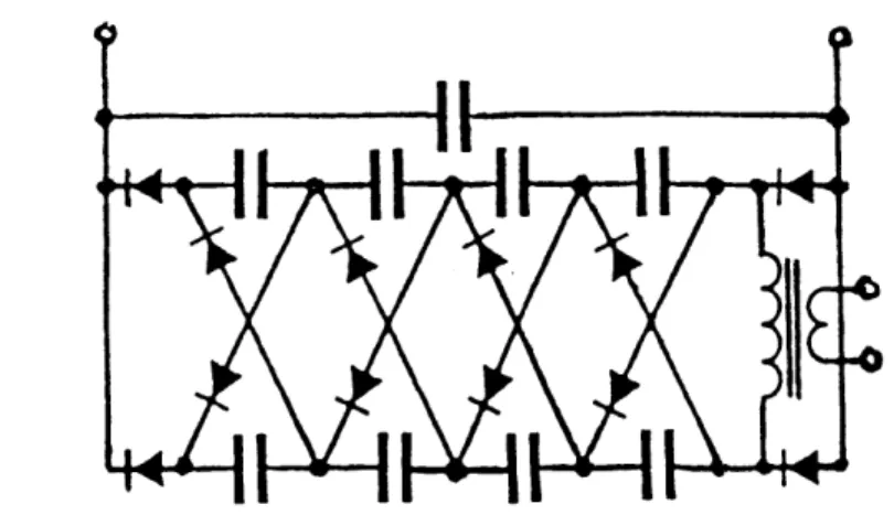
A modified Jones and Waters circuit is employed to produce terminal voltages of
up to 2.05 MV. This circuit, which is diagrammed in Figure 2.7.1, originated in the
Research Laboratories of Associated Electrical Industries Ltd. It was developed to
improve upon the poor characteristics of the Cockcroft and Walton multiplying circuit
[8].
Figure 2.7.1 The modified Hones and Waters circuit employed in the LABA accelerator.
The circuit is divided into two sections which are located on the top and bottom of each
stage on the high-voltage end of the accelerating column. Switching the load from the
top to the bottom sections during each cycle limits the voltage ripple. In each alternate
half-cycle, each capacitor except those at the very top transfer their charge to the one in
the opposite stack [8]. The rectifying nature of the circuit transforms the periodic voltage
pulses from the power supply into a DC signal with a very small voltage ripple. Terminal
voltage is monitored by a high-voltage electric field sensor which is configured to sample
coupled to the power supply to provide feedback. When current is accelerated at
increasingly higher voltages, the terminal becomes loaded, and the voltage will decrease.
This decrease in voltage is detected and returned to the power supply. In response to this
loading, the power supply will maintain terminal voltage by increasing the pulse width of
the switching converter.
2.8 Pressure Vessel and Insulating Gas
The pressure vessel consists of two conical sections joined to a 0.94 m diameter cylinder
section in the middle of the accelerator. The vessel is designed in accordance with the
ASME pressure vessel code. The body of the pressure vessel is constructed of aluminum
with a thickness of 1.6 cm on the conical sections of the tank while the section which
covers the high-voltage terminal has a wall thickness of 5 cm. The flanges at the ends of
the pressure vessel are 5 cm thick and have a diameter of 0.63 m. Attempts to charge the
terminal to voltages higher that 220 kV in air are unsuccessful because of the dielectric
breakdown which occurs at 30 kV/cm at 15 psia. In order to bring the terminal up to 2.05
MV, which is needed to accelerate a proton to 4.1 MeV, the accelerator must be insulated
with pressurized sulfur-hexaflouride (SF6). An empirical relation, listed as Equation 2.8.1, can be used to estimate the limiting voltage achievable under a certain pressurization with
SF6.
Electric Field Breakdown(SF6) = 75 (P/15)0.6 kV/cm (2.8.1)
In order to achieve terminal voltages of 2.05 MV, the vessel has been pressurized to 105 psia. Using the above relation, the point of breakdown is found to be 241 kV/cm. Thus, the insulating gas has improved the achievable voltage by a factor of seven compared with atmospheric air alone. A gas recovery system was also constructed which allows the tank to be emptied and filled without loss of all gas from the vessel. Since SF6 is heavier than air, precautions such as monitoring oxygen levels have been instituted in the lab to protect against asphyxiation due to oxygen displacement.
2.9 Low and High Energy Accelerating Tubes
The ion beam is accelerated by a uniform electric field which is produced by two accelerating tubes mounted with the accelerating column. Aluminum electrodes and glass insulators are alternately stacked in an assembly to form each accelerating tube as shown in Figure 2.9.1.
The accelerating tubes were manufactured by Vivirad High Voltage Corporation in Billerica, MA. To assemble the tube, the aluminum electrodes were machined with an opening for the beam as shown in Figure 2.9.2. A transverse magnetic field is applied at each electrode by a pair of samarium-cobalt magnets to suppress secondary electron production in the accelerating tube. Most tandem accelerators have used inclined electric fields to suppress secondary electron production. Although this has been used successfully at low currents, proton trajectories become unstable at high currents, which leads to an overall loss of current. Magnetic suppression is effected by two magnets positioned on each electrode by a suppression magnet holder. This holder aligns the magnets in such a way as to create a magnetic field perpendicular to the axis of the accelerator. Any electron that is produced within the accelerating tube will be turned out of the beam before it gains sufficient energy to produce energetic bremmstrahlung radiation.
Between each electrode is an annular glass insulator. In order to join successive sections
of the tube, adhesive was applied to the glass, and the electrodes and insulators were
stacked in a jig. This assembly was heated to 160 oC in order to cure the adhesive.
The low energy end of the tube is located between the injection system and the
terminal. No voltage multiplication circuitry is located in this section as is the case on the
high energy side which is between the terminal and the exit of the accelerator. 47 stages
make up the low energy end of the tube, while 52 stages make up the high energy side.
Voltage is distributed to the low and high energy accelerating tube electrodes through a
simple voltage divider circuit which uses 47 and 52 200 MR2 resistors respectively to
connect each of the electrodes. The resultant gradient in each of the tubes is uniform, and
at a terminal voltage of 2.05 MeV the voltage gradients are 17.17 kV/cm for the low
energy tube and 15.52 kV/cm for the high energy tube.
2.10 Carbon Stripping Foils
Negatively charged particles which have been accelerated to an energy qVo in the low
energy side must be stripped of their electrons in the terminal. Two possible methods
have been employed to facilitate the production of positive particles: (1) gas stripping and (2) carbon stripping foils. Gas stripping can handle large currents easily, and there is no chance of damage to the stripping medium. Ionization in the stripping gas does, however, create a secondary load on the power supply. This load can exceed that contributed by the primary beam by several times under acceleration of high current. To avoid this drawback, carbon stripping foils are incorporated in the tandem accelerator at LABA for
production of positively charged particles. These foils are extremely thin (5-10 jig/cm2)
although they strip nearly 100% of the electrons on the incoming particles. Foils are
mounted on stainless steel sleeves with an openings of either 5/8 or 7/8 in. diameter.
These sleeves are held on a rotating platform which can accommodate over 50 foils.
Each foil has a limited lifetime depending on the thickness, beam current, and accelerating
voltage. Predictions of foil lifetimes from 10-100 mA-hours have been developed for
proton beam energies of 1.25-2 MeV [3].
Stripping is the final process in the creation of the charged particle beam before it
enters the second accelerating region. After the beam is accelerated toward ground
potential, it exits the accelerator where it can be focused and steered in order to strike a
target, where it then deposits its energy. This energy is the source of heat which must be
removed in order to keep the target from melting. Removal of this energy is a heat
Chapter 3
HEAT TRANSFER
3.1 Fundamentals of Heat Transfer
Heat transfer involves the movement of energy through a body resulting from a
temperature gradient. Whereas thermodynamics deals with the end states of an energetic
process, the intermediate processes by which heat energy is carried from one place to
another and the rates at which this occurs is the domain of heat transfer. In order to
understand the mechanisms of heat transfer involved in the design of a high-power
accelerator target, the basics of conduction, convection, and radiation must be developed.
Perhaps the simplest form of heat transfer, conduction involves the movement of
heat through a body in which there exists a temperature gradient. Conduction requires
only that a temperature gradient exists in a body. If this body is a gas or liquid, the
movement of the molecules gives rise to a diffusion of energy. Because the hot molecules
have a greater velocity than the colder molecules, there will be a net movement of heat
from a hot region towards a colder region. In a solid, this transfer occurs in much the same way although there are differences in the mechanisms of conductors and insulators.
In conductors the vibration of free electrons and thermal waves within the atomic lattice allows for heat transfer, while insulators allow only lattice waves. Correspondingly, there
is a very strong correlation between the electrical conductivity and thermal conductivity of
materials.
Conduction can be expressed as a rate equation known as Fourier's Law. This
equation states that the heat flux per unit area is proportional to both the thermal
conductance of a material and the temperature gradient. A negative sign indicates that
heat always travels from a hot to cold regions.
q" = -k dt/dx (3.1.1)
q =- Ak dt/dx (3.1.2)
where q": heat flux (W/m2)
k: thermal conductivity (W/m K)
q: heat (W)
A: area of body perpendicular to heat flow (m2)
dt/dx: temperature gradient per unit length (K/m)
While conduction will occur in any body independent of motion, convection
involves both the diffusion of heat and the bulk motion of a fluid. If a surface is in contact
with a fluid which is at a lower temperature, any movement of the fluid will remove heat
from the interface. If this fluid motion is due to flow resulting from an external forcing
mechanism such as a pump, it is referred to as forced convection. Free convection occurs
to the buoyancy forces, the fluid motion gives rise to free or natural convection. As a
rule, forced convection is more efficient than free convection at removing heat. Fluid
motion can also be induced by boiling or condensation. Convection involving a phase
change is even more effective than forced convection. Jet impingement cooling, a subset
of convection, will be investigated in greater detail later in the chapter.
Convection is illustrated by Newton's Law of Cooling which states that the heat
flux due to convection is proportional to a constant (h) and the temperature gradient
between the surface and the fluid.
q" = h (Tf-Ts) (3.1.3)
q = h A (Tf-Ts) (3.1.4)
where h: convective heat transfer coefficient (W/m2 K)
Tf: fluid temperature (K)
Ts: surface temperature (K)
Determination of the heat transfer coefficient will be the primary task of experiments in a
convective system. Once h has been determined, the performance of a cooling system can
be predicted. In order to determine an experimental value for h, three primary properties
of the fluid must be determined. These properties are: temperature, conductivity, and
with fluid velocity. If a phase change is occurring, the latent heat becomes important in
determining h. The definition ofh will be provided in section 3.2.
Radiation is the only heat transfer mechanism which requires no medium in which
to take place. The movement of heat is carried out by electromagnetic radiation primarily
in the visible and infra-red energies. In most applications radiation becomes important
only at high temperatures or in the presence of a vacuum. According to the
Stefan-Boltzman Law, radiative heat transfer can be expressed by:
q" = •o (Ts4 - To4) (3.1.5)
where E: emissivity of the surface
a: Stefan-Boltzman constant
5.67 x 10⁻⁸ W / m2 K4
Too: temperature of surroundings (K)
3.2 Convection
Most heat transfer applications make use of a moving fluid in order to carry away heat
from a surface. As indicated by Equation 3.1.3, the coefficient h must be determined
before the heat transfer capacity of a system can be predicted. Calculation of this
coefficient is central to the study of heat transfer. Many well-known relationships exist
which provide expressions for calculating h under certain conditions. As a rule, these
expressions are good for specific flow geometries within a range of flow parameters.
Nu = Constant Rea Prb
where Nu: Nusselt Number
Re: Reynolds Number
Pr: Prandtl Number
Parameters such as the Nusselt, Reynolds, and Prandtl Number are non-dimensional
relations which are dependent on various coolant properties.
The Nusselt Number is a ratio of the convective to conductive heat transfer in the
cooling fluid at the surface boundary. A value of unity indicates that the fluid is stagnant
and conducting only. As Nu increases, the convection of the fluid improves. Nu can be
expressed as:
Nu = h d / k (3.2.2)
where d: characteristic length or diameter
k: conduction coefficient of fluid
In applications such as jet impingement cooling, d would be the diameter of the jet nozzle.
The Reynolds Number (Re) is simply a ratio of the inertial and viscous forces in a
moving fluid and can be expressed by:
Re = V d / v
where V: fluid velocity (m/s)
v: kinematic viscosity (m2/s)
The final parameter, Prandtl Number (Pr), is the ratio of momentum and thermal
diffusivity. It simply indicates the ability of a fluid to transport energy and momentum in
the thermal and velocity boundary layers [9]. Although this value can be calculated from
inherent fluid properties it is simply a constant dependent only on temperature.
3.3 Determination of h
The determination of h is specific to each geometry and flow pattern. It is also important
to realize that relations such as 3.2.1 are typically good over a very specific range of Re
and Pr. Although approximations for h can be developed by using Nusselt Number
relations derived for similar situations, in order to accurately determine the heat transfer
capability of a system, h must be found for each system. Standard experiments for
determining h are done as follows:
(1) Configure the heat transfer system and flow pattern.
(2) Evaluate the power (q) placed on target.
(3) Measure the temperature of the flow or jet in order to determine fluid properties.
(4) Determine the velocity of the flow or jet in order to calculate Re.
(5) Determine the surface temperature of the target (Ts).
(6) Calculate the area A through which the heat is being transferred.
(7) Use 3.1.4 to determine h.
Once h has been determined for a range of Re and Pr, an expression in the form of 3.2.1
can be developed. This expression can now be used to predict the heat transfer capability
of a similar system within a defined flow regime.
3.4 Boiling Heat Transfer
When a surface covered in liquid becomes hot enough to raise the temperature to the point
where the fluid's vapor pressure is equal to or greater than the surrounding pressure, boiling will occur. This point occurs if Ts exceeds the saturation temperature (Tat) of the
fluid. This temperature excess (Te) is given by Ts - Tst , where Tsat is a function only of
pressure for a specific liquid. Even before boiling begins, heat is being transferred away
from the surface due to the enhanced natural convection of the water. Once boiling
begins, however, heat transfer is greatly enhanced due to the utilization of the latent heat
of vaporization in the boiling process. Pool boiling, which is simply boiling in a stagnant
body of water, can dissipate up to 106 W/m2 before a departure from nucleate boiling
(DNB) occurs.
Departure from nucleate boiling occurs when the heat flux from the surface
vapor blankets the heated surface, and the heat transfer falls by orders of magnitude. The
point at which this occurs is termed the critical heat flux (CHF). If a significant amount
of heat is being deposited in the target when DNB occurs, the target can and will heat up
quickly past the point of failure. In many instances, failure is immediate and catastrophic.
The critical heat flux has been measured for pool boiling and is given in the expression [9]:
q"9max
0.1
4 9hfgpv[ g(P-p P ) 1/4(3.4.1)
where hfg: heat of vaporization (J / kg)
pv: density of vapor (kg / m3)
pi: density of liquid (kg / m3) o: surface tension (N / m)
The above expression holds for a heated surface covered in a layer of stagnant fluid. For
water at 1 atm, CHF occurs when the heat flux exceeds 1.29 MW/ m2. If this fluid is
forced across the surface of the target, the added heat transfer from the convection will
raise the point of CHF past that of pool boiling. Furthermore, if the flow is configured so
that the dynamic pressure on the heated surface is greater than atmospheric pressure, the
saturation point of the fluid will be increased thereby raising the point of CHF. Jet
impingement cooling is perhaps the most effective way to take advantage of all these
3.5
Jet Impingement Cooling
The use of submerged impinging jets has been studied as a means of enhanced heat
transfer in electronic devices, industrial processes, and as an innovative target cooling
mechanism. Under similar heating and coolant conditions, jet impingement is the most
effective flow mechanism for the enhancement of heat transfer. In addition, experimental
evidence suggests that submerged jet impingement is 25% more effective in removing heat
than with free surface impingement [10]. Using a submerged high velocity jet of water
confined in a test assembly, power densities of up to 6 kW/cm2 have been dissipated with
heat transfer coefficients of 106 W/m2 K. Table 3.5.1 indicates relative ranges of various
types of heat transfer coefficients.
Submerged jet impingement involves the injection of an axisymmetric flow of fluid by
means of a nozzle through a region of the same fluid at rest above the target. The jet
entrains fluid from the stationary body as it strikes the target. Upon striking the target
surface, the jet spreads out radially from the area of impact which is termed the stagnation
point. This radial spreading combined with the entrainment of the fluid above the target, keeps the jet at a lower temperature than with forced convection. The fact that a phase
change can also occur allows the removal of heat through the vaporization of the coolant.
This use of boiling substantially improves the effectiveness of submerged jet impingement, but it is extremely important that CHF not be exceeded when boiling occurs.
Table 3.5.1. Ranges of Various Heat Transfer Coefficients [9]
Mechanism Coefficient range (W/m2 K)
Free liquid convection 50-1000
Forced liquid convection 50-20000
Radiation at 1600 K 10-4-105
Convection with phase change 2500-105
Submerged jet with phase change >6x10'
In jet impingement studies, in addition to parameters such as Re and Pr, certain
non-dimensional parameters must also be specified. These are given as ratios in terms the
nozzle diameter.
Z/d: nozzle to target spacing
r/d: radial distance from stagnation point
A/d: target size
Non-dimensional parameters such as Z/D can be altered by changing the size of the
nozzle and by adjusting its position relative to the target.
The fundamentals of heat transfer and the method for evaluating the heat
transfer coefficient which were presented in this chapter, served as a the foundation for
Chapter 4
TARGET DESIGN AND
THEORETICAL CALCULATIONS
4.1 Introduction to Target Design
Development of Accelerator Based Boron Neutron Capture Therapy (BNCT) as a viable
clinical procedure depends on the reliability, compact-nature, and cost effectiveness of an
accelerator to produce an intense source of neutrons. In order to achieve neutron
production on the order of 10'0-102 n/s, low Z metals such as 7Li or 9Be can be
bombarded with multi-milliampere beams of either protons or deuterons at energies of a
few MeV. At these energies, heavy charged particles will be completely stopped within
millimeters or less of the target material, thereby requiring that powers of several kilowatts
be removed. Beryllium was chosen as a target material for initial investigation because of
its thermal, mechanical, chemical, and neutron producing characteristics. This chapter
investigates the potential of submerged water jet impingement as a means of removing in
excess of 10 kW from a neutron producing beryllium target. Design considerations and
theoretical calculations performed during the development of the high-power target are
presented. Figure 4.1.1 and 4.1.2 should be referenced while reading the following
sections. These figures and photographs illustrate the target that was designed for the
1/2" NPT tap Cro -t' 0" 0 CD~ C. rA t) :71 oC 0 -t
)
Beryllium Target
304 Stainless Steel
F77- 7f- l_Beryllium Target Holder
Piece Number One
Dimensions in Inches
I
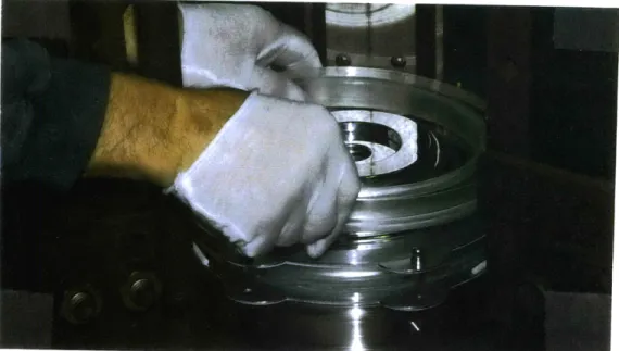
Figure 4.1.2 Photographs of beryllium target. 43
4.2 Target Requirements for BNCT
Production of neutrons can be accomplished by bombarding a low Z material such as
lithium or beryllium with protons or deuterons. Example yields are shown below in Table
4.2.1.
Table 4.2.1 Some typical neutron producing reactions proposed for BNCT [2].
REACTION OUTPUT BEAM ENERGY
7Li(p,n)7Be 8.97x10"n/s-mA 2.5 MeV
9Be(p,n)9B 5.25x10'1n/s-mA 4 MeV
9Be(d,n)'OB 1.0x10¹²n/s-mA 2.6 MeV
For each reaction, it is estimated that currents between 2.5-4 mA will be needed in order
to make therapy times reasonable [2]. This translates into as much as 10-16 kW of power
that must be removed from the target. If the beam is spread over a 15 cm2 area, the
power density would be around 1 kW/cm2. Normally, however, the beam is made to
cover an area of approximately one-half the total target area making the local power
densities on the order of 2 kW/cm2. Removal of heat fluences on the order of 2 kW/cm2 is difficult with forced convection, even when a phase change of the coolant is utilized.
Rrelations developed by Eichhorn and Lienhard [11] for forced convection with a phase
change indicates that even with a flow of 35 m/s across a tube with a diameter of 0.87"
only 1.5 kW/cm2 can be removed. In order to design a practical target that can be used
material must be able to withstand high heat loads while maintaining good thermal
conductivity.
4.3 Target Material Properties
The two most promising target materials from a neutronic standpoint are lithium and
beryllium. Lithium, in fact, is the better choice neutronically because the energy spectrum
of the emitted neutrons is softer thereby requiring less moderation. It fails to be a good
target choice from a thermal and mechanical standpoint. Table 4.3.1 indicates the relevant
thermal and mechanical properties of beryllium and lithium.
Table 4.3.1 Mechanical and thermal properties of typical BNCT target materials [12].
Melting Point
(oC)
1286 180.5 Conductivity (W/m K) 210 84.7Yield Strength (Pa)
260x1 06 small
Interestingly, beryllium maintains a large yield strength at high temperatures. Even at
temperatures in excess of 600 'C, the yield strength is approximately 100 MPa [13].
Lithium is not only a poor thermal conductor, but its explosive reactivity with
water makes engineering of a cooling system which uses water as the working fluid
difficult. Because of its poor conduction, use of lithium targets has typically been limited
to lithium oxides or thin layers deposited on a copper substrate. These targets are
disadvantageous because not only do they replace a large mass fraction of lithium with
I Beryllium
other non-neutron producing elements, but they also suffer from significant sputtering
effects when bombarded by energetic beams.
Because of its strength, conductivity, and neutron producing capability, beryllium
was chosen as the target material for the high-power target. The one difficulty that is
encountered with the beryllium target is the machining. The dust of beryllium is extremely
toxic, and machining can only be carried out by certified individuals. All machining for
this target was carried out by Brush-Wellman.
4.4 Target Radius and Thickness
There are two basic requirements for the size of the target. The first is that its radius and
thickness should be large enough so that a beam can be spread over as much of the
available area as possible providing that the entire beam strikes the target without scraping
the beam tube. The second is that the target be mechanically sound even under extreme
operating conditions. It was noted earlier that up to 16 kW of power could ultimately be
deposited on the target. In order to provide a large target surface area, the beryllium was
constructed with a diameter of 1.75" resulting in an area of 15.52 cm2. Conveniently, this
diameter is slightly less than the 1.85" ID of a standard KF-50 flange.
The thickness of the target is dependent on the pressure that will be exerted on the
target, and the range of the bombarding particles. For a beam of 4.1 MeV, heavy charged
particles have a range of between 10-20 mils. The pressure considerations, therefore, were the main criteria for choosing a target thickness. In order to calculate the thickness
S = 0.25(E p2a2/ t2)1/3
where: S: maximum stress on the target (psi)
E: Young's Modulus (psi)
p: pressure (psi)
a: radius of target (in.)
t: thickness of target (in.)
Considering a beryllium target at 650 'C with a 1.75" diameter under vacuum and being
struck on one side with a jet of water at 35 m/s, the thickness needed was calculated to be
0.76". This is an extremely conservative measurement since the tensile strength of
beryllium is as much as a factor of two higher at operating temperatures of a few hundred
degrees Celsius [13]. Under normal operation of the target, the beryllium would be held
at only a few hundred degrees Celsius. The only time that the target might approach 650
'C, would be under extreme heat loads of several kW/cm2. For an added measure of safety, the target was designed with a thickness of 0.1"
4.5
Target Design Considerations
Taking advantage of the simplicity and efficiency of jet impingement cooling, the
high-power target was designed to have a single jet strike the back of the target at high velocity (4.4.1)
in order to remove the heat. From the beginning, the target was designed to remove up to
6 kW/cm2. With a target area of 15.5 cm2, the =90 kW that could be removed from the
target, would be more than sufficient for BNCT.
Two primary references were consulted in order to serve as a basis for the
high-power design. A Soviet experiment by Maceika and Skema indicated that heat fluxes as
high as 6 kW/cm2 had been dissipated by a 18 mm diameter submerged nozzle at a cooling
flow rate of 35.3 m/s [15]. Results from these experiments also suggested that the
optimum diameter for the cooling nozzle was V2 that of the area being cooled. The target, therefore, was designed to allow nozzles of various diameters (0.1-0.87") to be tested.
The second reference by Garimella and Rice indicated that the optimum Z/D
spacing would be found typically between 1-5 [16]. In fact, all experiments conducted by
Garimella and Rice and in this work indicated that the optimum Z/D spacing was normally
1. Reasoning for this conclusion is that it is desirable for the potential core to strike the
target after it is well developed. Past a Z/D of 5, the core has begun to deteriorate, whereas before 1 Z/D the core is still suffering from nozzle exit effects.
4.6 Target Cooling Estimations
As mentioned in Chapter 3, boiling can serve to increase the convective heat transfer
coefficient. For target design, however, it is necessary that the point of CHF be known
since any type of burnout while on the accelerator would have catastrophic results. For
the target constructed in this work, the following calculations were used to estimate the
One of the most basic estimates of the heat removing capabilities of water is a
control volume calculation. A control volume cconsiders only the energy entering a
specified volume and the energy leaving. The difference in the amount that enters and
leaves must be deposited or generated in the control volume. For this example, radiative
losses have been neglected due to the low temperature of the target. Using the control
volume approach:
qmax = m cp ATcoolant (4.6.1)
where m: mass flow rate (kg/s)
cp: specific heat (J/kg oC)
ATcoolant: temperature rise in cooling fluid
For a relatively large beam which covers the majority of the target, the heat flux (W/m2 K)
is simply
q" = q / Atarget (4.6.2)
The same argument can be used to relate the temperature increase in the coolant to the
temperature distribution in the target wall. Under steady state