A Case Study of a Product Architecture
EARKER
by
OF J TSINT j '"T ECH NOLOGY
Thomas Hughes Speller, Jr.
B.S., Economics, Chemistry and Psychology
Ohio University, 1972
LIBRARIES
MBA, Finance and Marketing
University of Chicago, Graduate School of Business, 1974 Submitted to the System Design and Management Program in Partial
Fulfillment of the Requirements for the Degree of
MASTER OF NGINEERING AND MANAGEMENT
at the
MASSACHUSETTS INSTITUTE OF TECHNOLOGY
December 2000
0 2000 Massachusetts Institute of Technology. All rights reserved.
The author hereby grants to MIT permission to reproduce and to distribute publicly paper and electronic copies of this thesis document in whole or in Dart.
Signature of Author...
z
...
,System Design and Management Program
December 18, 2000
Certified by...
...
Dr. Daniel E. Whitney Senior Research Scientist Center for Technology, Policy, and Industrial Development A ccepted by ...
Steven C. Graves Abraham Siegel Professor of Management LFM/SDM Co-Director
Accepted by ... ...
Paul A. Lagace Professor of Aeronautics & Astronautics and Engineering Systems
MITLibraries
Document Services
Room 14-0551 77 Massachusetts Avenue Cambridge, MA 02139 Ph: 617.253.2800 Email: [email protected] http://Iibraries.mit.edu/docsDISCLAIMER OF QUALITY
Due to the condition of the original material, there are unavoidable
flaws in this reproduction. We have made every effort possible to
provide you with the best copy available. If you are dissatisfied with
this product and find it unusable, please contact Document Services as
soon as possible.
Thank you.
The images contained in this document are of
the best quality available.
Thomas Speller, Jr. MIT No. 920016172 A Case Study of a Product Architecture
(This page intentionally left blank)
Thomas Speller, Jr. MIT No. 920016172 A Case Study of a Product Architecture
Product Architecture
A Case Study
by
Thomas Hughes Speller, Jr.
Submitted to the System Design and Management Program in Partial Fulfillment of the Requirements for the Degree of
Master of Engineering and Management
Abstract
The primary purpose of this thesis is to document the product design and development of the first product family at General-Electro Mechanical Corporation (GEMCOR), an automatic fastening producer for aerostructure assemblies. The thesis serves both as a case study for academics as well as a model by which the company should conduct further successful product developments. It is quite a remarkable and nontrivial occurrence in the history of the corporation that a product family should be created with extensibility, to encompass new technologies for competitive advantage in addition to covering the entire commercial airplane market automatic fastening requirements for the foreseeable next ten years. Heretofore, the products developed have appeared similar from a distance, but in fact they were not products; instead they were individual prototypes which had certain similarities. The study goes on to show how the world economic influences, competing technological trajectories, the customer supply chain, competition, and organization structure and policies shape the system architecture of the products developed in an extensible product family. This first product development described in this thesis is to serve as the model to follow for Gemcor's future product developments.
Thesis Advisor: Daniel E. Whitney, Ph.D.
Senior Research Scientist
Center for Technology, Policy, and Industrial Development
LFM/SDM Co-Director: Steven C. Graves
Abraham Siegel Professor of Management
LFM/SDM Co-Director: Paul A. Lagace
Thomas Speller, Jr. MIT No. 920016172 A Case Study of a Product Architecture
Acknowledgements
The author would like to thank Dr. Daniel Whitney for his very helpful advisory assistance in this project; Kerstin Speller for her editorial comments and support as well as to my entire family for their patience during the entire System Design Management Program. Further, I wish to express my gratitude to the
entire SDM/LFM1 Program Staff for allowing me to extend the boundaries of my knowledge and career
path by permitting me to attend the finest engineering school in the world, MIT, and to Providence in giving me the ability to do so.
The author considers manufacturing as a subset of the enterprise system and therefore has preceded LFM with the SDM.
Thomas Speller, Jr. MIT No. 920016172
A Case Study of a Product Architecture
Table of Contents
A BSTRA CT ... 3
A CKN OW LED GEM ENTS... 4
TABLE O F CON TEN TS... 5
LIST O F FIGURE S... 8
LIST O F TABLES... 9
LIST OF EXI BITS... 9
APPENDIX ... 10
SECTION 1 INTR ODU CTION ... 11
SECTION 2 A BUSINESS DESCRIPTION OF GEMCOR ... 13
HISTORY ... 13
Gemcor's mission = vision is: ... 13
Corporate Financial Objectives ... 14
STRATEGY DEVELOPM ENT FOR FUTURE DIRECTION... 15
Assembly Automation: Industries Served (Future Market Segment Potential) ... 15
Complementary Assets... 16
Core Technologies (Knowledge in Which Gemcor Must Always Stay Current) ... 16
SECTION 3 TECHNOLOGICAL FACTORS AFFECTING THE STRATEGY FOR GEMCOR 18 SAFETY AND EFFICIENCY ... 18
DESIGN FOR M ANUFACTURING AND ASSEMBLY (DFM A) ... 19
HIGH VELOCITY M ACHINING... 19
MATERIALS INFLUENCING FUTURE DESIGN AND BUILD OF COMMERCIAL AIRCRAFT ... 20
THE INFLUENCE OF JOINING TECHNOLOGIES... 24
NEW TECHNOLOGY FASTENERS... 25
Composites Can Reduce Use of Fasteners ... 25
M OTION CONTROLS ... 25
INFORMATION TECHNOLOGY INFLUENCE ... 26
CONVERGENCES ... 26
CONCLUSIONS ... 27
PLANNING FOR THE FUTURE - OR - ANTICIPATING THE FUTURE... 27
The Trajectories and Evolution of Mechanical Fasteners Used in Commercial Aircraft ... 27
The Recommended Technology Strategy for Gemcor (Opportunity Space for Technological Change Improvements) ... 29
SECTION 4 INDUSTRY TRENDS AND DEMOGRAPHICS AND THEIR EFFECT ON GEM CO R ... 31
STATE OF THE AEROSTRUCTURES INDUSTRY ... 31
ECONOMIC INFLUENCES... 31
Regional Economies ... 32
Commercial Aircraft M arket Economics and Forecast... 33
GEOPOLITICAL CONSIDERATIONS AND THEIR EFFECTS ON THE FUNCTIONAL REQUIREMENTS OF THE VLTA... 34
Thomas Speller, Jr. MIT No. 920016172
A Case Study of a Product Architecture
COMPETITIVE INFLUENCES ... 37
C om p etitive M arket Sp ace... 3 7 A Comparative Analysis of Boeing and Airbus... 38
The Boeing Commercial Airplanes Group... 38
A irb u s In du strie ... 39
Airbus Product Family Profile ... 40
A Potential Threat to Airbus Industrie's Business Growth... 40
AIRCRAFT INDUSTRY FORECAST... 41
Traffic Growth, Airlines and World Aircraft Fleet... 41
Boeing's Forecast and Assumptions ... 42
The Airbus Global Market Forecast and Assumptions... 42
Future Scenarios Which Could Affect Forecasts; Conjectures About Their Impact... 43
N eed
for a N ew A ircraft...
44M a rket N eed ... 4 5 SECTION 5 COMPETITOR ANALYSIS ... 49
THE COMPETITIVE SPACE ... 49
B axi and B rotje ... 49
Comparison of Gemcor to Brotje ... 50
STRATEGICAL CONSIDERATIONS ... 54
F ra n c e ... 5 4 F ix tu rin g ... 5 5 Escrst T Market Introduction with Respect to Competition... 55
SECTION 6 DESCRIPTION OF AUTOMATIC FASTENING SYSTEMS... 56
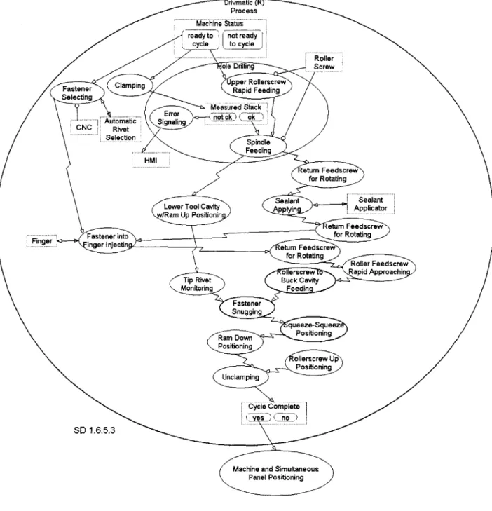
THE DRIVMATIC@ PROCESS ... 56
SECTION 7 FUNCTIONAL DERIVATION OF AN ESCRSTrM AUTOMATIC FASTENING SYSTEM... 62
CREATION AND EVOLUTION OF A NEW PRODUCT FAMILY OF AUTOMATIC FASTENING SYSTEMS FOR A ERO STRU C TU R ES ... 62
Up stream Influencers: ... 62
Downstream Influencers: (Allfunctions were represented as members of the Integrated Product Team in concept and design creation): ... ... 66
DESIGN STRUCTURE MATRIX (DSM) USAGE FOR AUTOMATIC FASTENING SYSTEM: THEORETICAL FUNCTIONAL GROUPING AND DESIGN ... 74
Functions, Inputs and Outputs... 74
M ajor A rch itectures... 85
SUPPLY CHAIN IMPLICATIONS ... 85
SECTION 8 BUILDING A PRODUCT DEVELOPMENT ORGANIZATION... 89
PRODUCT DEVELOPMENT PROCESS IMPROVEMENTS ... 89
Teams, Group Incentivization and Determining Team Division for Product Development... 91
NEW PRODUCT/ MARKET MATRIX ORGANIZATION DESIGN ... 93
THE EVOLUTION AND IMPROVEMENT OF GEMCOR'S ORGANIZATIONAL STRUCTURE... 97
C O N C LU SIO N ... 9 8 SECTION 9 A MODEL OF SUSTAINING CORPORATE GROWTH FOR GEMCOR...111
THE ENTERPRISE IN THE LARGE... 111
THE ASSUMPTIONS OF THE SEPARATE BUSINESS UNITS (SBU's) IN THE MODEL ... 111
D evelop m ent of the M odel... 112
MODEL-DERIVED POLICY DEVELOPMENT... 119
Thomas Speller, Jr. MIT No. 920016172
A Case Study of a Product Architecture
Inflection Points... 119
CRITICAL BALANCES AND RATES OF CHANGE ... 119
C a s h ... 1 1 9 Growth Rate of SBU1 vis-ed-vis SBU2 (Service must keep up with products requirements alignment) ... 1 2 0 Customer Satisfaction... 121
Infrastructure... 122
Risk and Change Aversion... 123
O rd er W in R a te ... 12 3 Adherence to Diversified Portfolio Theory... 123
EVA M easurement and Incentive System... 124
T r u th ... 1 2 4 CONCLUSIONS DERIVED FROM THE M ODEL ... 124
SECTION 10 SUM M ARY AND CONCLUSIONS... 125
SECTION 11 A NORMATIVE APPROACH TO SYSTEM ARCHITECTURE CONCEPT DEVELOPMENT IN PRODUCT DEVELOPMENT ... 128
NATURE'S VARIED PROCESSES OF CREATION, FUNCTION AND FORM ... 132
FUNCTION AND FORM ALTERNATIVES... 136
THE QUANTUM ALGORITHM FOR DETERMINATION OF THE BEST CONCEPT ... 140
THE INTRODUCTION OF GENETIC METHODS TO THE QUANTUM COMPUTATION ... 142
THE ALGORITHM OF THE NORMATIVE SYSTEM ARCHITECTURE...143
Thomas Speller, Jr. MIT No. 920016172 A Case Study of a Product Architecture
List of Figures
FIGURE 3.1 JOINING AUTOMATION TECHNOLOGY ... 18
F IG U R E 3.2 F M L L A M IN A TIO N S ... 22
FIGURE 3.3 FML CRACK STOPPING CHARACTERISTIC... 22
FIGURE 3.4 TECHNOLOGY TRAJECTORIES AND EVOLUTION - MECHANICAL FASTENERS... 28
U SED IN C OM M ERCIAL A IRCRAFT ... 28
FIGURE 3.5 TECHNOLOGY TREND - MECHANICAL FASTENER ELIMINATION IN COMMERCIAL AIRCRAFT ... 2 8 FIGURE 3.6 COMPOSITES - MANUFACTURING OPPORTUNITY SPACE FOR TECHNOLOGY IMPROVEMENTS ... 2 9 FIGURE 3.7 DEVELOPING COMPOSITE STRUCTURE MANUFACTURING AUTOMATION SYSTEM SOLUTIONS TO A ER O SPA C E W A N TS ... 30
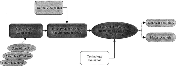
FIGURE 3.8 GEMCOR'S PRODUCT DEVELOPMENT PROCESS [BASIC] ... 30
FIGURE 4.1 C OM PETITIVE M ARKET SPACE... 38
FIGURE 4.2 A DESCRIPTION OF COMPETITOR'S STRENGTHS, WEAKNESSES AND PRODUCTS... 41
FIGURE 4.3 KEY PARAMETERS OF A NEW AIRCRAFT... 45
FIGURE 4.4 BUSINESS CASE ANALYSIS METHODOLOGY FOR COMMERCIAL AIRCRAFT IMPACT ON G E M C O R ... 4 6 FIGURE 4.5 THE MARKET POTENTIAL 2000 TO 2002 FOR AUTOMATIC FASTENING SYSTEMS... 48
FIGURE 5.1 WORLD MARKET SHARE ANALYSIS FOR AEROSPACE AUTOMATIC FASTENING SYSTEMS .... 49
FIGURE 6.1 TYPICAL FASTENER GEOMETRIES INSTALLED AUTOMATICALLY BY THE AFS ... 56
FIGURE 6.2 THE BASIC AUTOMATIC FASTENING CYCLE... 57
FIGURE 6.3 THE Two PIECE FASTENER AUTOMATIC FASTENING CYCLE ... 57
FIGURE 6.4 THE SLUG FASTENER AUTOMATIC FASTENING CYCLE... 58
FIGURE 6.5 THE SQUEEZE-SQUEEZE SLUG FASTENER ... 58
A UTO M A TIC FA STEN IN G C Y CLE ... 58
FIGURE 6.6 THE SQUEEZE-SQUEEZE SLUG FASTENER AUTOMATIC FASTENING CYCLE OBJECT PROCESS D IA G R A M ... 59
FIGURE 6.7 THE OBJECT PROCESS DIAGRAM OF THE AUTOMATIC FASTENING SYSTEM (AFS) FOR C OM M ERCIAL A IRCRAFT A SSEM BLY ... 60
FIGURE 6.8 OBJECT PROCESS DIAGRAM OF THE MULTIFLEXTM AUTOMATIC FASTENING SYSTEM ... 61
FIGURE 7.1 GOALS DECOMPOSITION, GEMCOR CORPORATE (HIGHER LEVEL) AND THE ESCRSTTM PRODUCT FAM ILY (LOW ER LEVEL)... 64
F IG U R E 7.2 E SCRSTTM M O D EL ... 73
FIGURE 7.3 ESCRSTTm FUNCTIONAL DECOMPOSITION DERIVED FROM EXHIBIT 7-6 AND 7-7 ... 79
FIGURE 7.4 AUTOMATIC FASTENING SYSTEM ZOOM IN... 80
FIGURE 7.5 COMPARISON OF THE LINEAR STYLE TO THE ROTARY DESIGN ... 82
FIGURE 7.6 A COMPARISON OF THE HYDRAULIC TO THE ESCRSTTM OPERATION SEQUENCE TIMING C H A R T ... 8 2 FIGURE 8.1 TEAM LEADER AS BOUNDARY MANAGER...93
FIGURE 8.2 INFORMATION FEEDBACK LOOP AND BOUNDARY MANAGEMENT CONDITIONS... 93
FIGURE 8.3 ESCRSTTM PRODUCT DEVELOPMENT TEAMS... 94
FIGURE 9.1 ORDER GROWTH OF SBU
1
... 112FIGURE 9.2 O RDER G ROW TH OF SB U 2 ... 113
FIGURE 9.3 PRODUCT DEVELOPMENT LOOP ADDED TO SBU1 ... 113
FIGURE 9.4 SBU1 AND SBU2 SYNERGISM VIA SUCCESSFUL ORDER FULFILLMENT... 114
FIGURE 9.5 S-CURVE PATTERN OF NEW PRODUCT INTRODUCTION TO THE MARKETPLACE ... 115
FIGURE 9.6 WOM MARKET PENETRATION OF A PRODUCT ... 115
FIGURE 9.7 INITIAL INTERCONNECTION OF THE PRIMARY LOOPS ... 117
FIGURE 9.8 A M ORE SIM PLIFIED M ODEL... 118
Thomas Speller, Jr. MIT No. 920016172
A Case Study of a Product Architecture
FIGURE 9.9 THE DYNAMICS OF THE WORKFORCE, CAPACITY, INVENTORY AND DEMAND IN THE
E N T ER PR ISE S Y ST EM ... 12 1 FIGURE 9.10 THE DYNAMICS OF BUILDING A SKILLED WORKFORCE (I.E., SBU2 SERVICE WORKFORCE)
... 12 1
FIGURE 11.1 T HE C REATIV E PROCESS... 128
FIGURE 11.2 PARAMETER DIAGRAM OF THE QUANTUM VIRTUAL REALITY GENERATED NORMATIVE C ONCEPT, SYSTEM A RCHITECTURE ... 130
FIGURE 11.3 FORM AND FUNCTION (F-F) FLOW DIAGRAM USING OBJECT-PROCESS METHODOLOGY. 131 FIGURE 11.5 VARIOUS TYPES OF SYSTEM ARCHITECTURES THE VIRTUAL REALITY QUANTUM G EN ERA TO R M U ST SO LV E ... 141
FIGURE 11.6 THE ALGORITHM OF THE NORMATIVE SYSTEM ARCHITECTURE OBJECT-PROCESS DIAGRAM ... 14 5 FIGURE 11.7 THE EVOLUTION EMULATION AND THE INTENT SPECIFICATION UNFOLD OBJECT-PROCESS D IA G R A M ... 14 6 FIGURE 11.8 FURTHER DEPICTION OF THE NORMATIVE SYSTEM ARCHITECTURE OBJECT-PROCESS D IA G R A M ... 14 7
List of Tables
TABLE 4-1 EUROPEAN AERONAUTIC AND DEFENSE, N.V...36TABLE 5-1 COMPARISON OF COMPETITION ... 54
TABLE 7-1 ESCRSTTM ROTARY HEAD VIS-A-VIS HYDRAULIC LINEAR HEAD FEATURE COMPARISON .... 81
TABLE 7-2 ESCRSTTM VS. LVEMR...83
TABLE 7-3 THE COMPARATIVE CHARACTERISTICS OF ESCRSTTM TO OTHER PROCESSES... ... 83
TABLE 7-4 PLANETARY ROLLER SCREWS VS. OTHER LINEAR MOTION TECHNOLOGIES ... 84
TABLE 7-5 ESCRSTTM RETURN ON INVESTMENT VS. OTHER PROCESSES STUDIED ... 84
List of Exhibits
EXHIBIT 7-1 SYSTEM ARCHITECTURE ... 63EXHIBIT 7-2 CUSTOMER SUPPLY CHAIN AND SYSTEM ARCHITECTURE NEEDS HIERARCHY ... 65
EXHIBIT 7-3 QUALITY FUNCTION DEPLOYMENT ESCRSTTM ... 69
EXHIBIT 7-4 ESCRSTTM ROBUSTNESS TESTING AND PRODUCT DEVELOPMENT ... 71
EXHIBIT 7-5 DESIGN STRUCTURE MATRIX OF AN AUTOMATIC FASTENING SYSTEM... 76
EXHIBIT 7-6 THE FUNCTIONAL MATRIX HAS HIGHLY COUPLED FUNCTIONS, SOME OF WHICH CAN BE G ROUPED FOR M ODULARITY ... 77
EXHIBIT 7-7 THE RESULTING DESIGN STRUCTURE MATRIX ... 78
EXHIBIT 7-8 CURRENT ARCHITECTURE (UPPER) AND NEW PLATFORM AND MODULAR DESIGN (LOWER) ... 8 7 EXHIBIT 7-9 FUSELAGE AUTOMATIC FASTENING SYSTEM (C-FRAME STYLE)...88
EXHIBIT 7-10 M ULTIFLEXTm ... 88
EXHIBIT 7-11 M ULTIFLEX II M ... 88
EXHIBIT 7-12 FUSELAGE AUTOMATIC FASTENING SYSTEM (NO C-FRAME STYLE)...88
EXHIBIT 7-13 WING AUTOMATIC FASTENING SYSEM...88
EXHIBIT 7-14 VERTICAL WING AND SPAR AUTOMATIC FASTENING SYSTEM WITH OR WITHOUT INTEGRATED FIXTURING ... 88
EXHIBIT 8-1 TASKS PRESORTED AND SORTED BY ORGANIZATIONAL FUNCTION... 99
EXHIBIT 8-2 PRE-OPTIMIZED DESIGN MATRIX STRUCTURE ... 100
EXHIBIT 8-3 OPTIMIZED DESIGN MATRIX STRUCTURE... 101
Thomas Speller, Jr. MIT No. 920016172 A Case Study of a Product Architecture
EXHIBIT 8-5 THE PAST PRACTICE DEVELOPMENT CYCLE ... 103
EXHIBIT 8-6 THE PAST PRACTICE DEVELOPMENT CYCLE CASH FLOW ... 104
EXHIBIT 8-7 THE PAST PRACTICE DEVELOPMENT CYCLE CALCULATION SHEET USING 20% COC .. 105
EXHIBIT 8-8 MARKET CENTERED MULTIPROJECT MATRIX ORGANIZATION...106 EXHIBIT 8-9 FRAMEWORK OF COMPREHENSIVE UPSTREAM CONSIDERATIONS BEFORE BEGINNING THE
ARCHITECTING PROCESS (FUNCTION-CONCEPT-FORM): A CHECK LIST ... 107
Appendix
Appendix to Section 9: Model Variables, Equations and Units ... 150
Thomas Speller, Jr. MIT No. 920016172
The Reason and Purpose of the Thesis Section 1
Section 1
Introduction
This study provides a description of the factors leading to the development of a new product line and the design of an organizational structure to support this first of expected many product families. The intent is to apply the core competencies of our company toward sustaining corporate growth with a positive economic value added in perpetuity using product development as the fuel.
It can be an exciting and yet anxiety arousing experience for a company to give birth to a new product line. The economic and psychological pressures can be great hurdles in the path of any successful product development. The development described herein actually required a different paradigm and almost radical departure from the company's historical way of doing business and probably would not have happened without senior management leading the breakaway from the past. The difficulty of product development cannot be fully appreciated until one experiences the entire life stages from the creation of the idea through its market acceptance. In some cases members of the original team must be replaced once or twice until success is ultimately achieved. Often new products do not make it to the market because of a lack of perseverance by upper management, a lack of funding, or a reluctance by the marketplace to accept the new product idea. The inventors and patent holders sometimes do not receive the fruits of their ingenuity and labors, which instead are garnered by later management, but inventors often do not have the marketing personality or organizational wherewithal to bring their ideas to the market. It is well documented that organizations from modest to large size develop an inertia, a resistance to change, which stifles innovative thinking and risk-taking for the long-term survival corporation. New product development is a risky business. It is an adventure technically, socially, and economically for the
corporation. Efforts in the wrong market direction or even wrong timing -- introducing a product
prematurely, can have devastating and life-threatening effects on a corporation and its leaders, such as happened in the cases of Iridium and the Apple Newton.
Gemcor, General-Electro Mechanical Corporation, created the field of automatic fastening in commercial airframe structures, opening up as a design-manufacturing company in 1936. It took from the late 1940s until the 1970s for the market to recognize the full importance of this branch of assembly automation with respect to the quality improvement of airframe structures, coming in the form of increased fatigue life and joint strength as well as improved product throughput and cost savings. As customers abhor a single source of supply, or supply chain dependence, due to concerns about overpricing and lack of timely responsiveness from the supplier, customer induced competition eventually appeared. Gemcor's continued existence was threatened by a combination of regional competition and a new technology which might substitute for the company's hydraulic, servo based, automatic fastening systems. As a consequence, Gemcor's development efforts worked for two years on alternative electromagnetic riveting systems without any real product breakthrough. Then following a serendipitous discussion session, a superior solution was conceived but in the form of an all electric system to serve as the base technology upon which to build a modular, significantly lower cost, and flexible product line.
This thesis describes where the company was before this technological groundbreaking, the key technological factors influencing the product development, market factors, the competition, the functionality and architecture of the automatic fastening system, the new organizational structure required, and core competencies needed for now and the future.
Many companies do not have the capital resources to simultaneously pursue different product family developments. The time-to-market and investment payback period is normally several years. An
Thomas Speller, Jr. MIT No. 920016172
The Reason and Purpose of the Thesis Section
1
alternative approach was studied using system dynamics modeling to derive a system behavior for identifying market opportunities in the same, similar or different market segments based on the core competencies of a corporation in developing new products. Using this model, a paradigm was created for product development and product portfolio expansion requiring modest initial capital funding while mitigating risk.
Thomas Speller, Jr. MIT No. 920016172
A Business Description of Gemcor Section 2
Section 2
A Business Description of Gemeor
History
Gemcor was incorporated in 1936 as a design and welding company particularly catering to the airframe production market which was mostly located at that time in Buffalo, New York. During WWH riveting
was manually done worldwide - Rosie the riveter. In Buffalo, NY, where considerable fighter and
bomber aircraft production took place, Gemcor developed gang squeezers which clamped, pressed, and squeezed simultaneously several rivets in panels to save time. In 1948 the Drivmatic@ process was invented and developed by Gemcor.
The Drivmatic@ automatic riveting process substantially improved quality, fatigue life and joint strength of airframes. It created a niche market by providing automatic fastening machines and associated automatic part and machine positioning systems. This process has gone through technical evolution in speed and precision. The design of commercial aircraft today is wholly dependent on this automation process, which has resulted in substantially reduced aircraft weight and cost. The most important improvement in these affected airframe designs has been the wing structure due to a novel Gemcor fastener design complemented by a required automated installation process. Today Gemcor has over 70% market share worldwide in this niche market and has just introduced a new, all electric, modular product line which can be configured to suit the customer's wants. This new product is more robust, easier to
operate and maintain, lower cost, and much quicker to produce.2
A holding company, Gemcor Systems Corporation (GSC), was formed to diversify the company. In addition to this first product development, it created the now highly profitable Gemcor Service Support Technologies (GSST), which is intended to be a growth business in service support of Gemcor's already installed product base, for installations of new Gemcor products, and for provision of spare parts. GSST is also chartered to develop its own core competencies and diversify its growth based on these competencies.
The company's size depends on backlog and in 1998 was 250 employees with annual sales of $35 million with a production rate of fifteen systems per year excluding the spare parts and service business. In 1998 after considerable internal and external discussions concerning the soul searching subject of who we are as a company and organization of people, review of the work we have accomplished in the past, and profoundly what is our purpose and mission, we have chosen the multifaceted global industry of automatic assembly. (See heading "Assembly Automation: Industries Future Market Segment Potential" further on.) The summary of this investigation is provided below.
Gemcor's mission = vision is:
To be the best in the world in aerostructure assembly automation, providing value to our customers. Execute this with excellence in customer satisfaction plus one, providing opportunities for growth and security to all our stakeholders.
Thomas Speller, Jr. MIT No. 920016172
A Business Description of Gemcor Section 2
Corporate Financial Objectives
Highly positive economic value added (+EVA) with a cost of capital hurdle rate of 15%, highly positive revenue growth, and highly positive net cash flow.
Gemcor's Current Core Competencies
A company successfully evolves by basing its activities on its core competencies and technologies which constitute competitive superiority. The following list identifies Gemcor's primary skill assets.
* Motion Controls (application)
* Valves
* Motors
* Actuators
* Position Feedback Devices
* Computer Controls
* Data Bus Systems
* Operating Software
* Drivers
* Human Machine Interface (HMI's)
* Displays
* Mechanical Application of Motion Controls
* Fastening Process Development
Servo positioning and upset technology
* Metal Forming * Aluminum * Titanium * Fastener forming * Fastener installation * Processes * Cold
formin
0 Squeezing * Roll forming * Metal spinning* Press brake forming
* CNC punch press
* Laser cutting
* Welding
Fastening of Wing and Fuselage Assembly
Ability to Consistently Provide Customers with Value
* Provide solutions for automatic riveting applications
* Airframe structural design for automatic fastening
* Airframe structural design
* Joint design
* Type of joint
* Type of fastener
* Type of installation process
* DFMA for our customers
3 Competing for the Future, G. Hamel and C. Prahalad, Harvard Business School Press, 1994.
Page 14
Thomas Speller, Jr. MIT No. 920016172
A Business Description of Gemcor Section 2
* Agile part fixturing
* Factory Layout for ROI
Systems design and integration
* Differing systems made by Gemcor and others brought together into a single
working mechanism, which provides value to the customer
* Prototyping Ability (precursor to Product Development)
* Fast Time-to-Market (TTM) for new products/ services
* Ability to bring new and practical technologies to market quickly
Systems integration
Technologies integration
* Machine Tool Design and Build
0 Hydraulics and electrical integration
* Decision Making Competence
* Negotiating
* Choosing the best course of action
* Learning Organization
* Measurement-compulsive to make processes better (Fast and Accurate Information
Feedback Loops)
* Project management
* Fast TTM order fulfillment
* Intellectual knowledge leadership in joining technologies
* Ability to protect and exploit our intellectual rights
* Information Technology
* E-commerce, supply-chain management
Strategy Development for Future Direction
The organization is like an individual. It has a current skill and knowledge set which must be assessed against future market demands to determine if the skill set needs to change for future survival and/ or for
achieving self-actualization. Technology based companies4 possess a skill and knowledge set in the form
of core competencies, complementary assets and core technologies. This talent set will need to evolve or change over time as the market place (the environment) changes. The broad global field of assembly automation seemed to be apropos since automatic assembly of aerostructures is a subset of this industry. This market can be segmented as shown in the list below.
Assembly Automation: Industries Served (Future Market Segment Potential)
" Aerospace
" Appliance
" Automotive and Components
* Computer
" Electronics
* Food Processing
* Furniture
" Medical Devices
* Consumer Disposable Products
4 Most companies today are influenced by technology and must revamp themselves to develop competitive advantages by the use of technologies (i.e., Information technology, e-commerce and its related electronic supply-chain management).
Thomas Speller, Jr. MIT No. 920016172
A Business Description of Gemcor Section 2
* Packaging
* Pharmaceuticals
* Telecommunications
Complementary Assets
* Installed Machinery and Systems Asset Base (>95% of Automatic Fastening Machines used for
Aerostructural Assembly Worldwide)
* Customer Network and Established Relationships in Commercial Aerostructural Assembly
Market Segment
* Strong Brand Name in the Aerostructural Assembly Market Segment
* Patent Rights
* Pacific Aerospace and Electronics (Fixture Systems Supplier Alliance Partner)
* Winsmith Gear Boxes (Gemcor owns design rights)
* PROCTECH(Motion Controls partner in Germany)
* Sales Agents
o France, Germany, Italy, Japan, China, Spain
Core Technologies (Knowledge in Which Gemcor Must Always Stay Current)
* Fastener Design * Drilling * Fastener feeding * Motion controls * Sensors * Software " Networking
" Human Machine Interface (HMI)
o Process control
o Operator
o Maintenance
* Machine and component control
* Joining automation technologies
* Fastening process knowledge
* Assembly automation knowledge
* Fixturing knowledge
* Aerostructural design
* Composites
* Simulation by design (CAD/ CAM/CAE)
* E-commerce, supply-chain management
* Metal forming
* Aluminum
* Titanium
* Fastener forming
* Fastener installation processes
* Processes:
* Roll forming
* Cold forming
* Squeezing
Thomas Speller, Jr. MIT No. 920016172
A Business Description of Gemcor Section 2
* Metal spinning
* Press brake forming
* CNC punch press
* Laser cutting
* Welding
This section focused briefly on the history of Gemcor in the automatic fastening field of aerostructure assembly. For organizational and business diversification the company developed a mission and vision statement, core competencies and core technologies description and have pursued their application to the diversely global assembly automation industry.
Thomas Speller, Jr. MIT No. 920016172
Technological Factors Affecting the Strategy for Gemcor Section 3
Section 3
Technological Factors Affectin2 the Strategy for Gemcor
Technological change is constantly occurring, some of it complementary to the present architectures of a company and some change a substituting threats. Both types need to be tracked by a company to ensure survival in a competitive environment. This section studies both types of technological changes occurring in the commercial aerostructure automatic assembly niche with respect to the possible effects on Gemcor. For example, technological changes are currently taking place in airframe structural design. New joining processes are being developed, based upon those aerostructural material substitution and parts fabrication methodology changes anticipated in future aircraft design and manufacturing. Gemcor must determine its technology strategies by which to survive and thrive in the market of the future through its customer-centric, value-added contributions to aerostructure design manufacturing and assembly automation. As can be seen in Figure 3.1, Gemcor is currently in the mechanical fastening specialization and has potential technological growth opportunities in the categories of heat fusion and chemical bonding, described further on.
JOINING AUTOMATION TECHNOLOGY
Automated Assembly Equipment
Gemcor Activity
MECHANICAL
FASTENING
One Piece Fasteners
Rivets]
Two Piece Fasteners
[Bolts] Potential Growth HEAT :FUSION Ultrasonics Gas Resistive Laser Friction CHEMICAL BONDING Adhesive .... Thermopla SThermoplastic | _ _ _ _ _ _ _ __...
Figure 3.1 Joining Automation Technology Safety and Efficiency
The traditional drivers to aircraft design are safety and efficiency. Safety translates to structural strength,
fatigue life, functional reliability, and extremely low probability of catastrophic failure. Aircraft
Thomas Speller, Jr. MIT No. 920016172
Technological Factors Affecting the Strategy for Gemcor Section 3
efficiency relates to cost of operation, which is dependent upon operating costs (crew personnel and fuel) and maintenance costs. Fuel cost is reduced by lighter aircraft and reduced surface drag. Gemcor sees itself as a major contributor to safety by producing aerostructures with higher fatigue life and joint strength.
Design for Manufacturing and Assembly (DFMA)
DFMA was made a tactical practice by manufacturability metrics developed by Boothroyd and
Dewhurst.5 DFMA, as a philosophy more so than exactly which technique is used in its application, is
having an ever growing influence in shortening or making concurrent the connection of design and build, which is accentuated by the increasing prevalence and power of software simulation and solid modeling
CAD/CAE/CAM6 tools and cross functional team organizational processes. In addition, the sensitivity to
and understanding of organizational system processes are influencing how product designs should not only function but how they should be cost effectively produced. A significant emphasis in DFMA is the
reduction of parts and fasteners. Generally, fasteners are considered time-consuming in the
manufacturing process and not easily automatable. The consideration of consolidating many parts into a single or very few parts along with snap together techniques for assembly is being heavily emphasized now in engineering schools throughout the world. This fewer parts trend is extremely important to cost reduction and improved product robustness by complexity reduction. DFMA emphasis must be taken into account when considering the future of aircraft design. The closer the part that automation providers can play in the design process, the better the results will be for design and build system solutions. DFMA will open new opportunities for automation in manufacturing and assembly that could not easily exist before because of chimney organizations of departmentalism and corporate bureaucracies. Gemcor engineering and key production personnel received training in DFMA and are actively using solid model CAD/CAE/Simulation/CAM design software tools. The philosophy is to simplify designs with fewer parts and easier manufacturability.
Hi2h Velocity Machining
Related to DFMA is high velocity machining (HVM), which is being considered as a substitute for the assembly process. HVM uses rapid, shallow cutting passes to keep heat in discarded chips and prevent transfer of heat warping the part. The automated process reduces component weight, manufacturing time, inventory, and tooling costs. Use of monolithic aluminum structures eliminates riveting created part growth, multiple drawings, shimming, and labor required to fabricate complex parts. The company Remmele builds in-spar ribs for commercial jets using eight automated Forest-Line 5-axis mills with 40,000 rpm spindles and linear cutting speeds of up to 800 inches/min. Remmele is investigating the use of an automated laser welding process to join and seal thin wall aluminum structures made using HVM. They are also looking at adapting HVM for titanium.
CAD/CAM and high-speed machining of components from monolithic aluminum billets were first
heavily utilized for commercial aircraft fabrication by Airbus on its original aircraft designs. Even MBB7
was much more advanced than Boeing in its early usage of CAD/CAM, which it developed for the military Tornado aircraft titanium parts fabrication. A difficulty that Airbus encountered was structural
cracking at stress rising points. Design improvements to reduce stress risers have significantly
diminished the cracking problem. In recent years Boeing has finally caught on to the cost effective
5 Product Design for Manufacture and Assembly, G. Boothroyd, W. A. Knight Peter Dewhurst, Marcel Dekker publisher, 1994.
6 Computer automated design (CAD), computer automated engineering (CAE), computer automated manufacturing (CAM)
Thomas Speller, Jr. MIT No. 920016172
Technological Factors Affecting the Strategy for Gemcor Section 3
technique of reducing numbers of parts, and it is now actively pursuing sculpturing of parts from aluminum and titanium monolithic billets.
When Airbus first started designing machine sculptured parts in the late 1970's, a shock wave went through Gemcor. Fewer fasteners meant a reduction in automatic fastening systems. At that time some designers at Boeing maintained that the Airbus structures were more vulnerable to stress risers and cracking leading ultimately to structural failures. Also, Boeing believed that fatigue life was longer with multipart structures which were strong and flexible compared to rigid sculptured parts. Twenty years later there is still no clear winner of the debate, and many fasteners are still being used by both aircraft producers.
Materials Influencing Future Design and Build of Commercial Aircraft
There is a competition among a combination of materials along with their associated build practices for designers' selection with respect to future aircraft over the next ten years and for aircraft farther out in time. The competition is among aluminum alloys (traditionally used in aircraft), aluminum-lithium alloys, titanium alloys, composites (thermoset and thermoplastic), active metals, and high-speed machining of parts from monolithic aluminum and blocks.
Aluminum Alloys
Aluminum has been traditionally used in aircraft for its lightness, strength, high fatigue life, corrosion resistance, nonmagnetic properties, ease of manufacture, parts machining, forming, and assembly. Over 90 percent of materials used in commercial aircraft are still made of various aluminum alloys. However, this material has an interesting difference compared to steel in that the welded joint of aluminum is weaker than its surrounding material. As a result, welding cannot be used for aluminum assembly of aircraft. Much of the early research on structural integrity of panels for alloys and joints was conducted during World War II and in the 1950s. There was considerable evidence for analysis from structural failures, which facilitated the learning process of proper structural design. The confidence in the continued use of aluminum is good for the sales of Gemcor's automatic fastening systems as a proven joining process for aluminum structures.
Aluminum-Lithium Alloy
The aluminum-lithium alloy is a lighter weight, stronger, and more brittle material than aluminum but is more costly as a result of its difficulty of manufacture. It was first used to produce floors for the C17, but cracking occurrences required aluminum material to be substituted back into the structure. It is now being seriously considered for the external tank of the space shuttle. Rather than riveting, Lockheed has decided upon friction stir welding as the joining process for the new Al-Li external tank. The AL-Li usage is very limited and can only serve as a potential opportunity for Gemcor to apply its technology or develop friction stir welding expertise.
Development of GLARETM, Glass Fiber Metal Laminates
Fiber metal laminates (FML) were developed at Delft University starting over 20 years ago and have evolved into a family of hybrid, bonded fiber metal sheets and fiber/adhesive layers. (See Figure 3.2) This hybrid material is intended to provide a combination of the benefits of aluminum sheets and composites while simultaneously eliminating or significantly reducing their disadvantages. In particular, this laminated material provides excellent fatigue, impact damage tolerance characteristics, combined
with a low density. FML also provides high burn-through resistance, as well as good damping and
8 "Towards Application of Fiber Metal Laminates in Large Aircraft", A. Volt, L. Vogelesang, T. de Vries, Delft
University of Technology, Faculty of Aerospace Engineering, 1999. Per this paper the material has been certified for airworthiness.
Thomas Speller, Jr. MIT No. 920016172
Technological Factors Affecting the Strategy for Gemcor Section 3
insulation properties. This material offers a 20 percent weight reduction compared to aluminum sheets. Fiber metal laminates are a "strong candidate material for especially large fuselage skin structures of the
new generation of high capacity aircraft."9 Delft University has traditionally had close ties with the
neighboring company Fokker, which has excelled in composite structures for aircraft. Delft is also
closely associated with Airbus Industrie's Deutsche Airbus in Germany, Aerospatiale in France, and British Aerospace in the United Kingdom. Airbus and the European Union may consider the GLARE material for its indigenously produced aircraft, and in particular the A3XX, to play a part in reducing operating costs by at least 15 percent below the B747-400. On the A3XX, the entire top half of fuselage around the passenger cabin is foreseen as a possible application for GLARE, in addition to other possible potential sites, such as cargo floors and liners, bulkheads, and flat skins.
FML shows excellent fatigue resistance and long cycle life compared to the typical aluminum sheets and structural techniques used in current aircraft design. Even when the aluminum layer cracks, the structure does not significantly lose its fatigue life. (See Figure 3.3) The aluminum shows resistance to impacts and lightning strikes. Cracks are usually easy to visually inspect as well as detect by use of eddy current and ultrasonic non-destructive crack testing. Crack stoppers and doublers are not as necessary to use for safety with these FML panels. GLARE has been successfully tested on the A330/340 fuselage barrel, a bonded patch repair installed on the C5A, a bulk cargo floor of the B777 of Boeing, and the bulkhead of the Bombardier Learjet 125. Repair of the GLARE panels uses standard patching methods with FML. Large panels can be fabricated without the usual number of joints and rivets using a splice concept with overlapping aluminum sheets. These overlapped joined panels are put in a mold and then cured in an autoclave. The size of panels produced by this method is restricted only by the size of the autoclave. In the A330/340 fuselage panel successfully tested, no crack stoppers and doublers at the cracked joints were
used.'0 It is claimed that this FML technology could serve as a breakthrough to significantly reduce the
operating costs of the A3XX airplane due to its light weight, ease of maintenance, and product life extension, and potentially to reduce the price of airplanes as result of the production efficiency of joining this material. Delft University declares GLARE a "technology mature" fiber metal laminates variant. They assert that for aircraft the glass fiber metal laminate has excellent material properties; "furthermore, the splicing concept offers the possibility to increase the size of Fiber Metal Laminates without decreasing the excellent residual strength and fatigue properties. Integration of aircraft production steps in the production of Fiber Metal Laminates in combination with the application of the splicing concept yields a cheaper aircraft (in terms of production, operating and maintenance cost) at an increased safety level: damage tolerance is built in the material and GLARE has a high bum-through resistance."" GLARE is now a product of Structural Laminates Industries (SLI).
It is unclear if Airbus or other aircraft manufactures will adopt GLARE. This material can be easily automatically riveted but will reduce the number of rivets required and consequently reduce the number of automatic riveters in the assembly process.
9Ibid., page 1. 10 Ibid., page 13. " Ibid., page 17.
Thomas Speller, Jr. MIT No. 920016172
Technological Factors Affecting the Strategy for Gemcor Section 3
Part
of
the load goes2UMIUMULm -ough the crack
restraint on
s.-
,crack opening laminated areaAL AL
fibre layer
Figure 3.2 Figure 3.3
FML Laminations FML Crack Stopping Characteristic
Titanium Alloys
Titanium alloys are very lightweight and much stronger than aluminum but are very hard and brittle,
which makes machining and forming costly and difficult. This alloy is used for the high strength load
bearing requirements of the airframe structure in commercial aircraft. Due to titanium's galvanic
compatibility with aluminum, there is little corrosion induced by their close proximity. Titanium
fasteners, in addition to structural members, are commonly used in high stress load zones. Titanium had
been very costly because of its scarcity. The opening of the Russian economy to the world market has
increased availability of titanium so prices have been reduced. The use of titanium is prevalent in military
aircraft, which experience much greater loads in their flight profile than commercial aircraft. Titanium is
also quite heat resistant. Together with composites, titanium is commonly used as the inner frame
structure upon which composite panels are fastened. Ti materials are commonly used in the joining
process along with automatic fastening systems. Composites
Plastic composites are made up of three basic components: resin, reinforcement fiber, and the lattice
geometrical design. There are two different fundamental composite processes: thermoset and
thermoplastic. Thermoset composites after lay-up are put into an autoclave and heated under pressure.
Once set, there is no further movement possible in the composite. Thermoplastics on the other hand can
be re-melted at anytime for reshaping.
A filament winding machine takes usually monofilament, carbon composite, resin impregnated fibers and
winds these filaments under CNC control around a mandrel, which represents the shape of the composite
structure. After winding the composite, it is cured in an autoclave. A tape-laying machine puts resin
impregnated, carbon composite, multimatrix tape of 2 inch to 20 inches width onto a mold. The tape is
dispensed from a spool of tape, and it is laid out by the machine CNC control. CAD/ CAM is used
commonly for the process, which improves accuracy and efficiency.
The primary benefit of composites is their lightness compared to metal. The potentials for greater
strength and fatigue life are other attributes that have not reached their full technical solutions stage. In
the 1970s when composites were first being tested and used in experimental aircraft, it appeared that this
Thomas Speller, Jr. MIT No. 920016172
Technological Factors Affecting the Strategy for Gemcor Section 3
material would quickly substitute for metals and become the dominant material choice for aircraft in the future. All manufacturing and assembly processes would be transformed as a result. Its penetration in the marketplace has been delayed by the fact that the cost to build composite structures far exceeds currently used alternatives. The biggest inhibitor to greater use of composites in aircraft structure is the high cost of manufacturing the part, which is approximately three times greater than the alternative aluminum and
titanium alloys. Herein lies a large potential market for anyone who can develop manufacturing
technologies which significantly reduce costs of composite structure creation equal to or below metal usage.
Composites along with careful design attributes have a small radar signature profile, which is only useful
for military purposes. Still the use of composites for military aircraft did not catch on until the
development of the F 117, but they have now become the dominant material of choice for military purposes. Examples are the F22 and the new joint strike fighter (JSF) in the United States, and Rafael in France. Also, composites are now widely used for rocket launch vehicles where high strength is required, and the launch vehicle is disposable. Both the military and space industries have pulled the development of composite structures and manufacturing technologies. Lessons learned from these applications are diffusing very slowly into commercial aircraft. Non-loadbearing areas of the airframe such as control surfaces are starting to use composites because of their lightweight, high strength characteristics.
One interesting experimental technology is bringing a connection with the textile industry closer to composites in aircraft manufacturing processes. The use of defined composite layouts on a 3D computer linked through CAD/CAM to a system which stitches together composite "fabric" layers is allowing
fabrication of full span composite wings prior to the curing process. Although this technology is
interesting, "[t]he primary concern has been the risk of damage from delamination caused by manufacturing-induced defects or by impact with runway debris, hail stones, or bird strikes. Another concern is the difficulty in manufacturing the very large composite structures required for aircraft wings
at a cost competitive with state-of-the-art aluminum wings."12 This "assembly" process demonstrates a
closed loop between design and manufacturing and the usage of special software tools, for example,
FiberSIM.
A recent example of composite usage in commercial aircraft is the Raytheon regional airplane. Premier I uses a composite fuselage and aluminum for the wing, spar and wing box. The fuselage is made in two parts (front half and back half) using a Cincinnati Milacron filament placement machine that wraps filament on mandrels. The composite layered mandrels are placed in autoclaves for curing. One of the problems with the Starship (a predecessor airplane that was commercially unsuccessful) was that the composite was hand-laid and not machine wrapped. This caused increased weight problems and was very labor intensive, thus high cost. Raytheon continues to believe that composites will take a key role in aircraft parts in the future. However, interviews with relevant personnel at Boeing, Airbus, and Bombardier suggest that the commercial aircraft industry will be very slow to incorporate usage of composite structures in high loadbearing areas of the aircraft. However, there will probably be some slow, steady progress in the usage of composites for commercial airplanes.
Gemcor's systems are used to install "chicken rivets" to prevent delamination of composite lap joints. The precision of the automatic fastening system significantly raises the quality of the composite fastened joint by drilling clean holes and maintaining proper countersink depth compared to manually installing fasteners in composites. However, composites significantly reduce the number of fasteners and pose a future threat to the Gemcor business as it is structured currently.
12 "Rapid Product Development, Shortening This Span between Design", http://www.nasatech.com/news/rgb.boeing
Thomas Speller, Jr. MIT No. 920016172
Technological Factors Affecting the Strategy for Gemcor Section 3
Active Metals
This is a relatively new category of metallurgical research which is intended to develop alloys with or without memory for linear actuation, precision measurements, and other applications. Gemcor is working on developing a particular active metal alloy for a new fastener design to increase the strength and fatigue life of joints and resultant aircraft structure. It is uncertain at this time how much improvement these new active metal fasteners will make, but if significant, the substitution of these fasteners into airframes could further allow aircraft designers to reduce the weight comparable to that which is possible with composites, and yet not be concerned with delamination and other problems inherent with composites. Active metals could be highly complementary with Gemcor's machinery by making the systems more precise and able to adjust automatically for misalignments and/or to make precision measurements in real time. As it develops in the future, this material might provide enough linear motion and force to upset fasteners very accurately and quickly with very few moving parts.
The Influence of Joining Technologies Snap Together Joining Process
The snap together joining process made popular by DFMA requires no fasteners for assembly. The parts have features which self-align and constrain axes of motion such that the connected parts cannot simply come apart. Shock forces especially frustrate greater use of this joining technique. It is not well suited for aircraft part joining. The definite tendency towards reduction in parts and ease of assembly or joining within the current industry has led to the snap together joining process, made popular by DFMA and requiring no fasteners for assembly. Aircraft designers have been studying methods to achieve snap together parts for aircraft structures. So far, progress has been minimal because of the zero tolerance imposed on aircraft design for structural failure due to stress and strain loads. However, anyone who can devise a clever and safe snap together methodology for metal alloys to be used in aircraft will create a tremendous cost-savings benefit to the commercial aircraft industry. Gemcor does not perceive the snap together method of joining a threat to how aircraft will be joined in the foreseeable future.
Friction Stir Welding (FSW)
The friction stir welding process presses a rotating mandrel against a seam to be welded. The friction generates heat that plasitizes the metal, stirs it together, and forms a solid state weld upon cooling. Gemcor is very keen to provide FSW systems to the aerostructures market.
Advantages:
* No pits, cracks or gas pockets
* No consumables
* High strength weld due to no solidification
* Small heat affected zone
* The Welding Institute (TWI)13 will license worldwide patent for users
* Boeing and Lockheed-Martin have patent positions
* British Aerospace looking at using FSW to replace rivets for skin attachment to spars
* Currently used on aluminum
* Industry wants FSW for use on steel, titanium, and high strength alloys
Laser Welding
The technology of laser welding utilizes laser energy directed to multiple weld sites using physical or fiber optics.
Laser welding benefits: " http://www.twi.co.uk
Thomas Speller, Jr. MIT No. 920016172
Technological Factors Affecting the Strategy for Gemcor Section 3
* Higher quality weld
* Reproducibility
" Small health action zone (HAZ)
" Speed (100 spot welds/min)
* Less rework
* No consumables
* Moderate non-recurring costs
* Robotic laser welding -current technology
* Laser welding replacing gas metal-arc and resistive welding
* Industrial interest in "Tailor-Welded Blanks" similar to quilting
* Use laser welding to "sew" together pieces of sheet metal that differ in thickness, metallurgy, or
surface treatment. The welded blanks are then fed into a stamping press
* Door panels are stronger with less weight and cost to manufacturer
* Automotive
o Honda joins inner and outer panels for 2,200 Civic doors daily using NdYAG laser
system
* Potential growth area: Automated assembly system that combines laser welding with flexible
fixturing assembly system
Gemcor can quickly develop an ability to offer systems with laser welding and automatic motion controls. Investigations into the best market segments need to be conducted first to assure competitive advantage. New Technology Fasteners
There is some speculation about a single operation insert/ drill fastener. So far, the designs being used in products other than aircraft create stress risers in aircraft materials. Gemcor has sufficiently tested installation of these fasteners but has yet to thoroughly investigate the best market segments to penetrate. This technology is a potential opportunity for Gemcor's diversification efforts.
Composites Can Reduce Use of Fasteners
Composites have come closest to the elimination of fasteners and joints. However, there is a tremendous amount of work remaining and ingenuity required to completely create an assembled composite structure which has zero possibility of delamination, cracking, or damage by environmental factors such as foreign object projectiles. A market opportunity exits for Gemcor to improve with automation the cost effectiveness of producing composite structures.
Motion Controls
The influence of motion controls on aircraft production starts with linear actuators for control surfaces and also for machinery to manufacture the airplanes. Linear actuators can be either hydraulic cylinders or
electric ball screws. Both can be servo controlled for precision of movement and repeatability.
Hydraulics require oil, which can be hazardous to the aircraft material and the environment if it leaks, and
necessitates occasional maintenance and replenishment. Electrics require infrequent maintenance of
motors, amplifiers and the mechanical actuators themselves. There seems to be a trend moving from hydraulic to electric actuators to save maintenance costs and afford a cleaner operating environment. As with many technologies, there is a convergence occurring in the motion controls field of mechanical hardware, controls, sensors, and software to create intelligent systems to perform useful functions. A somewhat complete list of subcategories of motion controls can be found under the Gemcor core technologies and competencies listed in Section 2.
Thomas Speller, Jr. MIT No. 920016172
Technological Factors Affecting the Strategy for Gemcor Section 3
Information Technology Influence
The effects of information technology (IT) are very important to consider regarding the future health of the airline industry. On the one hand, e-commerce and related automated supply chain IT are creating momentary competitive advantages for airlines and aircraft companies. On the other hand, IT is experiencing a convergence of telephone, data and video Internet communication. This improved communication space will profoundly influence air travel just as it is affecting almost every other aspect of life. IT can be a complementary asset for stimulating travel and at the same time a substitute technology for flying to meet people. Paradoxically so far, the effect has been positive to the growth of air travel. Will this continue as IT becomes more mature? Scenarios of the possible future can be constructed for either positive or negative IT influences on airline travel's future growth. There does not appear to be an immediate threat. Look at the instance of distance learning at MIT on student travel. It has increased the number of times the student must travel (mostly by flying) for MIT's "business trips." Technology companies are starting to design on a global concurrent basis, and video teleconferencing between corporate sites is becoming more common. However, Michael Dertouzos states, there will be an irreplaceable, not totally substitutable, need to be in live personal contact with associates and stakeholders
of all types.1 4
Could other transportation modes make a comeback - trains, ships and automobiles? Trains are still a
very popular means of transportation in Europe, Japan, Russia and China. In Japan and Europe, trains are reliable, less expensive, and more convenient than air travel. Magnetically powered trains are increasing their speed. Airlines must keep their costs and prices low in these regions to be competitive. For long distance travel, the choice is obviously in favor of airlines. Train travel in the U.S. is 68 million passengers. "Although flying is by far the safest means of transportation, the publicity of any mishap or near accident has a very damaging effect on the airline concerned and ultimately the entire industry. Many people are still afraid to fly. Therefore, as previously stated, there is a zero tolerance in the industry
for failure - hence the ultraconservatism of the industry's willingness to try new technologies until they
are proven beyond doubt. There is also a cost-benefit factor and risk attached for tooling up for a new technology, which adds to conservatism.
Convergences
It is unusual that after researching futuristic aircraft designs, very few exist compared to many varieties of new design concepts that were being studied 5 and 10 years ago. These concept designs ran from large double decker aircraft ideas with combined wings and bodies, to air breathing airplanes in the atmosphere with rocket propulsion in low level space (as envisioned by President Reagon to cut travel to Japan down to 3 hours from New York). Recently Boeing and NASA gave up on a new generation SST due to the infeasibility of creating optimum designs that could stay within the aircraft price and operating costs constraints.16
There appears to be a creep rate of diffusion of composites into commercial aircraft, but the aforementioned dual impediments of fabrication costs and delamination and projectile strike material weaknesses have held back the diffusion. Ergo, improvements in these three areas will make important contributions to the success of composite materials in commercial aircraft.
" What Will Be: How the New World of Information Will Change Our Lives, Michael Dertouzos, 1997,
HarperCollins
" Anthony P1 Lee, April 21, 1998, www.o-keating.com/features/hslwwwboard/message/71.htm.
By 2020, High Speed Ground Transportation will increase by a factor of 4 in the California and Northeast corridor.
Ref: Commercial Feasibility Study of HSGT -Fed. Railroad Adm. report -1996
16 "Successor to Concorde can't get off the ground", Science, USA TODA Y, April 6, 1999, page 8D