C
C
A
A
R
R
B
B
O
O
N
N
N
N
A
A
N
N
O
O
T
T
U
U
B
B
E
E
B
B
E
E
A
A
R
R
I
I
N
N
G
G
S
S
I
I
N
N
T
T
H
H
E
E
O
O
R
R
Y
Y
A
A
N
N
D
D
P
P
R
R
A
A
C
C
T
T
I
I
C
C
E
E
byEugene Hightower Cook
Scientiæ Magister in Aeronautics and Astronautics, 2008 Massachusetts Institute of Technology, Cambridge, Massachusetts
Baccalaureus Scientiæ in Aerospace Engineering, 2006 University of Maryland, College Park, Maryland
Submitted to the Department of Aeronautics and Astronautics in partial fulfillment of the requirements for the degree of
Philosophiæ Doctor in Aeronautics and Astronautics
at the
MASSACHVSETTS INSTITVTE OF TECHNOLOGY September 2011
Copyright ©2011 Eugene H. Cook. All rights reserved.
The author hereby grants to MIT and Draper Laboratory permission to reproduce and to distribute publicly paper and electronic copies of this thesis document in whole or in part.
Author
Department of Aeronautics and Astronautics 15 July 2011
Certified by
Prof. Zoltán S. Spakovszky Associate Professor of Aeronautics and Astronautics
Certified by
Dr. David J. D. Carter Distinguished Member of the Technical Staff The Charles Stark Draper Laboratory, Inc.
Certified by
Prof. Markus J. Buehler Associate Professor of Civil and Environmental Engineering
Certified by
Dr. Marc Weinberg Laboratory Technical Staff The Charles Stark Draper Laboratory, Inc.
Certified by
Prof. Jeffrey H. Lang Professor of Electrical Engineering
Accepted by
Prof. Eytan H. Modiano Professor of Aeronautics and Astronautics Chairman, Graduate Program Committee
2
3
C
C
A
A
R
R
B
B
O
O
N
N
N
N
A
A
N
N
O
O
T
T
U
U
B
B
E
E
B
B
E
E
A
A
R
R
I
I
N
N
G
G
S
S
I
I
N
N
T
T
H
H
E
E
O
O
R
R
Y
Y
A
A
N
N
D
D
P
P
R
R
A
A
C
C
T
T
I
I
C
C
E
E
byEugene H. Cook
Submitted to the Department of Aeronautics and Astronautics on 15 July 2011 in partial fulfillment of the requirements for the degree of Doctor of Philosophy in Aeronautics and Astronautics
A
BSTRACT
Carbon Nanotubes (CNTs) are attractive elements for bearings in Micro-Electro-Mechanical Systems (MEMS), because their structure comprises nested shells with no bonding and sub-nanometer spacing between them, enabling relative motion with low friction and wear. A few demonstrations of CNT bearings have been reported in the literature, and atomistic simulations have been used to probe the properties of these bearings. This thesis extends the state of knowledge about these bearing systems, by building on these prior works in both the experimental and simulation domains.
The prototype CNT rotor device presented in this thesis, and accompanying fabrication process, improve on existing CNT bearing demonstrators by establishing a vertical bearing orientation (enabling superior rotor balance and speed, and flexibility of placement for drive mechanisms) and a more manufacturable process (employing CNTs grown in place by chemical vapor deposition, and evaluating trade-offs in growth parameters). The device consists of a silicon rotor, supported on a cantilevered CNT shaft, and actuated by impingement of air jets on blades around its perimeter. For the fabrication development, extensive and consistent studies on the compatibility of CNTs with a suite of standard MEMS process were conducted, yielding valuable information for future CNT-based device designers on the effects of these processes on CNTs. Additionally, manual manipulation and placement of loose CNTs into the required vertical alignment was demonstrated, providing an alternate fabrication route, as well as a useful research technique for development of CNT devices.
Simulation of friction in a CNT bearing system has been a popular topic, yet many questions remain open. For example, the quantitative estimates of this friction reported to date range by as much as eight orders of magnitude, and simulation techniques employ a variety of disparate simulation paradigms and parameters. This thesis presents a new suite of consistently implemented but
complementary and independent simulations, which span the approaches reported to date, yet agree quantitatively within the error margin. Furthermore, the quantitative relationships between friction and sliding speed, temperature, geometry, and simulation implementation parameters are determined, and a description of the causes of friction based on phonon analyses is offered.
Technical Supervisor: Dr. David J. D. Carter Distinguished Member of the Technical Staff The Charles Stark Draper Laboratory, Inc.
Thesis Advisor: Prof. Zoltán S. Spakovszky
Associate Professor of Aeronautics and Astronautics Massachusetts Institute of Technology
4
5
A
CKNOWLEDGMENTS
I would never have been able to complete this thesis without the help and support of many people; I am very grateful for all of their efforts.
First, I must thank my Draper Laboratory mentor, Dr. David Carter. Not only did he create this project, but he has nurtured it and me through five years of tough work. He has shared so much good advice, optimistic thinking, and also responsibility and trust that I must acknowledge, and I look forward to working for him at my first “real job.”
Many thanks are also due my MIT faculty advisor, Prof. Zoltán Spakovszky. He has always had time to help me in any way that I needed, and I very much appreciate his enthusiasm, new insights, and especially his persistence in helping me to mine for “nuggets.” Thanks to him as well for shepherding me through the perilous Ph.D. exams, and for giving me the opportunity to serve as a teaching assistant.
Committee Member Dr. Marc Weinberg, of Draper Laboratory, has been helping me from the beginning of the project, and I am very grateful to him. He has provided many useful thoughts for the project, and has always been available for talking with me about all manner of technical and other concerns.
I wish also to thank Committee Member Prof. Markus Buehler; when I needed to learn MD from scratch, Prof. Buehler welcomed me to his research group and was very enthusiastic about the project. He contributed many great ideas for implementing and getting the most out of the simulations.
Committee Member Prof. Jeff Lang was also instrumental in this research. His knowledge of MEMS and willingness to furnish that knowledge, as well as his generosity in providing time for the numerous committee meetings are very much appreciated.
I would also like to thank Prof. Carol Livermore and Prof. Carl Thompson for graciously agreeing to review the thesis, offering advice for improvement.
I must thank all of the folks at Boston College who helped make this work possible. Thanks to Prof. Zhifeng Ren and Trilochan Paudel for all of the CNT growth work. Thanks to Dr. Dezhi Wang and Dr. Yucheng Lan for assistance with the TEM facility at BC. Thanks as well to Dr. Greg McMahon for spending so much time with me and the BC SEM/FIB tool.
I am grateful to the members of Prof. Buehler’s research group, in particular Steve Cranford and Zhiping Xu; they were happy to help me get started with MD, by showing me the tools and providing other helpful implementation tips and research ideas.
There are many people at Draper Laboratory who have helped me along the way. I am especially grateful to Parshant Kumar and Bill Teynor, who contributed their own efforts directly to the Project. I must also thank the numerous other staff who provided advice, consultation, and support throughout the work: Mark April, Janis Aten, Mirela Bancu, Connie Beauregard, Jon Bernstein, Connie Cardoso, Dick Caruso, Jim Cousens, Amy Duwel, Jason Fiering, Dan Frigon, Biga Ganesh, Doug Gauthier, Manuela Healy, Tom Langdo, John Le Blanc, Cheryl Major, Mark Mescher, Pete Miraglia, Tony Monteiro, Andy
6
Mueller, Tenzin Nyinjee, Erin Pararas, Elaine Pereira, Rich Poillucci, Mert Prince, Livia Racz, Henry Raczkowski, Ricky Soong, Rachel St. Hillaire, and Dan Traviglia.
I would also like to thank the Education office at Draper, comprising Linda Fuhrman and Gail DiDonato. They have spent a lot of effort guiding me through all the requirements of the Draper Fellow program, and making sure I have what need. I am grateful. I must also thank Beth Marois and Marie Stuppard in the Aeronautics and Astronautics Office, for guiding me through the graduate program at MIT.
I wish also to thank several folks at the gas turbine laboratory. Thanks to Prof. Ed Greitzer for his participation in my general examination, and for teaching several excellent classes. Thanks as well to Dr. Choon Tan for his admirable teaching. Thanks to Holly Anderson and Robin Courchesne-Sato for their support and friendliness.
Finally, I have a few personal thanks to offer. I must thank Jon Varsanik, for being such a pleasant officemate, for weathering the office move with me, and for a most indispensable refrigerator. I also wish to thank Yong-yi Zhu. He is just so much fun, and has been there whenever I needed it.
Thanks to my brother Gordon, who spirited me away to Appalachia, Azeroth, Columbus, or the Koprulu Sector, giving my brain some much-needed respites and recharges. Thanks to my parents; the older I get the more I appreciate the unfathomable dedication they exercised in raising me. I am truly privileged. Thanks to my son Alex, who smiles at me when I come home, no matter what; that simple act melts the thickest ice. Last, I thank my wife, and love of my life, Kyra. The entire volume of this thesis is not enough to describe my debt to her. She makes me better in every way.
This thesis was prepared at The Charles Stark Draper Laboratory, Inc., under Internal Research and Development projects 23027-001, 23949-001, and 25150-001.
Publication of this thesis does not constitute approval by Draper or the sponsoring agency of the findings or conclusions contained herein. It is published for the exchange and stimulation of ideas.
Eugene H. Cook 15 July 2011
7
C
ONTENTS
Abstract ... 3
Acknowledgments ... 5
List of Figures ... 11
List of Tables ... 17
Nomenclature ... 19
Acronyms ... 21
1
Overview ... 23
1.1 Motivation ... 23 1.2 Challenges ... 241.3 Goals of the Project ... 25
1.3.1 Summary of Objectives ... 26
1.4 Impact ... 27
1.4.1 Practice ... 27
1.4.2 Theory ... 30
1.4.3 Summary of Contributions and Main Outcomes ... 30
1.5 Organization of the Thesis ... 31
2
Background ... 35
2.1 Bearing Technologies for MEMS ... 35
2.1.1 Silicon-Silicon Bearings ... 35
2.1.2 Ball Bearings ... 36
2.1.3 Air Bearings ... 36
2.1.4 Liquid Bearings ... 37
2.2 Existing CNT Bearing Work ... 38
2.2.1 Experimental Demonstrations ... 38 2.2.1.1 Translational Bearings ... 38 2.2.1.2 Rotational Bearings ... 41 2.2.2 Simulation Work ... 42 2.2.2.1 Translational Simulations ... 43 2.2.2.2 Rotational Simulations ... 46
2.2.2.3 Discrepancies in Reported Friction Values ... 48
3
Compatibility of Carbon Nanotubes with MEMS Processes ... 55
3.1 Motivation ... 55
3.2 Methods ... 56
3.2.1 Carbon Nanotube Growth ... 56
3.2.2 Scanning Electron Microscopy ... 57
3.2.3 Transmission Electron Microscopy ... 57
3.3 Results ... 58
3.3.1 Deposition Processes ... 58
3.3.1.1 PECVD Silicon Dioxide (SiO2) ... 58
8
3.3.1.3 PECVD Amorphous Silicon (a-Si) ... 59
3.3.1.4 LPCVD Polycrystalline Silicon (p-Si) ... 59
3.3.2 Wet Etches ... 61
3.3.2.1 Piranha ... 61
3.3.2.2 RCA SC1 ... 63
3.3.2.3 Potassium Hydroxide (KOH) ... 63
3.3.2.4 Aqua Regia ... 64
3.3.2.5 Isopropyl Alcohol (C3H7OH) ... 64
3.3.2.6 Acetone (C3H6O) ... 65
3.3.2.7 Nitric Acid (HNO3) ... 65
3.3.2.8 Buffered Oxide Etch (BOE) ... 65
3.3.3 Dry Etches ... 65
3.3.3.1 Hydrofluoric Acid (HF) Vapor ... 65
3.3.3.2 Xenon Difluoride (XeF2) Vapor ... 67
3.3.3.3 Argon (Ar) Ion Milling ... 67
3.3.3.4 Sulfur Hexafluoride (SF6) Reactive Ion Etch (RIE) ... 67
3.3.3.5 Sulfur Hexafluoride and Oxygen (SF6/O2) RIE ... 68
3.3.3.6 Cryogenic SF6/O2 RIE ... 68
3.3.3.7 Bosch Process Deep RIE (DRIE)... 69
3.3.3.8 Tetrafluoromethane (CF4) RIE ... 69
3.3.3.9 Tetrafluoromethane and Oxygen (CF4/O2) RIE ... 69
3.3.3.10 Trifluoromethane and Tetrafluoromethane (CHF3/CF4) RIE ... 70
3.3.3.11 Oxygen (O2) RIE ... 70
3.3.3.12 Oxygen Ash ... 70
3.4 Summary ... 71
4
Carbon Nanotube Bearing Prototype ... 75
4.1 Prototype Design ... 75
4.1.1 Stodola Model ... 76
4.2 Prototype Fabrication Process ... 78
4.2.1 Carbon Nanotube Production ... 80
4.2.1.1 CVD Growth of Carbon Nanotubes ... 81
4.2.1.2 Manipulation of Carbon Nanotubes ... 87
4.2.2 Mapping of Nanotube Locations ... 92
4.2.3 Release Layer ... 93
4.2.4 Rotor Layer ... 96
4.2.5 Lithography and Etch ... 96
4.2.6 Release ... 100
4.3 Summary of Challenges and Solution Guidelines ... 101
4.4 Testing Apparatus ... 102
5
Atomistic Simulations of Carbon Nanotube Friction ... 107
5.1 Motivation ... 107
5.2 Simulation Methods... 109
5.2.1 General Strategy ... 109
5.2.2 Tools ... 109
5.2.3 Simulation Tool Validation ... 111
5.2.4 Overview of Simulation Types ... 114
5.2.5 Steady State Simulations ... 114
5.2.5.1 Isothermal Case ... 114
5.2.5.2 Adiabatic Case ... 118
5.2.6 Transient Simulations ... 119
9
5.2.6.2 Spin-Up Simulations ... 123
5.2.7 Phonon Computations ... 124
5.3 Results ... 129
5.3.1 Comparison with Existing Literature ... 129
5.3.2 Phonon Speed Dependence ... 136
5.3.3 Parametric Studies ... 138 5.3.3.1 Averaging Effects ... 139 5.3.3.2 Thermostat Effects ... 140 5.3.3.3 Temperature Effects ... 142 5.3.3.4 Length Effects ... 143 5.3.3.5 Chirality Effects ... 145
5.3.3.6 Summary of Parametric Studies ... 147
5.3.4 Comparison with Graphene ... 148
6
Conclusions ... 151
6.1 Accomplishments, Contributions, and Lessons Learned ... 151
6.1.1 Practice ... 151
6.1.2 Theory ... 152
6.2 Recommendations for Future Work ... 153
6.2.1 CNT Bearing Prototype ... 153
6.2.2 CNT Friction Simulations ... 154
10
11
L
IST OF
F
IGURES
Figure 1-1: The advantage of a vertically oriented CNT, namely, the capability to fabricate axisymmetric or other flexible rotor geometries, is shown. ... 28 Figure 2-1: Friction in CNTs as reported in the literature; the quantitatibe value of the friction estimates
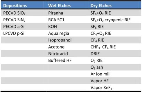
varies by eight orders of magnitude. ... 49 Figure 3-1: Unprocessed nanotubes, (a) produced by CVD and inspected by SEM, and (b) produced by
arc-discharge and inspected by TEM. ... 57 Figure 3-2: MEMS deposition processes with CNTs. Unprocessed CVD CNTs are shown in (a). CVD CNT
forests coated with PECVD SiO2 (b) and (d) and PECVD SiNx (c) and (e) show uniform, conformal coatings. The nanotube is visible in the center of the structure in (e). ... 59 Figure 3-3: A 12-wall arc-discharge CNT before any processing is shown in (a). The same tube after a
thin SiNx layer has been deposited is shown in (b). The walls remain intact, although somewhat obscured by the amorphous SiNx coating. Similar results were found for PECVD SiO2 (c) and LPCVD polysilicon (d). To summarize, all deposition processes tested appear not to damage the underlying CNTs. ... 60 Figure 3-4: Amorphous silicon deposited on CNTs by PECVD. (a) Unprocessed arc-discharge CNTs
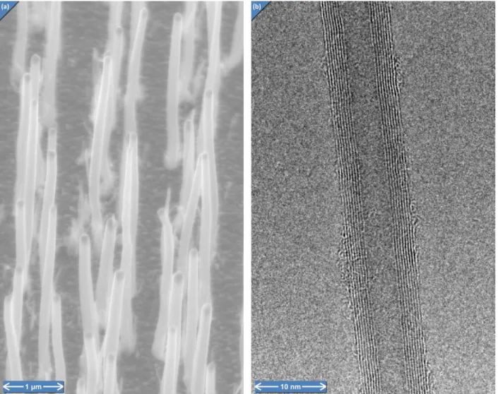
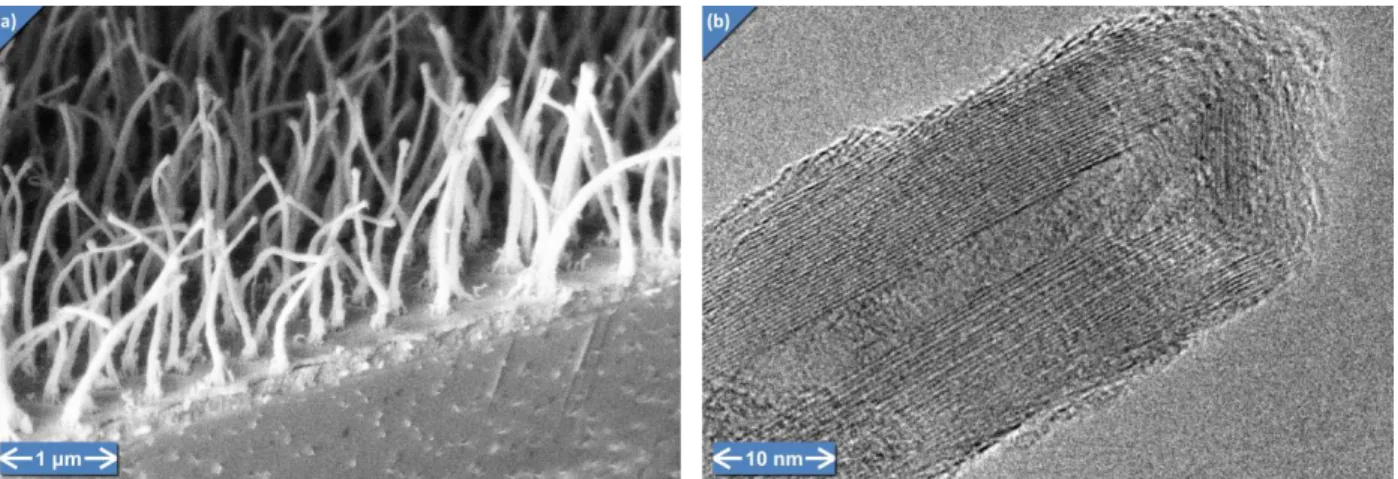
showing some defects and amorphous carbon material. (b) The same tubes, with amorphous silicon coating. Only slight defects are introduced to the tube structure. ... 61 Figure 3-5: These SEMs show CVD nanotube forests subjected to wet etches. (a) Unprocessed CNTs. (b)
Piranha does not cause noticeable damage to the CNTs. (c) KOH did attack outer layers of the CVD CNTs, thinning the CNTs over the 30-minute process. (d) Aqua regia attacked and removed the catalyst particles (dark spots at the CNT tips). (e) Acetone did no damage even after overnight exposures. (f) Nitric acid also attacked the catalyst. ... 62 Figure 3-6: KOH caused some damage to the outer walls of the MWNTs, introducing defects and
rendering the carbon more amorphous (less crystalline). The tube is shown before etching (a), with straight, ordered walls, and after etching (b), where some outer walls are no longer crystalline. ... 64 Figure 3-7: Xenon difluoride did not cause any significant damage to the CNT walls, although in this case
the less-stable end cap was slightly attacked after 30 minutes of etching. The tube shows good crystallinity after the etch (b) compared with before the etch (a). ... 67 Figure 3-8: These SEMs show that ion etch process inflict substantial damage on the tubes, for the
following chemistries: Argon (a), SF6 (b), SF6/O2 (c), CF4/O2 (d), CHF3/CF4 (e), and CF4 (f). Common damage modes include tip sharpening due to the field concentration in the tip region (all), and bending due to tube weakening and defect introduction (b,c,e,f). ... 68 Figure 3-9: Unprocessed CNTs are shown in (a). Little or no damage was observed for SF6/O2 cryogenic
etching (b), and Bosch Process DRIE (c). Common damage modes include tip sharpening due to the field concentration in the tip region (b—g), and bending due to tube weakening and defect
introduction (c,d,f,g). ... 69 Figure 3-10: Oxygen ashing causes substantial damage to poor quality CVD nanotubes (a) and only some
12
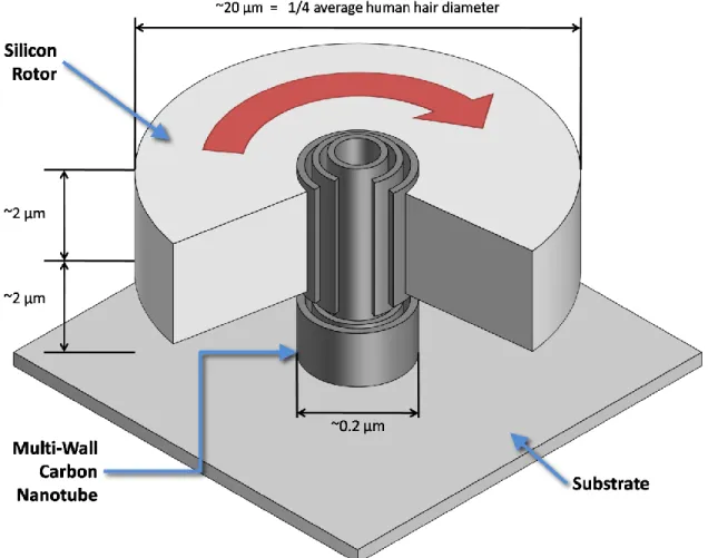
Figure 4-1: A schematic representation of the CNT bearing prototype, with a cut-away showing the structure of the CNT in the center. ... 75 Figure 4-2: The overall fabrication process. ... 78 Figure 4-3: Complete fabrication of a single device: CNT growth (a,b), SiO2 deposition (c), Polysilicon and Cr layer deposition ... 79 Figure 4-4: CNT growth on silicon substrates. (a) A dark-field optical microscope image shows the nickel
catalyst before CNT growth. At this magnification, only the alignment cross and labels are visible; the nickel dots intended to generate CNTs are too small to see. (b) An SEM shows that after CNT growth, the catalyst appears to have diffused around the substrate, leading to extraneous CNTs growing in unintended areas. ... 81 Figure 4-5: Chromium layers used in some CNT growth runs experienced significant peeling. Two device
areas are shown in the optical micrograph (c), and a closer view of a single device is shown in SEM (a), along with the central isolated CNT in (b). ... 82 Figure 4-6: Lack of repeatability is shown in three CNT growth runs. Run (a) shows a near ideal result,
with a single vertical tube in the center of the field (b). Runs (c) and (d) show increasing amounts of unwanted CNTs. ... 83 Figure 4-7: This image shows the 25 central isolated CNTs from a single sample containing a 5x5 array of
devices. After switching to the BC e-beam tool for catalyst patterning, repeatability improved substantially, although some diffusion of the catalyst (manifesting here as extra tubes or stumps) as well as non-uniformity of tube geometry is still present. ... 85 Figure 4-8: TEM images showing the poor crystalline quality of the CVD CNTs. A high magnification
image (a) shows that there is almost no graphitization in the tube, while (b) and (c) show much larger scale defects present in many tubes. ... 86 Figure 4-9: TEM Images taken by the Boston College team show the results of current annealing. A CNT
is contacted by a probe (a) and current passed through out. The amorphous structure before annealing (b) is transformed in to a much more graphitized structure (c), but the graphitic planes are poorly aligned and not straight. ... 87 Figure 4-10: Loose arc-discharge CNTs, shown in (a) and (b), contain many impurities, and tend to clump
together under the influence of van der Waals forces. CVD-CNT forests, like those produced by BC (c) and NanoLab (d) are easier to manipulate, although they do not have the necessary crystalline quality. ... 88 Figure 4-11: Fetching or "picking" a CNT from a forest of tubes from NanoLab. (a) The tube is contacted
with the manipulation probe, whose tip is coated in glue (dark region). (b) The bottom of the tube is cut using ion milling, leaving a cavity where the substrate behind the tube was milled (small dark rectangle). The tube is lifted with the manipulator tip. ... 89 Figure 4-12: Three types of holes were etched in the target prior to tube placement. The large holes in
(a) are for alignment of later process steps. These were etched in the silicon using the same etch as that used to define the rotor, described in 4.2.5. The small hole in (a) and (b) was made using the FIB milling function, to clear the native oxide. This hole is difficult to insert a CNT into, but provides for a strong attachment. (c) shows a shallower, wider basin, with a CNT already attached to it. The square at the base of the CNT is the deposited carbon. ... 90
13
Figure 4-13: The final stages of manipulating a CNT into place. After the base is attached with carbon deposition (a), the top of the tube is cut from the manipulator by FIB milling. The lone CNT is shown among its alignment marks in (c). ... 91 Figure 4-14: When viewed from the side, the CNT in figure 4-13 turned out to be heavily curved. While
this type of tube will not lead to a functional device, it is useful for practicing the fabrication
process. ... 92 Figure 4-15: PECVD SiO2 was applied to provide a space between the substrate and the rotor layer .The
oxide also conformally coated the CNT, shown in the center of (a) and enlarged in (b). ... 94 Figure 4-16: The conformal oxide layer caused problems when releasing the rotors. As shown in (a), if
the rotor was not properly aligned, the oxide could be cleared from the CNT-rotor interface before it is complete cleared from the rotor-substrate interface; although the CNT has been completely released from the rotor and the substrate (it is missing altogether) a pillar of SiO2 remains under the rotor. After further etching (b), the pillar is removed, and it is clear from the bottom of the rotor that the SiO2 “hump” surrounding the CNT is gone, leaving a pit in the rotor underside. ... 94 Figure 4-17: Turning the non-conformality of the resist coating process to advantage, the SiO2 encasing
the top of the CNT can be removed with HF whilst protecting the underlying release layer with photoresist. The process is shown schematically in (a), with SEMs from before (b) and after (c). .. 95 Figure 4-18: This released rotor was constructed from the curved, manipulated CNT pictured in figure
4-14. The rotor was still attached to the substrate (a and b) by the CNT and a pillar of polysilicon (which resulted from the topology caused by the horizontal portion of the bent CNT). The CNT is visible under the rotor, showing that the improved rotor-to-CNT bond was successful. When removed from the substrate and flipped over (using manipulators), the CNT is very clear (c and d). ... 96 Figure 4-19: Cryogenic (a,c,f) and DRIE (b,d,e,g,h) silicon etches are shown. The cryogenic recipe
produces good anisotropic etch profiles (a), but only when used with a metal mask; Otherwise, the resist cannot withstand the etch (c) and the rotor vanes are mostly etched away (f). The DRIE recipe can also produce good results, with only a resist mask (b). However, because the etch depth is so shallow, a non-aggressive recipe is used, which is highly sensitive to chamber temperature. Small, uncontrolled temperature fluctuations can lead to the formation of “grass,” or unwanted residual silicon pillars, illustrated in (d) and (g). The characteristic scalloping markings on the sidewalls, due to the alternating nature of the DRIE process, are visible in the close-ups (e) and (h). ... 97 Figure 4-20: The resist did not coat the top of the CNT pillar at the rotor center. This allowed the
polysilicon to be removed during the rotor etch, exposing the CNT shaft and the SiO2 surrounding it. This defect is shown optically (a), by AFM profile (b) and by SEM (c). Another device is shown before (d) and after (e) partial release. ... 98 Figure 4-21: An optical microscope was used to expose the thick resist. At 150x magnification, the
aperture (b) can be reduced such that the light covers an octagon of approximately 15 micrometer diameter, sufficient for protecting the center portion of the rotor (a). ... 99 Figure 4-22: BOE is used to remove the sacrificial oxide layer from underneath the rotor, as illustrated by
infrared transmission microscopy. The oxide is the light colored circle in the center of the rotors. On the left (a-d), rotors with CNTs (the small dark circle in the center) are shown, while the rotors on the right (e-h) have no CNTs, and vary in size to assist in monitoring etch progression. These
14
images were taken after 45 minutes (a,e), 60 minutes (b,f), 75 minutes (c,g), and 90 minutes (d,h) of etching. ... 100 Figure 4-23: These rotors are almost completely released, supported by a thin oxide pillar underneath
the rotor. ... 101 Figure 4-24: A schematic diagram showing the testing apparatus, consisting of micro-pipettes directed at the vanes of the rotor by a microelectronic probe station, and supplied with air by a syringe pump. ... 103 Figure 4-25: A still image captured from a test in progress, showing the rotor, alignment marks, and glass
micropipettes. No tests have succeeded in spinning a rotor, due primarily to the low quality of available CNTs. ... 104 Figure 5-1: Friction reported by the four selected literature studies (the selection criteria were dynamic
simulations that studied the rotational case) is plotted versus sliding speed. Selecting the most relevant papers has reduced the variation between reports to 2-3 orders of magnitude. ... 108 Figure 5-2: The initial (top) and final (bottom) configurations of CNTs used in validating the simulation.
These CNT cross-sections are superimposed on each other; in each simulation, a single tube was simulated independently, without interactions with any other CNT. The (5,5), (10,10), (15,15), and (20,20) CNTs migrated to the cylindrical stable configuration, while the (25,25) and (30,30) CNTs remained stable in the collapsed configuration. ... 112 Figure 5-3: Map of energy landscape for a (5,5)/(10,10) DWNT, as a function of translational and
rotational displacements. ... 113 Figure 5-4: Boundary condition regions in the baseline geometry (a 60 nm (9,9) CNT centered in a 50 nm
(14,14) CNT). ... 115 Figure 5-5: Example data collected from an isothermal constant velocity simulation at 200 GHz, showing
angular velocity (a), temperature (c), and kinetic energy (b) of each tube, along with other energies (b) and the running total of energy extracted via the thermostat (d). The dashed vertical lines represent the end of the startup transient and the beginning of the region used for fitting. ... 116 Figure 5-6: Radius data is shown over the course of an example simulation; the true radius differs slightly from the prediction... 117 Figure 5-7: Example data collected from an adiabatic constant velocity simulation at 100 GHz, showing
angular velocity (a), temperature (c), and kinetic energy (b) of each tube, along with other energies (b) and the total energy in the system (d). The dashed vertical lines represent the end of the startup transient and the beginning of the region used for fitting. ... 118 Figure 5-8: Angular velocity evolution (a) during an example coast down simulation at 250 GHz. The
small initial transient motion is due to the release of the constraints on the end atoms used during thermal equilibration. The rate of change of the angular momentum (d) can be approximated as linear for this short time simulation, or it can be fit with an exponential for longer times; these are shown as dashed and dotted lines, respectively. Temperature (c) and energy (b) are also recorded during the simulation. ... 121 Figure 5-9 - Angular velocity (a), energy (b), temperature (c), and angular momentum (d) evolution
during a spin-up simulation at 75 GHz. The inner tube’s angular velocity and angular momentum are held constant, while the outer tube gradually catches up. ... 123
15
Figure 5-10: Example phonon dispersion relation at zero temperature, for a (10,10) CNT, computed by GULP. ... 125 Figure 5-11: Example phonon density of states at zero temperature, for a (10,10) CNT, computed by
GULP. ... 126 Figure 5-12: Example phonon power spectra for a (9,9) CNT within a (14,14) CNT. The top row shows
the power spectrum for each tube including the interactions with the other tube, while the bottom row shows the spectrum for that tube in isolation. Each spectrum was measured 6 times, and the results are overlaid in different colors... 127 Figure 5-13: Difference spectra, showing the subtraction of the isolated tube spectra from their
respective interacting spectra. Each colored line corresponds to a different integration window in the simulation, all of length 1 ns. ... 128 Figure 5-14: Baseline (steady isothermal) simulations compared with selected results from the literature;
the baseline simulation agrees well with Servantie and Gaspard [24], which is the most recent rotational friction study. ... 129 Figure 5-15: Results from all the independent simulation strategies are superimposed on the results
from the literature. In the legend, “Coast-Down” (section 5.2.6.1), “Spin-Up” (section 5.2.6.2), “Steady Adiabatic” (section 5.2.5.2), and “Steady Isothermal” (section 5.2.5.1) refer to simulation type. The unsteady simulations included here employ the exponential fitting technique. ... 130 Figure 5-16: The same results are shown as figure 4-15, with a linear scale, and with some literature
results removed, to better show the level of agreement between simulation types. Note that while the spin-up and steady adiabatic results appear higher at higher speeds, this can be explained by the temperature accumulation inherent in these simulations, as explained in section 5.2.5.2. The coast-down simulation experiences less temperature rise (since energy is conserved, see section 5.2.6.1), and the isothermal simulation experiences no temperature rise (since a thermostat
actively regulates temperature). ... 131 Figure 5-17: When non-dimensionalized by the thermal kinetic energy the dependence of friction on
sliding speed is in excellent agreement across a range of simulation styles, particularly for low speeds. The grey line is a least squares linear fit of the isothermal steady simulations. ... 133 Figure 5-18: The linear and exponential fitting techniques for the coast-down (a) and spin-up (b)
simulations are compared. For the coast down, only angular momentum can be fit; the results agree well for the inner and outer tube. For the spin-up, the total energy method can also be used, and agrees with the linear angular momentum fit. In both cases, the linear method underpredicts the friction, for reasons described in section 5.2.6.1. ... 135 Figure 5-20: The dependence of the phonon spectrum on sliding speed is examined for the adiabatic
constant velocity simulation. The labels indicate the rotational speed for which that spectrum was computed, and each colored line represents a different integration window, each of length 1 ns. Units have been omitted from the y-axis because the units are arbitrary (the spectra were normalized to unit area) and spectra have been shifted vertically for ease of comparison. The frequency ranges that are most active during rotation are visible as plateaus of elevated intensity, at about 10-14 THz and 20-25 THz (the intensity between about 25-40 THz is nearly zero.) ... 136 Figure 5-21: The spectra of the rotating CNTs, with the spectrum of a still tube subtracted off to highlight
the differences. The labels correspond to the rotational speed at which the spectra were
16
ns (lines) or 0.1 ns (x’s). The agreement between different lines as well as x’s and lines indicates that the integration parameters are of adequate resolution. Two regions in which there is a lot of phonon activity (9-13 THz and 17-25 THz) are visible, especially in the inner tube. ... 137 Figure 5-22: Changing the averaging scheme does not affect the friction measurement. Shown is the
baseline adiabatic steady simulation, which averages 50 timesteps, and additional adiabatic steady runs averaging 500 timesteps. ... 139 Figure 5-23: Comparison of various thermostating techniques with the baseline (unthermostated,
adiabatic) simulations. The Langevin thermostat consistently over-estimates the friction, while the Berendsen and Nosé-Hoover thermostats agree well. ... 140 Figure 5-24: Dependence of friction on simulation temperature. These steady isothermal simulations
use a Nosé-Hoover thermostat to regulate the temperature ... 142 Figure 5-25: Non-dimensionalization of the friction by the thermal energy captures the linear
dependence of friction on temperature, allowing simulations at different temperatures to be collapsed onto a single resulting trend... 143 Figure 5-26: Tubes of two different lengths are shown. The Baseline tubes are approximately 1.7×10⁻⁴
times the persistence length, and the longer tubes are and 7.1×10⁻⁴ times the persistence length. ... 144 Figure 5-27: Effect of different CNT chiralities is investigated, using steady adiabatic simulations. Each
chirality has an associated interface radius (characteristic of the overall tube size) and spacing (between the two tubes) which are listed in table 5-5. Chirality does not have a strong effect at lower speeds, and the data agree well for different CNTs. However, at higher speeds, the tube with tighter spacing tends to experience increased friction, likely due to the increased strength of the interaction between tubes when the spacing is reduced. ... 146 Figure 5-28 Geometry for the graphene simulations consisted of two rectangular graphene sheets with a periodic boundary condition in both in-plane directions. ... 149 Figure 5-29: Friction in the graphene system, as a function of relative sliding speed. The baseline CNT
simulations are also shown for comparison. The larger error bars are likely due to the small size of the simulated graphene system, which does not provide for as many atoms across which to
17
L
IST OF
T
ABLES
Table 2-1: Reported and computed values for the atomic density in CNTs, showing differences between
sources. ... 51
Table 3-1: MEMS processes tested for compatibility with CNTs ... 55
Table 3-2: MEMS wet processes - parameters used ... 63
Table 3-3: MEMS dry processes - parameters used ... 66
Table 3-4: Carbon nanotube compatibility with MEMS processes ... 72
Table 4-1: Process parameters for prototype fabrication process ... 80
Table 5-1: CNT geometries used to validate simulation by testing for stable collapsed configurations.. 111
Table 5-2: Comparison of simulation types ... 115
Table 5-3: Reduced frequency for evaluating quasi-steady assumption in adiabatic simulations ... 119
Table 5-4: Parameters investigated for their effects on CNT friction ... 138
18
19
N
OMENCLATURE
Symbol Meaning
Unit cell length
- Carbon-carbon bond length
Fitting constants
Diameter of a carbon nanotube Energy in the system
Thermal energy
Total energy transferred via thermostat Non-dimensional friction force per atom Friction force
Force on atom
Lennard-Jones force
Force due to interaction with fictitious “solvent” particles
Number of degrees of freedom
Inter-wall spacing between carbon nanotubes
Second moment of area of the carbon nanotube
Moment of inertia of the carbon nanotube Moment of inertia of inner nanotube Moment of inertia of outer nanotube Wave number
Boltzmann constant
Length of a carbon nanotube Persistence length
Angular momentum of a carbon nanotube Initial angular momentum of the system Angular momentum of inner nanotube Angular momentum of outer nanotube Chiral index
Mass of one carbon atom Mass of atom
Chiral index Number of atoms
Number of atoms in inner nanotube Number of atoms in outer nanotube Energy transfer or accumulation rate
20
Nosé-Hoover parameter
Heat transfer rate (via thermostat)
Symbol Meaning
Radius of a carbon nanotube Radius of inner nanotube Radius of outer nanotube
Interface radius between two carbon nanotubes Position of atom
Nosé-Hoover reservoir Time
Timescale of steady behavior
Timescale of unsteady behavior
Simulation timestep Temperature
Desired temperature
Potential energy in the system, from an empirical potential function Velocity
Non-dimensional sliding velocity
Lennard-Jones velocity
Average thermal velocity of the atoms Young’s Modulus
Thermostat timescale parameter Reduced Frequency
Lennard-Jones energy parameter
Angle of rotation of the carbon nanotube Scale parameter for Berendsen thermostat
Kinetic friction coefficient
Surface atomic density (atoms per area) Interface atomic density
Lennard-Jones distance parameter Friction torque
Angular speed of a carbon nanotube Initial angular speed
Angular speed of inner nanotube Angular speed of outer nanotube
21
A
CRONYMS
Acronym Meaning
a-Si Amorphous Silicon
AFM Atomic Force Microscopy, Microscope, Micrograph AIREBO Adaptive Intermolecular Reactive Empirical Bond Order ASTM American Society for Testing and Materials
CNT Carbon Nanotube BC Boston College BOE Buffered Oxide Etch CVD Chemical Vapor Deposition DC Direct Current
DI De-Ionized
DRIE Deep Reactive Ion Etching DWNT Double-Wall Nanotube e-beam Electron Beam
EDX Energy Dispersive X-ray Spectroscopy FIB Focused Ion Beam
FTIR Fourier Transform Infrared Spectroscopy GULP General Utility Lattice Program
ICP Inductively Coupled Plasma JEOL Japan Electron Optics Laboratory
LAMMPS Large-scale Atomic/Molecular Massively Parallel Simulator LPCVD Low-Pressure Chemical Vapor Deposition
MD Molecular Dynamics
MEMS Micro-Electro-Mechanical Systems MIT Massachusetts Institute of Technology MWNT Multi-Wall Nanotube
NEMS Nano-Electro-Mechanical Systems p-Si Polycrystalline Silicon
PECVD Plasma-Enhanced Chemical Vapor Deposition PEEK Polyetheretherketone
PMMA Polymethyl Methacrylate RCA Radio Corporation of America RIE Reactive Ion Etching
SC1 Standard Clean 1
SEBL Scanning Electron Beam lithography
22
Acronym Meaning
STS Surface Technology Systems SWNT Single-Wall Nanotube
23
1 O
VERVIEW
The purpose of this thesis is to advance the state of knowledge about Carbon Nanotube (CNT) based rotary bearings for Micro-Electro-Mechanical Systems (MEMS) and Nano-Electro-Mechanical Systems (NEMS). The CNT bearing, which had been demonstrated in simple devices [1, 2] and which was further developed in part during the precursor to this thesis [3], relies on the structure of the CNT to enable rotation with low friction and minimal wear, or potentially even “anti-wear” or “self-healing.” Multiwall carbon nanotubes (MWNTs) are characterized by strong shells, comprising cylindrical tubes of covalently bonded carbon one atom thick. These shells nest inside each other, analogously to the manner in which graphene sheets stack to form graphite. While the strong shells provide a mechanically robust
framework to leverage in building devices, the lack of covalent bonding between shells enable adjacent shells to slide relative to each other with extremely low resistance. The CNT system is therefore attractive as a bearing.
1.1 Motivation
MEMS and NEMS have proven effective at providing functionality similar to their larger-scale counterparts, with significant savings in cost, weight, size, and power consumption. Examples of commercially successful devices include pressure sensors, accelerometers, inkjet printer heads, and mirror arrays. However, a significant limitation restricts the diversity of successful devices, which is well described by the taxonomy of Romig et al. [4]. Almost all current commercially successful devices are Class I (no moving parts) or Class II (moving but not contacting parts). The only exception is the micro-mirror array, which falls into Class III (contacting but not rubbing parts). A wealth of possibilities exists for Class IV (rubbing parts) MEMS, but despite plentiful laboratory demonstrations and prototypes, none of these possibilities have been realized in a commercially successful device.
The tribological phenomena of interfacial friction and wear are recognized [4, 5] as a leading cause of failure in Class IV MEMS, and are largely responsible for the absence of any commercially successful devices requiring such sliding motion. To improve the reliability of Class IV MEMS, it will be necessary to reduce friction at these interfaces, and especially to control the mechanisms that cause friction to increase over the device lifetime, by developing bearing technologies that counteract or mitigate these issues.
Recognizing the critical importance of bearing development for the future of MEMS, many have invested substantially in bearing research (see section 2.1). From simple bushings, consisting of parts rubbing directly on each other, to macro-inspired designs such as ball-bearings, to more complex systems such as gas or liquid film bearings, a diverse array of approaches has arisen. While most of these solutions offer greatly improved performance over bearing-less designs, often it comes at the cost of fabrication complexity or design restrictions, and further performance improvements are sometimes desirable. The landscape of micro bearing research is still ripe for novel concepts that offer strong performance with relatively straightforward implementation.
One promising approach would be the incorporation of CNT-based bearings. CNTs have long been known to exhibit low sliding resistance between adjacent walls [6], and several experimental
demonstrations have been accomplished [1, 2, 7-11]. Other experimental work has shown that friction performance can remain constant over 104 cycles, and even decrease after “self-repair” of the CNT
24
undergoing motion [12]. These encouraging properties can be attributed to the energetically favorable and chemically stable structure of CNTs, and the inability of debris to accumulate in the 0.34 nm gap between adjacent walls. Because of these properties, CNTs, and graphene, their planar analogue, are attractive as elements for constructing high reliability rotary and translational bearings, and thus reliable Class IV MEMS devices.
However, despite existing demonstrations and some attempts to measure friction in CNT devices, a clear understanding not only of the quantitative value of friction, but of the mechanisms that govern this friction, remains elusive. Because this question has yet to be resolved, and because of the relatively simple molecular structure of CNTs, simulation of CNTs for the purpose of measuring the friction has become popular [10, 13-27]. However, the tremendous interest has so far done little to resolve the question; in fact, considering all the friction estimates reported throughout the literature, the spread amongst these estimates is as much as eight orders of magnitude. More details on the discrepancies among the existing literature are provided in section 2.2.2.3 and section 5.1. It is of vital importance to the utility of these simulations that they be credible, which cannot occur until the variations in results between them have been explained. A large portion of this work (chapter 5) has therefore been devoted to a thorough investigation of all of the simulation methods employed to date, with the goal of identifying the causes of and resolving the discrepancies.
In order to truly advance the reliability of Class IV MEMS, it is also vital to understand those processes that lead to failure over time. Therefore, measurement of the time-history of friction performance in CNT and graphene bearings will be necessary to enable real world devices that take advantage of the bearing technology. Furthermore, an accurate picture of the wear processes, obtained by morphological examination of operating bearings, will contribute to this understanding. The
development of a manufacturable, robust test article, such as the CNT bearing prototype of this work, will enable measurement of the friction performance and wear characteristics of these bearings over time. The resulting bearing prototypes and accompanying qualitative and quantitative understanding will be critically important to future MEMS device designers, by providing a method for reducing device failures due to friction and wear in a predictable way.
1.2 Challenges
CNT bearings are a difficult problem, and there have been many challenges with which to contend. Some challenges are still outstanding, and more research work will need to be done to bring the concept of a CNT bearing to the state where it can be leveraged by applications.
One of the biggest challenges has been knowing how to fabricate MEMS devices which incorporate CNTs. The patchwork of data that exists in the literature is not readily accessible in the way that data on most established MEMS materials is. The work performed as a part of this thesis partially mitigates that issue, by providing a consistent reference on whether CNTs will have significant issues with any given process. However, much work remains to determine the precise variations in properties that these processes can cause, before CNTs can be considered a “standard” MEMS material.
In fabricating the prototype device, the largest challenge continues to be achieving an isolated, vertically aligned CNT with sufficient crystalline quality. Section 4.2.1 explains the details of why this is so difficult. Of the two options, each has different limitations. CVD grown tubes can be grown in the desired location with good control on orientation, but this becomes more difficult when single, isolated CNTs are required as opposed to CNT “forests.” A trade-off between control of location and tube crystalline quality exists, and a suitable optimum has yet to be found. For manipulation of CNTs into
25
place, arbitrary tube quality can be obtained, since tubes can come from any source, including arc-discharge synthesis. However, the process is extraordinarily tedious and time consuming, and control over tube orientation is limited by the available degrees of freedom and viewing angles in the
manipulation system. With more work, an effective protocol for consistently manipulating tubes into place may be developed, but the process will still require manual action for each CNT. At present, the lack of availability of isolated, vertically-oriented CNTs of sufficient quality is the reason that the prototype device described here has not successfully rotated.
Challenges also remain in understanding the friction in the CNT system. Surveying the existing literature on simulation of CNTs via Molecular Dynamics (MD) demonstrates that wildly different predictions of friction are possible, and without carefully considering the validity of the simulation and its relation to reality, the numbers cannot be taken at face value. When coupled with the paucity of experimental friction measurements, it becomes clear that extensive work remains to be done in validating these simulations. While the work here in unifying the disparate methods is a good start, experimental data is the only real way to ensure that the simulations are accurate. The prototype, when completed with a sufficiently high quality CNT, can provide this desperately needed data.
The simulations can also be extended to more closely describe the CNTs used in the experiments. One outstanding issue is scale: while real tubes used thus far comprise millions to billions of atoms, simulations are difficult with more than a few or tens of thousands. Increasing computational resources will mitigate this issue in time. There is also a schism between the characteristic timescales of the experiment and the simulations. The speed of available processors forces rotation rates in excess of GHz for the simulations; furthermore lower rates have higher noise relative to the thermal motion, so even longer running times or multiple parallel simulations are required to get an accurate result. Experimental data thus far collected has been constrained to mere Hz, and the model predicts that prototype device described here cannot exceed a few tens of MHz. Advanced time-lengthening
techniques for MD, such as temperature accelerated dynamics, might be able to bridge the inaccessible region in the future.
Finally, a major difference between simulated and real tubes is defects. As illustrated in section 4.2.1.1, real CNTs can have extremely high defect densities, and at times can seem to be more defect than proper tube. Simulations including defects have yet to be reported, partly because the description of defective geometry is much more complex than ideal CNTs. An initial way to include defects might be to introduce point defects such as vacancies or interstitials, randomly distributed throughout the
structure. Further work could implement procedures to design tubes with larger-scale defects. As real CNT quality improves, this gap will hopefully close from both ends in the future.
1.3 Goals of the Project
One major goal of the project is to demonstrate a prototype CNT bearing device that can be useful for applications. While the possibility of utilizing a CNT as a bearing has already been shown, in a few bold demonstrations [1, 2] (discussed in more detail in section 2.2.1), to be feasible, further work is necessary to incorporate them into useful devices. One possible extension of those technologies would be to transition from a horizontally oriented CNT to a vertically oriented CNT. The benefits of this orientation change are discussed in section 1.4. Additionally, it is hoped that a more manufacturable process for constructing CNT based rotors can be developed, which can eliminate some of the time consuming manual process steps employed in demonstrations to date. Construction of the prototype device will demonstrate that such improvements on the existing state of the art are feasible, and will also provide a baseline fabrication process that will be critical to the development of application devices.
26
Further, testing of the prototype will eventually provide some of the first ever experimental data on the behavior of the CNT bearing system, and specifically on the friction in the bearing. Prototype
construction is detailed in chapter 4.
In the process of developing the prototype device, an additional goal was set to establish some guidelines for the incorporation of CNTs in to MEMS devices, using the standard toolbox of available MEMS processes and techniques. CNTs have begun to be incorporated into various micro-electronic [28-34], micro-mechanical [1, 2, 35, 36], and micro-fluidic [37-40] devices. Before using established MEMS fabrication procedures on CNTs, it is important to know what effects these procedures will have. Researchers have investigated the effects of the processes that make up their fabrication procedures, and hence, as a result of the development of fabrication processes for these devices, a patchwork of knowledge about the effects of various processes on the CNT is beginning to emerge. However, a comprehensive reference describing the compatibility of CNTs with a broad range of processes in a consistent manner (in the vein of Williams’ extensive etch rate tables [41, 42]), does not exist.
Therefore, the creation of such a reference has been undertaken, in order gain insight into the effects of our own processes of interest, and to provide a useful tool for future MEMS designers hoping to
incorporate CNTs. This work is detailed in chapter 3.
In addition to building an example CNT rotor, it also became clear that there is a great deal of work still needed to understand the physics of the CNT bearing system. Few of the experimental
demonstrations of CNT bearings have captured data on the friction, so the bulk of available data comes from simulations, typically employing molecular dynamics techniques. Unfortunately, the values for friction reported in this literature vary by as many as eight orders of magnitude, which make it difficult to use the data with confidence. Furthermore, a description of the mechanisms causing the friction, as well as knowledge of the dependence of friction on parameters of an individual CNT system, remains wanting. This work has therefore attempted to address these questions, by performing a suite of molecular dynamics simulations of diverse configurations and parameter sets, in a consistent and controlled manner. The goals are to establish the relative importance of and quantitative dependence on the system parameters, to identify the causes of the discrepancies in the literature, and to identify the underlying mechanisms causing the friction from a fundamental perspective. This work presents for the first time a comparison of the existing CNT bearing simulation literature, a consistently implemented array of simulations spanning the parameter space of that literature, and analysis of how the phonons (system natural modes) contribute to the interaction of MWNTs, providing new insight about the mechanisms driving friction. The simulation work is described in chapter 5.
1.3.1 Summary of Objectives
In summary, the scope of the thesis is bipartite: A prototype CNT bearing device is constructed, demonstrating a baseline fabrication process for CNT bearing devices, and simulations are conducted to study the friction in CNT bearings, focusing specifically on resolving the disagreement between reports in the literature on the quantitative value of friction, by spanning the parameter space and range of techniques employed in the by prior works with a consistently implemented suite of numerical experiments. The objectives of the work are to:
1. Construct a prototype CNT bearing device based on a vertically oriented isolated CNT a. Identify which MEMS fabrication processes are compatible with CNTs (chapter 3) b. Design a CNT bearing device for optimal performance (section 4.1)
27
c. Develop a fabrication process, address the issues arising during fabrication, and complete fabrication of the prototype device (section 4.2)
d. Develop a testing system to measure the prototype performance (section 4.4) 2. Simulate friction in CNT bearings
a. Review the existing literature on CNT bearing friction simulation (sections 5.1 and 2.2.2) b. Develop a simulation protocol to re-implement the techniques reported in the literature
using consistent parameters (section 5.2)
c. Demonstrate agreement between independent simulation techniques (section 5.3.1) d. Determine the dependence of friction on the system parameters (section 5.3.3) e. Identify the mechanisms that cause friction, by exploring the natural modes that make
up the system behavior (sections 5.3.2 and 5.2.7).
1.4 Impact
This thesis provides theoretical insight from the broad and consistent assessment of simulation techniques for estimating CNT friction, and practical fabrication development work on the prototype device (including testing of CNT compatibility with MEMS processes) for applications enabled by the proposed bearing technology.
1.4.1 Practice
The first major impact of this work is the development of a CNT bearing prototype fabrication process that builds on previous demonstrations. The new idea is to orient the CNT vertically, instead of horizontally. Figure 1-1 illustrates the general differences resulting from this orientation change. Because MEMS Fabrication relies so heavily on lithography for defining the geometry, fabrication capability is highly anisotropic; in the dimension normal to the substrate, only limited shapes can be constructed. By orienting the CNT in this dimension, both of the other two dimensions (which make up the plane of the rotor) become accessible to the geometry.
This seemingly simple change has wide-ranging implications. First, axisymmetry in the rotor and stator becomes possible. This is of immediate utility, because it allows improved control over the rotor balance, and hence, higher rotational speeds are attainable. Additionally, axisymmetry allows much finer control over the interfacing between the rotor and the stator. For example, electrodes for electrostatic actuation can be spaced arbitrarily around the circumference, in both the rotor and the stator. Additionally, the capacitive gap between rotor and stator can be tightly controlled, and consistent for all rotor angles. With this capability, rotors can be designed with high torque, uniform torque coverage, and bi-directional actuation capability, leveraging the extensive knowledge of electrostatic motors already developed [43]. Besides electrodes, other devices can also benefit from axisymmetric distribution around the rotor periphery, such as blades or vanes for interaction with fluids (e.g. turbines, compressors, or pumps), or optical redirection (e.g. mirrors or shutters).
28
Figure 1-1: The advantage of a vertically oriented CNT, namely, the capability to fabricate axisymmetric or other flexible rotor geometries, is shown.
The prototype fabrication process developed for this work is the first CNT based rotor to use such a configuration, demonstrating an axisymmetric rotor with vanes. In essence, the device is a micro- or nano-turbine. In addition to proving that the concept can be fabricated, the prototype also serves as a platform, which can be used as a starting point for designing other devices that make use of the bearing. Insights gained on what fabrication steps pose the most challenges, and how they can be resolved, will be useful for future work in CNT bearing application design.
There are additional contributions that arise from the use of a vertical CNT as well. First, the prototype provides a model for how CNT bearings might be constructed in a more manufacturable fashion; instead of painstakingly hand-selecting CNTs and patterning features by e-beam lithography around each one, CNTs can be grown in place, with the vertical orientation, by Chemical Vapor
Deposition (CVD). While current state-of-the-art CNT growth does not provide sufficient CNT quality to enable rotation, this will likely be a key enabler for wafer-scale mass-production of CNT bearing devices if that challenge can be resolved.
In the mean time, this work has also demonstrated manipulation and attachment of individual nanotubes to desired locations (see section 4.2.1.2). Vertical orientations have been obtained, with some error in the angle of alignment. This alternative strategy, while not cost-effectively
manufacturable in high volumes, provides another route for incorporating CNTs into MEMS devices. In cases where CVD growth is not possible, manipulation can be a useful way to test proof of concept devices before investing in other CNT placement strategies. For example, the development time for any device requiring vertically oriented or isolated CNTs, such as field emitters using carbon nanotube tips [44-46] or Atomic Force Microscope (AFM) tips using CNTs for high resolution [36, 47] might be shortened by having such a rapid capability to attach individual CNTs to the desired locations.
Another major impact, derived from the efforts to develop a fabrication process for the prototype, is the creation of a knowledge base describing the compatibility of CNTs with common MEMS processes.
29
Data have been available on CNT compatibility on a piecemeal basis, as researchers try a few processes in fabrication of a particular device; however, a single catalogue of CNT compatibility does not exist. A wide variety of processes have been applied to CNTs in a consistent manner, and the morphological changes at a bulk and atomic scale have been assessed, by Scanning Electron Microscopy (SEM) and Transmission Electron Microscopy (TEM), respectively, in each case. While it may be of interest to have other quantitative data concerning the effects of the processes (such as Raman spectra, conductivity measurements, etc.), breadth (i.e. number and diversity of processes documented) has been
emphasized over such depth. It is proposed that device designers interested in incorporating CNTs into their devices will want a quick check to see whether to even consider certain processes, and that having selected a process, they will characterize its effects in a manner that most closely evaluates the
performance characteristics of interest for their application. This contribution is therefore important as an initial reference resource.
The test device paves the way for a host of micromechanical devices. Any rotating mechanical device would be a candidate for miniaturization with MWNT bearings, but a few applications in particular stand to benefit significantly.
MEMS chemical and biological sensors have been in development for decades [48-53]. However, these systems typically rely on a pump to push analyte through them, or a vacuum pump to evacuate them. To date, the best MEMS vacuum pump constructed (to the author’s knowledge) can attain a pressure of 164 Torr [54] when backed by atmosphere; further vacuum performance might be possible with a rotary pump, such as those enabled by a suitable high-speed MEMS bearing. Other MEMS pumps have not proved capable of meeting the requirements of the sensors [50]. So far, in order to deploy these systems, bulky macro-scale pumping equipment has been needed. If a suitable MEMS pump could be developed, the entire system could be miniaturized to a convenient, portable size, while at the same time reducing power consumption. The MWNT bearing seems to be well suited to pumping applications, as its high stiffness can lead to high operating speeds. It is also capable of operating in a vacuum. Furthermore, it would not require an external electrical or compressed air supply, like some competing bearing technologies.
An additional application for which the MWNT bearing has promise is a microscale rotating gyroscope. Microscale gyroscopes exist based on the tuning fork design, but a true rotating disk could provide improved performance [55]. The ability of the bearing to provide very low “wobble” (angular displacement of the axis of rotation) could reduce the dominant cause of errors in dynamically tuned gyroscopes. The high stiffness could enable high-speed operation, leading to improved bandwidth and high sensitivity. In addition, the low friction suggests that the drive power to operate the gyroscope could be very low.
Another potential application is on-chip flywheel energy storage. The energy storage density capacity of a flywheel is limited primarily by the strength of the flywheel material. Any given flywheel can store energy per unit thickness scaling as the fourth power of the radius and the square of angular speed. However, to keep the stress below the material limit, the angular speed must vary inversely proportional to the radius. As a result, the energy storage per unit thickness scales with disk area, or in other words the energy storage density (energy per unit mass) is completely independent of the disk size. Scaling flywheels down to the microscale does not hurt performance, and in fact could improve it since micro-sized materials can be made with fewer flaws, and hence higher material strength. Energy stored in silicon flywheels has comparable energy density to batteries, but could potentially be
discharged much faster – in other words the power density of the flywheels could be high, providing short bursts of power on demand. The MWNT bearing could potentially make such flywheels feasible by
30
enabling high-speed rotation, and by providing a low-friction support that reduces unwanted energy dissipation over time.
The prototype device is a simple microturbine, extracting work from the airflow to overcome the friction. Further development of more advanced (and more useful) turbomachinery based on CNT bearings would be another interesting application. Turbomachines have been proposed [56, 57] for providing electrical power at a small scale, as an alternative to batteries. The fact that the power produced scales as the area (which controls the airflow rate) while device weight scales with the volume indicates that microturbomachinery could have a substantial advantage in power density. If successful, the MWNT bearing technology developed here might serve as a unique alternative to the gas bearings so far employed in microscale turbomachinery, by potentially allowing further size reduction and higher speed operation.
1.4.2 Theory
On the simulation side, the thesis has addressed the ongoing issue of large discrepancies between reported values for friction in the CNT. It has been shown that by carefully controlling all the
parameters of the simulation, friction numbers that agree well can be obtained even for several distinct types of simulation, and various methods of extracting the friction measurement from the simulation. By implementing these multiple, independent methods in a consistent manner, and obtaining good agreement among the results, confidence in the simulation’s ability to predict device performance is improved. This confidence is critical to acceptance of these simulations as a useful tool in evaluating design concepts.
Furthermore, the dependence of the friction value on the different parameters that are expected to influence it is determined, by ensuring control over all parameters and systematically varying one at a time. The parameters include properties of the system (e.g. geometry, temperature, rotation speed) as well as simulation control parameters (e.g. simulation initial and boundary conditions, thermostat type, averaging windows, and strategies for measuring the friction). This information is important for all CNT simulators, so that a consistent approach to modeling CNT friction can be used.
Finally, phonon power spectra have been computed for CNTs undergoing simulation. Phonons are the natural modes of the system, and the goal is to identify which modes are responsible for friction. It is demonstrated that there is not a particular phonon or few phonons that contribute especially strongly to the interactions between rotating tubes; instead, the interaction appears to be broadband. There are two bands which are particularly emphasized, between about 10-14 THz and 18-25 THz, but these become broader and less well defined for higher rotational speeds.
1.4.3 Summary of Contributions and Main Outcomes
In summary, this thesis has advanced the state of knowledge about CNT bearings by both
developing a prototype CNT bearing test device, and by examining CNT friction through simulation. The prototype, consisting of a rotor with vanes for air-driven actuation supported on a vertically aligned, isolated MWNT, proves the feasibility of constructing CNT bearing devices having such a configuration. Additionally, the fabrication process provides a guideline for how such devices can be constructed, based on a surface micromachining approach with a sacrificial release layer, polysilicon rotor layer, e-beam lithography and a combination of wet and dry etching. This fabrication process will be a useful starting point in designing fabrication plans for subsequent CNT bearing devices. The thesis also includes a consistent and broad assessment of the effects of MEMS processing techniques on CNTs, including those processes used for the prototype fabrication, as well as others of general interest to