An API for Location Aware Computing
by
Jason Murray Bell
Submitted to the Department of Electrical Engineering and Computer
Science
in Partial Fulfillment of the Requirements for the Degrees of
Bachelor of Science in Electrical Engineering and Computer Science
and
Master of Engineering in Electrical Engineering and Computer Science
at the
MASSACHUSETTS INSTITUTE OF TECHNOLOGY
January 2003
c
2003 Massachusetts Institute of Technology. All rights reserved.
Author . . . .
Department of Electrical Engineering and Computer Science
January 17, 2003
Certified by . . . .
Seth Teller
Thesis Supervisor
Accepted by . . . .
Arthur C. Smith
Chairman, Department Committee on Graduate Theses
An API for Location Aware Computing
by
Jason Murray Bell
Submitted to the Department of Electrical Engineering and Computer Science on January 17, 2003, in partial fulfillment of the
requirements for the Degrees of
Bachelor of Science in Electrical Engineering and Computer Science and
Master of Engineering in Electrical Engineering and Computer Science
Abstract
Indoor, location-aware devices have the potential to provide extremely useful resource and building information to human users; for example, a location-aware PDA could potentially provide map information in real time. We have developd a complete, extensible, indoor location-aware API to allow clients to interact with building and resource data stored on a central server. We have designed our own data model, emphasizing a space’s adjacency relationships to other spaces as the most important relational characteristic. Route finding is a fundamental algorithm for the exploration of such a data model; we investigated, implemented, and evaluated several such algo-rithms. Furthermore, we have implemented both a server and several clients, demon-strating the robustness and reliability of the API. The API’s most complex client, the CampusMap application, runs on a commodity graphics workstation and allows a user to interact with a full, three-dimensional model of campus. CampusMap gen-erates lowest-cost routes between any campus location by interacting with a Location Server, visualizing campus spaces, and instantly updating route results.
Thesis Supervisor: Seth Teller
Acknowledgments
I would like to thank my advisor, Seth Teller, for providing me inspiration, guidance, and support throughout the creation of this project.
Thanks also to Sean Markan, Allen Miu, Patrick Nichols, Max Van Kleek, and Hari Balakrishnan, whose input on the design was invaluable.
I dedicate this thesis to my family and Christine in appreciation of their love and support.
Contents
1 Introduction 8 1.1 Contributions . . . 9 1.2 Motivating Applications . . . 9 1.2.1 Real-time Mapping . . . 9 1.2.2 Software Flashlight . . . 10 1.2.3 Active Signage . . . 10 1.2.4 Stuff Database . . . 101.3 The Location Aware API - Design Overview . . . 11
1.3.1 A Client-Server Architecture . . . 11
1.3.2 Terminology and Data Structures . . . 12
1.3.3 Notational Conventions . . . 15
1.3.4 System Architecture . . . 15
1.3.5 Security and Privacy . . . 16
1.4 What the API Does Not Provide . . . 17
1.5 Related Systems . . . 17
1.5.1 GIS with Route Finding . . . 18
1.5.2 Drishti: Navigation for the Blind . . . 18
2 Location Aware API 20 2.1 Requirements . . . 20 2.2 Supporting Projects . . . 21 2.2.1 The BMG Project . . . 21 2.2.2 Cricket and GPS . . . 22 2.3 API Details . . . 23 2.3.1 A Network API . . . 23 2.4 Server Implementation . . . 24 2.4.1 Java Class . . . 25
2.4.2 Java Class - RMI Server . . . 26
2.4.3 Network Server . . . 27
2.5 Client Details . . . 29
2.5.1 Algorithms . . . 29
3 API Clients 47
3.1 RouteFinder . . . 47
3.2 CampusMap . . . 48
3.2.1 User Interface Details . . . 49
3.2.2 Using Dijkstra’s to hide latency . . . 50
3.3 Active Signs . . . 53
4 Future Work and Conclusion 55 4.1 Searching the dual of the Space-Portal graph . . . 55
4.2 Conclusion . . . 57
A Description of API functions and Project Build Instructions 59 A.1 Building the Project . . . 59
A.2 Running clients with the RMI Location Server . . . 60
A.2.1 Starting the RMI Server . . . 61
A.2.2 Starting RouteFinder . . . 62
A.2.3 Starting CampusMap . . . 62
A.3 Location Aware API documentation . . . 63
A.3.1 Package . . . 64
A.3.2 Interfaces . . . 65
A.3.3 Classes . . . 66
B LocationServer Network Protocol 80 B.1 Message format . . . 80 B.1.1 Function names . . . 80 B.2 Object Serialization . . . 81 B.2.1 Basic variables . . . 81 B.2.2 Space datatype . . . 81 B.2.3 Portal datatype . . . 82 B.2.4 Position datatype . . . 82 B.2.5 Location datatype . . . 82 B.2.6 Virtual Tag . . . 83 B.3 Future Improvements . . . 83
C The Location Aware API Standard Library 84 C.1 JavaDoc for Library Methods . . . 84
C.1.1 Package . . . 84
List of Figures
1-1 The Location Server presents an organized view of campus geometry data as Spaces and Portals (adjacencies). . . 12 1-2 System Architecture of the Location Aware API . . . 16 2-1 Over the network: a client request and a server response. The client
first sends the command “getSpaceFromLocation”, a delimiting char-acter, “|”, and the location information serialized with a standardized format (see B.2). The server then sends a response code “space”, a delimiting character, and the formatted Space name. . . 24 2-2 The getSpace request recast as a Java method signature. . . 24 2-3 Java, a functional language, providing a high-level layer between the
network protocol of the Location Server and the client . . . 25 2-4 A client requests a Space’s polygon . . . 28 2-5 A client incrementally explores the campus map depth-first. Each step
shows the discovery of additional Spaces. . . 30 2-6 A graph is explored breadth-first. Each node is labeled with its distance
from the root. (a) shows the graph with explored nodes and edges darkened. (b) shows the graph after a breadth-first iteration. . . 32 2-7 A graph is explored depth-first. (a) shows the graph with explored
nodes and edges darkened. (b) shows the graph after a depth-first iteration. Notice that the explored path tends to extend narrowly from the initial Space. . . 33 2-8 A simple polygon (outline, in bold) and its Delaunay triangulation
(internal triangles). Triangles are offset from polygon outline and other triangles for clarity . . . 34 2-9 An illegal path through a polygon - it exits the border and crosses into
forbidden areas. . . 35 2-10 A simple polygon, triangulated, with a short path from one border
location to another. . . 36 2-11 The RouteFinder GUI. Part (a) shows the paths with polygon
triangu-lation, part (b) without. Part (c) shows the same route with iterative filtering applied. . . 37 2-12 Our path-finding algorithm works quite well, correctly traversing the
2-13 Legal, but unnecessarily twisty Space paths (a) with and (b) with-out triangulation. (c) shows the path after iterative filtering, which removes the twist. . . 41 2-14 A path (a) is iteratively shortened, resulting in (b). Endpoints marked
with an ’X’ are eliminated, and their adjoining line segments condensed into a single segment. . . 42 2-15 The path from Figure 2-10 (a) is cubic spline interpolated (b) and
resampled at a constant segment length (c). Part (d) shows the new endpoints connected with line segments . . . 43 3-1 RouteFinder plots a route from one office to another on NE-43’s eighth
floor with no path filtering. . . 48 3-2 RouteFinder plots a the same route as in Figure 3-1 but with iterative
filtering. . . 49 3-3 RouteFinder plots the same route as in Figure 3-1, but shows the
triangulation in intermediate Spaces. . . 50 3-4 CampusMap uses the Java3D graphics system to display an interactive,
3-dimensional view of MIT’s Building 1. A route is plotted from one office to another with path filtering. . . 51 3-5 CampusMap displays a map of some floors in NE-43. A route goes
from an office on the second floor to an office on the fourth floor. . . . 52 3-6 An Active Sign displays directions to an upcoming meeting. Part (a)
shows one half of the sign allowing user input. Part (b) shows the other half of the sign displaying Location and route information. . . 54 4-1 The dual of a graph. (a) shows the original graph, (b) shows its dual 56 4-2 (a) shows a path from node 1 to node 5. (b) shows a shorter path that
goes through node 2 only once. . . 56 4-3 The shortest path from start to finish is via route (a). Our algorithms
will not allow the shaded space to be reentered, and give a shortest path of (b) . . . 57 A-1 The RouteFinder GUI. Users can view a map of a single floor, perform
route finding, and test the results of different path filtering algorithms. 60 A-2 The CampusMap GUI. Users can search a single floor, a building, or
Chapter 1
Introduction
Location Aware computing is a powerful new paradigm for building software and hardware systems. This thesis describes an Application Programming Interface (API) for indoor mobile computing services named the Location Aware API. It enables mobile applications to ask three basic questions about their environment:
1. What is the nature of the building geometry surrounding me? 2. How can I move from one area to another?
3. What are the locations of certain indoor objects?
Mobile computers are becoming more and more powerful; many such devices have built-in wireless networking hardware and fast, capable color graphics displays. Such devices are ideal platforms for location-aware clients since they have the power to process geometry data and to perform useful location-aware algorithms in real time; that is, interactively, as a user moves from place to place.
In this paper, we explain the development of our Location Aware API, which al-lows any networked software client to obtain access to the database of MIT’s building data. The Location Aware API remaps the database information into well-defined data structures with specific relationships, optimized for use by both mobile clients with modest hardware resources, as well as high-end graphics workstations.
This chapter first describes a list of contributions this thesis makes to the field of computer science and engineering. It then describes some motivating applications that influenced the development of the Location Aware API. Then, it gives a design overview of the entire system; each major component communicates with the others via the Location Aware API. The chapter concludes by describing what services are
not provided so that users can understand why some capabilities were intentionally limited.
1.1
Contributions
This thesis makes three main contributions
• A simple, powerful network API providing indoor geometry, adjacency, and virtual tag information. The API furnishes a low-level abstraction over our campus geometry database.
• A Location Server implementation which provides real campus building data to networked clients.
• Several Location Aware clients performing route finding and other high-level algorithms using only the Location Aware API to access indoor data.
1.2
Motivating Applications
The Location Aware API was inspired by the goal of providing a service for several location-aware motivating applications. The Location Aware API intends to support and aid in the development of these or similar applications.
1.2.1
Real-time Mapping
This API provides clients with the fundamental ability to perform route finding. A route is a sequence of spaces that a person can navigate sequentially. An application might wish to find the first valid path from one space to another, or it may want to find a route optimized for minimum cost or other criteria.
A real-time mapping application needs the capability to access the complete corpus of campus geometry data, as well as to determine which spaces are adjacent. It can use this data to plot a route from one location to another or simply to tell in which direction a certain resource is located.
Our API is designed with route finding algorithms in mind. The Standard Library (Section 2.5.2) provides several route finding and campus exploration algorithms that use the Location Aware API for low-level calls.
1.2.2
Software Flashlight
A standard flashlight uses an electrically powered light bulb to project light onto the world; a software flashlight uses a computer to project data onto the world (see [12] and [2] for current projects). A location aware computer with a portable data projec-tor would be able to act as a software flashlight; the projecprojec-tor would display useful images on a wall, ceiling, or floor, depending on its current location and orientation. The sofware flashlight has the important ability of directional awareness, which this API also supports.
This could be extremely useful to “peer into” walls without having to tear them open. Maintainance crews would be able to use a software flashlight to show the location of electrical conduit or plumbing, marking them for later inspection. Such “virtual” marks would be superior to traditional methods like permanent ink or spray paint because they would be automatically recorded to a persistent database. They would also not permanently mar surfaces or get “erased” by future improvements.
1.2.3
Active Signage
An active sign is an electronic display which is location-aware; this location-awareness can be permanently encoded, if the display has a fixed position, or driven by location-aware hardware, such as Cricket. With access to the Location Aware API and asso-ciated data, it could give timely, location sensitive information to nearby users.
Active signs are a perfect example of location aware computing; people interacting with the signs could receive real-time location information about meetings, events, or emergencies. An active sign knowing its location could give interactive maps to events or away from hazards. It could even serve as a sort of location aware “message board,” allowing users to leave notes for their friends, or directing special messages to sections of campus or parts of buildings.
1.2.4
Stuff Database
Indoor location sensing hardware is making it possible to track large numbers of objects by determining their proximity to fixed tag sensors or by recording when objects pass beneath sensors in frequently trafficked areas. The sensors can be very small, thin, and inexpensively produced; they could be easily attached to valuable personal possessions. This would allow an owner to locate very mobile or frequently borrowed items, such as books, telephones, or computer hardware, by querying a
database for the last known registered location of an item’s tag.
An interactive Stuff Database GUI would be a valuable tool for owners wishing to view the locations of their “stuff.” A scrollable, zoomable map could display the locations of stuff by querying the tag sensor database in real time. Community-owned objects, such as printers, water fountains, and workstations, might also be displayed on the map. Users could give permission for the system to allow the display of personal “stuff” information to other users; this would implicitly allow borrowing, since one’s personal belongings would show up on another person’s Stuff Database GUI. The tag sensing infrastructure would track borrowed items, so users could find out where their publicly available belongings were.
Our API supports clients who need both indoor geometry data and the ability to track location aware hardware tags. The virtual-tag class supports a named tag with a location updated via hardware infrastructure or by user input.
1.3
The Location Aware API - Design Overview
This section describes our Location Aware API, the data structures used by our API, and the way the data structures interact with each other. It also describes the high-level architecture of a Location Aware API implementation.
1.3.1
A Client-Server Architecture
Our API has a client-server architecture, in which clients communicate with a server over a network. Our subsequent discussion assumes that network connections are standard TCP/IP connections [7]. TCP/IP provides a persistent, end-to-end reliable, stream-based connection between two clients over a network. We define a protocol for the exchange of data over a TCP/IP connection in Appendix B; however, our network protocol maps very nicely to a functional language description, in which a client communicates with the server by calling methods on it (see Section 2.3.1). This is a very natural way to describe the Location Server functionality; most of our subsequent discussion will describe server requests as Java language method calls. However, it is important to remember that the API is both fully network enabled and language agnostic.
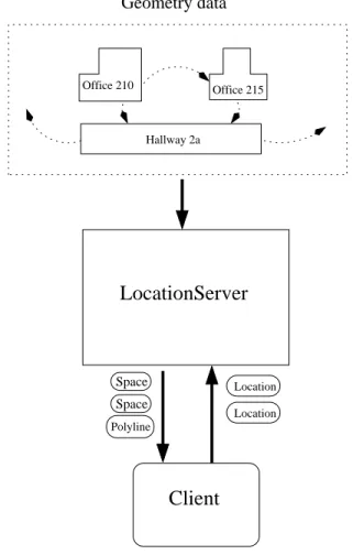
Office 210 Office 215 Hallway 2a Location Location Space Space Geometry data LocationServer Client Polyline
Figure 1-1: The Location Server presents an organized view of campus geometry data as Spaces and Portals (adjacencies).
1.3.2
Terminology and Data Structures
Our Location Aware API provides a simple, standardized interface between a build-ing geometry database and mobile computbuild-ing clients. This API defines a common structure for geometric data, including named spaces with closed geometric bound-aries, a mapping between (x, y, z) location information and space information, and adjacency information for connected spaces. It builds on the work of the BMG project ([8] and Section 2.2.1), which generates a large pool of relatively unstructured indoor geometry data from MIT’s AutoCad floorplans; we provide a convenient, structured abstraction over this massive quantity of data.
This document relies on the following terminology to describe the entities used by the Location Aware API.
2-dimensional and 3-2-dimensional data associated with them, as well as virtual tags marking the Positions of objects within a Space. The 2-dimensional data bounds the floor region of the Space and specifies areas where people cannot walk, such as pillars or internal walls. The 3-dimensional data consists of walls, ceilings, windows, and other objects associated with a Space.
Spaces also have an important type property. Current Space types include “STAIR,” “ELEVATOR, ” “ROOM, ” and “OUTDOOR.” Clients can use the Space Type as a filter when running search algorithms. For example, a wheelchair-bound individual may wish to disallow Spaces with Type “STAIR” when attempting to navigate from one place to another.
Spaces also contain references to zero or more Portals and Virtual Tags, which are described below.
Adjacency - Two Spaces are adjacent if a person can easily move between them without having to pass through any other Spaces. For example, an office with an open door is adjacent to its connecting hallway. Adjacency information is important for route finding applications or clients who need to find objects within nearby, connecting Spaces
Portal - This is an entity that captures the notion of Adjacency with important additional properties. A Portal is a directed adjacency: a person can only move through a Portal in one direction. This helps us to support vertical Portals, which have different costs associated with upward versus downward traversal. A Portal has a pointer to exactly two Spaces; the Spaces must be Adjacent to each other. A Portal also has a weight associated with the action of traversing it. This allows us to model the Spaces on campus as nodes in a standard graph connected by edges (Portals) with appropriate weights.
Optimal route finding algorithms can use this information to find the most desirable routes or to eliminate impossible ones. For example, a Portal with an infinite (or maximally high) weight might represent a locked door. An optimal route finding algorithm would automatically route around such an obstruction. Portals, like Spaces, also have a type. These types can specify whether a Portal is a vertical adjacency (connecting landings on stairwells), a normal door, or an effective Portal, indicating that two Spaces are adjacent but do not share a wall. Search algorithms can use Portal types to eliminate adjacencies that have undesirable characteristics. For example, a person might associate vertical
Portals with a higher cost, helping to minimize the number of time-consuming stairs and elevators encountered during travel.
Position - This is the location of an object in precise (x, y, z) coordinates. Our definition of Position includes specifications of a reference frame and units. A Position can also have a measure of uncertainty, and can specify a probability distribution for the (x, y, z) coordinates.
Location - A Location contains a Position; additionally, it specifies a heading vector, along with a heading probability distribution. The heading vector allows us to specify the direction of an object, which is important for direction aware clients, such as a software flashlight.
Location Server - This is a networked server that receives requests about the envi-ronment and responds with appropriate data. The Location Server is a key com-ponent of the Location Aware API architecture; all clients communicate with it via the Location Aware API. The Location Server has access to a database of raw geometry data, but presents clients with an organized view of the data. Figure 1-1 shows how a client is shielded from the unstructured, unorganized geometry data by the Location Server.
Virtual Tag - A virtual tag is an object that belongs to a single Space with two properties: a globally unique tag name and a Position. Location aware hardware tags, such as a tag based on the Cricket platform (Section 2.2.2), can use the Location Aware API to update the Position of the corresponding Virtual Tag. A client can discover which objects reside in a Space by querying the Location Server for its list of Virtual Tags. This enables a client to find a printer in a certain room, or where specific pieces of furniture are located. A separate, application-specific database keyed on Virtual Tag names should be maintained if clients need more information about the physical objects that correspond to Virtual Tags.
Polyline - We define a Polyline as an ordered sequence of Positions that define a simple, planar polygon. The final point can either repeat the first point or implicitly close the polygon; if repeated, the zero-length line segment implied by the first and final points is ignored by all Location Aware API functions. Minimally, a Polyline has three Positions, defining a triangle. A Polyline is used to define both 2-dimensional floor boundary geometry, giving a top-down view
of a Space, and 3-dimensional object geometry, useful for rendering an extruded view of a Space.
These objects form the basis of the Location Aware API, giving clients and servers a common language. Although minimal, these objects are sufficient to give rise to powerful, location-aware applications (Chapter 3).
1.3.3
Notational Conventions
This document will use several conventions, both in its notation and diagrams. Algorithms will often be presented using a pseudocode syntax similar to that in Introduction to Algorithms ([4], p. 4-5). The syntax is designed to be as language neutral and self-describing as possible.
Entities described in Section 1.3.2 will be capitalized in the text. For exam-ple, every room that a person can walk into is a “Space”. Similarly, a “location server,” the program that feeds clients data, will be written as “Location Server.” This is to differentiate these entities from their more informal meanings, as well as from their implementation, often referred to by (Java) class name. For example, the Java class interface defined in the file “LocationServer.java” may be referred to as “LocationServer” rather than “Location Server.”
Route finding and path finding are sometimes used interchangeably to describe the process of determining an optimal route on a map from one point to another. In this document, we will give each term a distinct meaning: “route finding” refers to the high-level operation of finding a sequence of Spaces defining a shortest path, while “path finding” refers to the lower-level objective of navigating from point-to-point within a single Space.
1.3.4
System Architecture
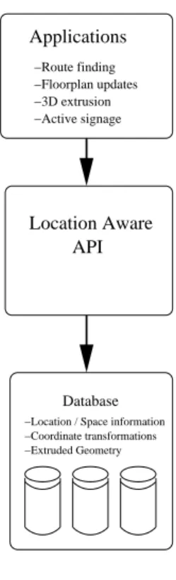
Figure 1-2 shows the overall view of the system architecture; clients communicate with the Location Server using a standard network supporting TCP/IP.
Sometimes a client will desire to place a high-level library between itself and the relatively low-level functionality of the Location Server. Our Location Aware API Standard Library (Section 2.5.2) provides this functionality. Such a library was developed so that developers do not have to “reinvent the wheel” when trying to write applications, such as route finding applications, which seek to exploit the interfaces and data structures we provide. The Standard Library helps map high-level functions
−Route finding −Floorplan updates −3D extrusion −Active signage API Location Aware Applications Database −Location / Space information −Coordinate transformations −Extruded Geometry
Figure 1-2: System Architecture of the Location Aware API
and algorithms to low-level chores like retrieving and representing Space data and exploring adjacent Spaces.
1.3.5
Security and Privacy
Very little state other than the TCP/IP connection is kept in the Location Server; this makes our Location Server relatively passive with regards to tracking clients. An active, object tracking application would be quite orthogonal with respect to our API. A Location Server could facilitate such a system, but cannot enable one on its own. Our (relatively) stateless server is thus usable in environments where security and privacy are desired.
Our API’s privacy policy matches quite well with the Cricket location-aware hard-ware that complements it (Section 2.2.2). Cricket receivers passively observe station-ary beacons to deduce their position; the stationstation-ary Cricket infrastructure does not actively track users of the system. Clients can use Cricket to figure out their location and the Location Aware API to determine information about their surroundings, with a high degree of anonymity.
1.4
What the API Does Not Provide
This API provides a simple, standardized way to access campus building geometry and adjacency data. Although it was designed with route finding as the defining ap-plication, it does not require the Location Server to provide any algorithms. We have provided route finding, utility functions, and other algorithms as part of a standard library, useful for clients of the API.
This API also does not enforce any particular method of storing data, or a specific database schema. Indeed, our implementation does not even have a backing database; we load our campus building data from standard ASCII text files in a proprietary for-mat. One downside to storing data this way is that a change to the building data text files requires a complete Location Server restart. Of course, a live implementation of the Location Server with many concurrent users will probably need an incrementally changeable, robust relational database as the backend to improve performance.
Our API supports the idea of virtual tags; a robust, flexible method for specifying the positions of objects. The Location Server is expected to maintain lists of Virtual Tags within Spaces, but associating Tags with physical objects, tracking objects, or maintaining other physical state is the job of other systems designers. This API could be used to help track objects (or people), but only by supplying Space geometry and adjacency information. Security, privacy, and other policy issues are immediate concerns with tracking systems; these can safely be ignored here.
Our API does not support automatic resource or service discovery; this is the job of a complementary system such as the Intentional Naming System (INS) [1]. Such a system allows mobile software clients to search for and discover software services based on a variety of criteria, including geographic location. For example, this would allow a handheld computer user to ask the network for the (geographically) nearest printer server or active sign; services within a certain distance would appear to the user automatically to activate. This is a powerful example of Location Aware Computing; our API would work in concert with a modified version of INS, providing Location and Space data, enabling this geographic mapping of services.
1.5
Related Systems
Research into the development of location aware hardware and software systems has accelerated recently, fueled by the decreasing size of mobile hardware. Here, we discuss several competing systems,
1.5.1
GIS with Route Finding
Geographic Information System, or GIS, is an industry standard method for storing and accessing geospatial data. Usually backed with a database server, a GIS system can store objects with location and spatial attributes, as well as information about object interoperability. This makes it possible for a facility to store data about water pipe locations, for example, allowing the GIS server to infer water flow direction, junction capacity, and other properties of the water system. Objects in a GIS database can also store adjacency attributes, making route finding using only GIS queries an attractive possibility.
GIS has vast capabilities for facilities maintainers who must manage lots of infor-mation about building and grounds infrastructure. The new OpenGIS consortium [3] promises to publish freely available GIS standards, allowing clients on any platform to exchange GIS data and GIS services.
The Location Aware API is already an indirect abstraction over MIT’s GIS server data. The BMG pipeline (Section 2.2.1) pulls CAD documents from the GIS database, feeding the data into the LocationServer backend. Our API provides a much simpler interface to the GIS spatial data than GIS itself, lowering the memory, processing, and bandwidth requirements of Location Aware clients. In the future, the Location Server will evolve to become a more direct client of MIT’s GIS, extracting data directly from the GIS servers without the intervening BMG pipeline.
1.5.2
Drishti: Navigation for the Blind
Drishti [6] is a location-aware computing platform designed to aid sight-impaired people with outdoor navigation. It is designed around a portable personal computer running the Windows 98 operating system, with voice recognition software. It accesses geospatial data from the University of Florida Physical Plant’s GIS database via a commodity 802.11b wireless network.
Drishti can use GIS data to do real time route planning and hazard avoidance. For example, it can avoid busy intersections during peak traffic hours, giving the visually-impaired a safer route at certain times of the day.
The Location Aware API can provide a service similar to the Drishti platform but on much more modest hardware. The memory and bandwidth requirements of Drishti make the current implementation weigh several pounds, with limited battery life. Our minimal target is a handheld computer or cellular phone; future prototypes will hopefully showcase the Location Aware API on very resource constrained computing
Chapter 2
Location Aware API
This chapter gives a detailed discussion of the Location Aware API, client and server implementation concepts, and relevant algorithms. First, we discuss the requirements that the API is designed to meet. Then, we explain both BMG, which feeds data to the Location Aware API server, and Cricket, a location aware hardware system. Finally, we focus on the details of the server implementation and talk about the algorithms and Standard Library functions needed by clients.
2.1
Requirements
The Location Aware API is intended to aid location aware devices, serving indoor geometry, resource, and adjacency data in a standardized way. Its minimal intended hardware platform is any device with a TCP/IP stack, and with enough CPU and memory to store and process a few hundred bytes of data per Space. This would allow handheld computers to access indoor geometry data and display or process it in real time. However, the API and associated data structures can also be used to visualize campus data on high-end graphics workstations. The CampusMap client described in Section 3.2 is one example of this; it gathers data from the Location Server and builds a real-time interactive campus map, complete with route finding capabilities.
The Location Server should also have the ability to update transient information about the campus model in real time. For example, a client should be able to tell the Location Server the instant that a certain door is found to be locked (perhaps from a piece of automated door sensing hardware). The Location Server should then be able to update the corresponding Portal’s weight value (to a large or infinite value) so that clients performing route finding can route around the obstruction.
2.2
Supporting Projects
The Location Aware API was influenced and supported by two complementary projects: BMG and Cricket. In fact, one way to summarize the goals of the Location Aware API is the building of an interface between location-aware, Cricket-enabled hardware devices and the BMG geometry database. Many of the features of the Location Aware API were designed with both Cricket and BMG in mind.
2.2.1
The BMG Project
Our API’s usefulness would be quite hard to prove without real-life data to test it with; the Building Model Generator (BMG) project [8] provides an extensive, three-dimensional model of campus, complete with Space adjacency information.
The goal of the BMG project is to build a model of campus using only MIT’s vast database of CAD floorplans, which describe the floor layout of each building. A pipeline of non-interactive command line tools processes each CAD file, groups it with other CAD files from the same building, extrudes the three dimensional geometry, and places it into global (campus) coordinates.
The BMG project’s goals are facilitated by some key features of the MIT floor-plans:
• Each room has exactly one floor-unique name assigned to it, usually with a named point within the room’s boundary. The BMG project can associate this name with the other room data.
• Each room in a floorplan is defined by a fully connected polyline, with other internal polylines restricting access to certain areas of the floor. This is exactly the definition of a Space’s two-dimensional floor boundary in our API.
• Adjacent rooms can be connected by a recognizable door icon, consistent across most floorplans. They can also be implicitly connected by sharing an edge but not a separating wall (an effective portal). This is critical data for the Location Server, since it allows clients to ask questions about Portals and iteratively build an entire campus model, if necessary.
• A campus basemap CAD file exists that specifies the transformation (rotate, scale, and translate) of Space geometry data from local to global coordinates. The campus’s corpus of CAD data enters one end of the BMG pipeline; the result is a directory full of plain text files in a simple, specified format. Our Location Server
implementation (JavaLocationServer.java and others) can read the files from this directory, construct internal data structures, and serve requests from clients.
Our API provides a simple, well-defined abstraction over this mass of geometry data. We formalize the notions of “Space,” “Portal,” and “Location,” providing the user with structured, easily accessible data (see Section 1.3.2).
Because the BMG project’s data has been so useful for this project, we recom-mend that others who implement a Location Server for their facilites follow a similar approach to generating campus data; a non-interactive pipeline simplifies campus updates by allowing changes to campus CAD to automatically propagate.
2.2.2
Cricket and GPS
The Location Aware API was designed to work well with clients who can determine their Space and Location and update them in real time. The Cricket indoor navigation system ([10] and [11]), is particularly well designed for the Location Aware API. This section also discusses the Global Positioning System (GPS) [5], a popular commercial system for outdoor position tracking.
Cricket consists of stationary beacons positioned around the indoor environment, which transmit both radio-frequency (RF) and ultrasound signals. This allows a user with an appropriate sensor to determine both his position and room name in real time. The radio-frequency signal is overloaded with several important pieces of information:
• The identity tag of the transmitter
• The transmitter’s position (in a Cricket-standard coordinate system)
• Space name information, allowing determination of one’s Space without having to do positional calculations.
One can determine a distance to each transmitter by using the speed difference, and thus the difference in arrival times, between sound and radio waves. Signals from multiple transmitters can be used to refine position estimates using various techniques.
Cricket is an ideal match for this API because it allows clients to determine both their Location and Space independently of the Location Server. This is superior to a Location-only system, such as GPS, because a client can confirm the accuracy of Location information using Space sensing (via the radio signal). A Location sample
can have a large probability distribution if the environment electrically or ultrasoni-cally noisy; a corresponding Space sample can help clients accept or reject Location measurements very close to Space boundaries. Also, clients of Cricket may find Space information to be useful, even though they are not connected to a Location Server. Miu calls Cricket a “Spatial Information Service” ([10] p. 35) because of its ability to deliver Space information data.
More recent versions of Cricket are beginning to support directional as well as positional data [2]; this is the infancy of the previously mentioned software flashlight (Section 1.2.2). Since our notion of Location inherently includes a direction, we are ready to take advantage of this new hardware capability in future versions of both Cricket and the Location Server.
Cricket is also an example of useful Location Aware hardware since it works in-doors, where the bulk of our geometry data resides. GPS is of only limited usefulness, since it cannot penetrate dense indoor environments. Eventually Cricket and GPS will become a more unified hardware platform; Cricket will use GPS measurements from exterior doors and windows, propagating the universal GPS coordinate system to all indoor Cricket beacons. Cricket may eventually incorporate both commodity GPS hardware and the existing location-sensing system into the same compact de-vice. This would allow Location Aware clients to work indoors and out with the same coordinate system.
2.3
API Details
This section gives further details about the implementation of the Location Aware API. Here, we detail our concrete implementations of Location Server in the Java programming language, as well as examples of client programs. We also talk about various useful client algorithms and show how the Location Aware API Standard Library presents a high level layer over our low level API.
2.3.1
A Network API
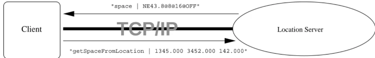
The Location Aware API is intended to be a network API: a service which provides information about Spaces and Portals using a network socket and standard data format. However, for clarity, we will present API functionality as object-oriented methods. Each method of the Location Server corresponds to a command sent by a client over the network and a response by the server. One example is the getSpace
Client
"getSpaceFromLocation | 1345.000 3452.000 142.000"
Location Server
"space | NE43.8@8@16@OFF"
TCP/IP
Figure 2-1: Over the network: a client request and a server response. The client first sends the command “getSpaceFromLocation”, a delimiting character, “|”, and the location information serialized with a standardized format (see B.2). The server then sends a response code “space”, a delimiting character, and the formatted Space name.
command (Figure 2-1), in which the client sends a Location (coordinates) and receives a Space name, with which he can make further queries.
This network exchange is analogous to a Java method called getSpaceName, which takes a Location object as an argument and returns a String holding the Space name (Figure 2-2).
interface LocationServer { ...
public String getSpaceName(Location location); ...
}
Figure 2-2: The getSpace request recast as a Java method signature.
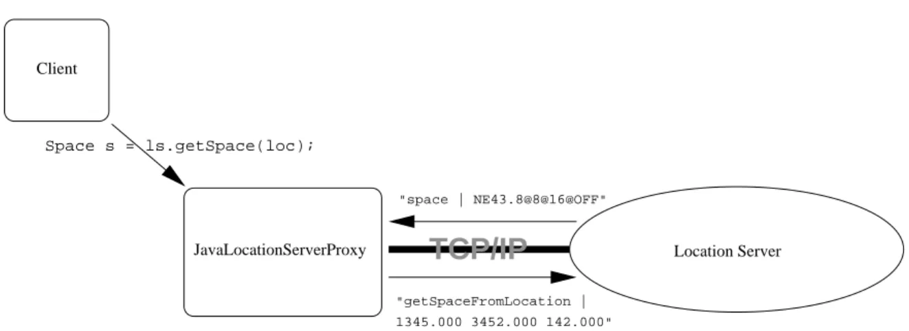
Using functional notation to describe our network API is preferred because it provides a more easily readable, simpler abstraction than network protocols. Also, clients will most likely use a functional language as a high-level layer between the Location Server and the rest of the application (Figure 2-3).
Much of the development of the API and various clients took place before the network protocol was even defined; the Location Server was simply a Java class with several methods providing the necessary functionality. Our network protocols are thoroughly defined in Appendix B.
2.4
Server Implementation
This section discusses three different Location Server implementations: one straight-forwardly written as an ordinary Java class, one extended using Java’s remote method
JavaLocationServerProxy Client Location Server "space | NE43.8@8@16@OFF" "getSpaceFromLocation | 1345.000 3452.000 142.000"
TCP/IP
Space s = ls.getSpace(loc);Figure 2-3: Java, a functional language, providing a high-level layer between the network protocol of the Location Server and the client
invocation (RMI) capabilites, and one that acts as a network server using TCP/IP. The third implementation is this project’s original goal; a network server following the well defined network API described in Appendix B. Such a server is cross plat-form, working with any O/S and hardware combination that can read bytes from a TCP/IP connection. It fulfills one of our basic requirements - that even embedded platforms with very limited resources can query the server to obtain desired Space and Portal information.
2.4.1
Java Class
The very first definition of a Location Server, the properties of Spaces and Portals, and the interpretation of our BMG data, occurs in three main classes: Location, Space, and Portal. The full public API of these classes is contained in Appendix A; this section discusses only a fraction of their full functionality.
The Java Class Location Server, or JavaLocationServer implements a simple interface, LocationServer:
public interface LocationServer {
public Location getLocation(Space space); public Space getSpace(Location location); public Space getSpace(Location location,
String buildingName, int floor); public Space getSpace(String spaceName);
public Portal getPortal(String portalName); }
2.4.2
Java Class - RMI Server
The first step towards network-enabling a LocationServer was to have it function via Java Remote Method Invocation (RMI). We did this by making LocationServer extend java.rmi.Remote:
...
public interface LocationServer extends java.rmi.Remote { ...
and giving each method the capability to signal a server or network error: ...
public String getSpaceName(Location location) throws RemoteException ; ...
These were the only changes to LocationServer that were necessary to enable RMI in all implementing classes.
The new implementing class is called JavaLocationServerRMI, and it works nearly identically to JavaLocationServer. Clients remotely invoke the getSpace and getLocation methods to retrieve desired Space and Location information. They must also handle RMI exception events, since the Location Server is now accessed via the network.
Space.java and Portal.java both define classes which are fully serializable by Java; that is, the Java environment can automatically convert Space and Portal ob-jects to and from streams of bytes. This means that a client running in one JVM (Java Virtual Machine) can call methods on a JavaLocationServerRMI running in another JVM and transparently receive any returned objects. Each JVM handles the conversion of method arguments and return values into byte streams and passes the values over the network. The result is a networked Location Server that still has most of the abstraction benefits of a locally running class. See A.2 for details on the startup procedure and initilization code necessary to get two JVM’s communicating via RMI.
JavaLocationServerRMI hides much of the functionality of a true, cross-platform implementation which communicates only via byte streams. Not only are the proto-cols for getSpace(Location location) and getLocation(Space space) hidden be-hind the corresponding JavaLocationServer methods, but geometry queries, Space-name formatting, and other queries are hidden in the object-oriented abstraction of the Space and Portal classes. Space and Portal are classes that hold Space and Por-tal information in object memory, accessible by a simple method call. For example, Space.java has the following method:
1. public Collection getPortals() { 2. Vector returnVector = new Vector(); 3. Iterator i = portals.iterator(); 4. for (;i.hasNext();) {
5. returnVector.add(locationServer.getPortal((String)i.next()));
6. }
7. return (Collection) returnVector; 8. }
This method takes no arguments and returns a Java Collection of Portal. A Java Collection is an abstract data type which can contain Portal objects.
The method first constructs a new Collection on the heap. It then iterates through the Portal names contained within the Space object, copying and inserting them into the new Collection. Then, the new Collection is returned.
Given only the network protocol, this method would have to work quite differently. A new Collection would still be constructed and returned, but instead of filling it with Portal names from the object’s internal memory, the remote Location Server would have to be queried for the Space’s Portal names.
It may be beneficial for clients to implement Space and Portal even when using a true network server, since they encapsulate so much data behind an object-oriented abstraction. The JavaProxyServer (Figure 2-3) would translate Location Server network streams into live Java objects which can be referenced by clients.
2.4.3
Network Server
Our network server is based on the same code as the original Java class server and Java RMI server. The main difference is the implementation of the network protocol, which enables clients to retrieve Space and Portal data using network requests.
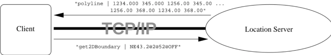
Client
TCP/IP
"get2DBoundary | NE43.2@2@52@OFF"
Location Server
"polyline | 1234.000 345.000 1256.00 345.00 ... 1256.00 368.00 1234.00 368.00"
Figure 2-4: A client requests a Space’s polygon
Instead of returning Space and Portal information with a method return value, the network server receives network requests, serializes the information using the protocol defined in Appendix B, and returns the data via a TCP/IP connection. Figure 2-1 illustrates the process of communicating with the network server.
Our network server is implemented in the Java programming language, in the file JavaLocationServerNet. It extends (in an object-oriented sense) the original JavaLocationServer and adds three methods: a Main method, allowing it to run as a stand-alone program, and the receiveRequest and sendData methods, allow-ing network communication. These additional methods are defined in the interface NetworkServer, which is implemented by JavaLocationServerNet. For this reason, our new class can serve as both a network server and a standard Location Server, and can access the same internal data structures defined in JavaLocationServer.
The receiveRequest method parses the client request, which is passed from the operating system’s network layer to the Java String in the method argument. The first part of any client request is analogous to the method name in JavaLocation-Server; it tells the server what information is requested. This is followed by a delimiting token (a ’|’ in Figure 2-4), and any further argument information. For example, Figure 2-4 shows a get2DBoundary request, in which a client requests the polygon that defines a Space’s two-dimensional floor boundaries.
The server returns the information requested by the client, first retreiving Space and Portal data from its internal memory structures. Recall that JavaLocation-Server constructs its memory structures from ASCII files generated by the BMG pipeline (Section 2.2.1); JavaLocationServerNet reads its data in the very same manner.
The sendData method converts information from Java objects into bytes which are then sent by the network layer. In the example shown in Figure 2-4, the network server first sends an identifying token, polyline, a comma separator, and then a series of ASCII formatted double-precision real numbers representing the x-y values
of the points making up the polyline. Finally, the request is ended with the end token. Other network requests are detailed further in Appendix B. The complete func-tionality of the Java defined API is reflected in the network API, allowing clients using any language or operating system to access our data.
2.5
Client Details
This section explains some of the algorithms and design decisions encountered in building several proof-of-concept Location Aware clients. The subsequent discussion will focus on the Java class implementation of the Location Server and its methods, rather than the (functionally identical) network API.
In this discussion, we assume that a client has both a connection to a Location Server and access to some sort of Location aware hardware (like Cricket, section 2.2.2). Minimally, any client must be able determine the name of the Space in which it currently resides; a stationary client can hard-code a current Space name.
The client must be able to ask the Location Server for the properties of its current Space so that an adjacency graph can be built incrementally. For example, a client may wish to enumerate every single Space so it can display a high level picture of campus. It must do so by first starting with a campus Space name, asking for its Portals, finding the Spaces that connect with those Portals, and so on (Figure 2-5). In this way, it can save a complete model of campus in its internal memory structures. The Location Aware API can only provide information about a Space if the client has a valid Space name. Space names are obtainable two ways: by requesting a conversion from a Location or by walking the graph of adjacent Spaces connected by Portals. Thus, a second method for enumerating every Space on campus is to provide a finely sampled grid of campus Locations, eliminating duplicate Spaces. The Location Aware API Standard Library, explained in Section 2.5.2 and Appendix C, provides some methods to help clients with this and other tasks.
2.5.1
Algorithms
A variety of algorithms are important when constructing Location Aware API clients; most of these are focussed on efficient methods for route finding and path plotting. The most useful algorithms that we studied will be discussed in detail; alternate algorithms that were not used will also be touched upon.
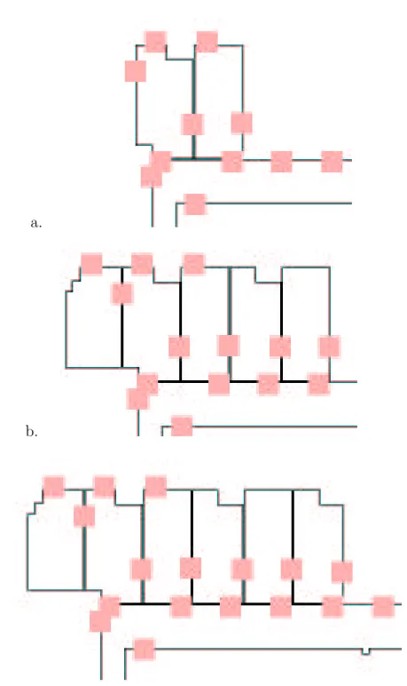
a.
b.
c.
Figure 2-5: A client incrementally explores the campus map depth-first. Each step shows the discovery of additional Spaces.
Library (section 2.5.2); all of the method signatures in this section correspond to functions described in Appendix C. We assume that the reader is familiar with basic graph algorithms, since we present route finding in terms of walking graphs defined by edges (Portals) and nodes (Spaces). The words edge/Portal and node/Space will be interchanged when talking about route finding in this section. We will also use the term route exclusively when mentioning connected paths from one Space to an-other, and path when talking about paths within a single Space, consisting of several connected Locations.
Route Finding
Route finding algorithms are definitive challenges for this API, since almost every client will use route finding to extract information about its surroundings. Recall that the Location Aware API is particularly suited to route finding because of its emphasis on room adjacencies; Spaces are made adjacent to one another by sharing references to Portals. Portals have both a Location and a weight, analogous to an edge weight in a standard graph data structure.
An interesting feature of our API is that Spaces also have weights associated with the cost of travelling from one Portal to another. This means that minimal cost paths can also be computed for the dual of our Space-Portal graph, in which Portals are nodes and Spaces (actually, paths between Portals) are edges. This is probably a better way to find routes where a person must reenter a Space more than once. Section 4.1 discusses this future enhancement to our route finding algorithms. Simple searches: Breadth-first and depth-first The most easily implemented way to do route finding is a straightforward breadth-first or depth-first search. This is because the client can construct the adjacency graph structure of the Spaces and Portals by incremental discovery. The client first asks the Location Server for a Space, asks for its Portals, and then requests the Spaces connected to those Portals. This is exactly the definition of a breadth-first search (Figure 2-6).
During a breadth-first search, the client expands a Space by first requesting its Portals, asking for the next adjacent Spaces, and then iteratively expanding those Spaces in turn.
A client may use a depth-first search if desired; this is similar to a breadth-first search, but each Space is immediately expanded upon discovery. This leads to very “deep but narrow” intermediate paths while the algorithm is in progress (Figure 2-7). Using either of these methods, a client will eventually discover the entire graph of
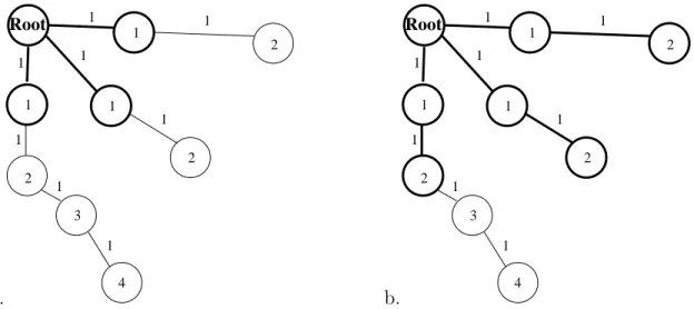
a. 1 3 1 1 1 1 1 1 2 2 2 1 1 1 1 Root 4 b. 1 3 1 1 1 1 Root 1 1 1 1 4 2 2 2 1 1
Figure 2-6: A graph is explored breadth-first. Each node is labeled with its distance from the root. (a) shows the graph with explored nodes and edges darkened. (b) shows the graph after a breadth-first iteration.
connected Spaces. It can store the graph in its internal memory structures for further analysis, such as performing optimal searches. Alternately, a client can perform a non-optimal search with these algorithms, stopping upon discovery of a “final” Space or other criteria. For optimal searches, Dijkstra’s algorithm is quite useful.
Dijkstra’s algorithm This section briefly discusses Dijkstra’s algorithm, an effi-cient algorithm for computing shortest routes from one Space to another.
Dijkstra’s algorithm requires the use of a priority-queue Q, which maps a weight to each resident object, and also supports an Extract-Min method, which returns and removes the object with the lowest weight. Dijkstra’s algorithm also keeps a pointer to a set S of Spaces for which the minimum route cost has already been determined.
The following pseudocode describes Dijkstra’s algorithm. It has been adapted from [4] p. 527, which also contains a proof of its correctness.
Dijkstra(start)
1 Insert(Q, start, 0) . The start Space has a zero distance to itself 2 while (Q 6= ∅)
3 u← Extract-Min(Q)
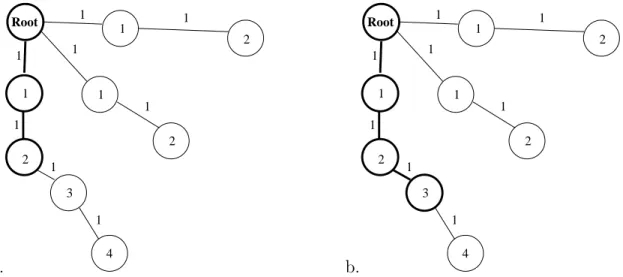
a. 1 1 1 1 1 1 1 4 Root 3 1 1 2 2 2 1 1 b. 1 1 1 1 1 1 1 4 Root 3 1 1 2 2 2 1 1
Figure 2-7: A graph is explored depth-first. (a) shows the graph with explored nodes and edges darkened. (b) shows the graph after a depth-first iteration. Notice that the explored path tends to extend narrowly from the initial Space.
5 for each Space v adjacent to u
6 if minimum cost c to v can be improved
7 Previous(v) ←u
8 Insert(Q, v, c)
Lines 6 - 8 perform the relaxation step of the algorithm. Optionally, we can terminate the algorithm when S is updated with a goal Space on line 4. However, it is often desirable to let the algorithm compute the single-source shortest paths to every reachable Space; see Section 3.2.2.
A* search Another algorithm, the A* search algorithm, is often used in shortest-path problems. It is similar to Dijkstra’s algorithm, but it uses a different mapping in the priority queue: the sum of a heuristic distance estimate and the current shortest path distance. A* “expands” nodes that have the shortest distance potential first; geographic map problems with a simple (Euclidean distance) potential heuristic are particularly well suited for this algorithm.
We decided not to implement A* search for this project for three reasons:
1. The Location Aware API does not (currently) support a heuristic estimate of total path distance. This may not ever be possible, since Space and Portal weights can change unexpectedly and in real time.
Figure 2-8: A simple polygon (outline, in bold) and its Delaunay triangulation (inter-nal triangles). Triangles are offset from polygon outline and other triangles for clarity
2. Unlike Dijkstra, A* locks the user into a specific finish Space
3. Our Space adjacency graph is not dense enough to require heuristics to narrow the search space.
Polygon Triangulation
Polygon triangulation is an important algorithm, useful for clients who need to per-form a more detailed analysis of a Space’s two-dimensional polygonal boundary. With such an algorithm, a client can decompose the polygon into non-overlapping trian-gles. It is important to note that the Location Aware API does not provide a Space’s boundary triangulation for two important reasons:
• Too much additional API complexity: defining a triangle, defining the triangu-lation’s properties, forcing implementors to add yet another algorithm.
• Computing a triangulation is fairly computationally expensive; the Location Server should probably conserve computational resources to handle client re-quests.
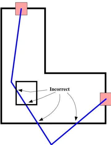
Incorrect
Figure 2-9: An illegal path through a polygon - it exits the border and crosses into forbidden areas.
However, we do currently provide triangulation algorithms in the Standard Li-brary. Our Java triangulation code is based on Dani Lischinski’s Constrained Delau-nay Triangulation (CDT) package [9]; we use native methods to translate between CDT’s C++ API and Java.
It’s important that we use a constrained triangulation; the polygon’s edges define a set of constraining edges, each of which must be a member of a resulting triangle. No triangle may have an edge that intersects a constraining edge. Optionally, one can define additional constraining points, each of which is a member of at least one resulting triangle. A constrained triangulation, with or without additional constrain-ing points, allows us to completely tile the floor of a Space, guaranteeconstrain-ing that each triangle is in the Space’s interior (Figure 2-8).
Polygon triangulation is particularly useful for clients who wish to find a path from one point to another within a Space. Often, a client needs to find a short path through a Space which avoids crossing outside edges of the polygon, as well as any internal polygonal regions which are off limits (Figure 2-9).
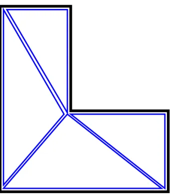
Figure 2-10: A simple polygon, triangulated, with a short path from one border location to another.
We specify such a path as a sequence of Positions; this sequence implicitly defines a path connected by straight line segements. The remainder of this document assumes that paths within Spaces are specified in this manner.
We can guarantee a correct path within a room after triangulation by using the following algorithm:
1. Find the triangle whose center is closest to the starting Location. For interme-diate Spaces, the starting Location will be a point in the previous Portal. This is the start node.
2. Find the triangle whose center is closest to the end Location - this is the end node.
3. Triangle centers form nodes in an adjacency graph. Common sides between tri-angles are undirected graph edges. Use a shortest path algorithm like Dijkstra’s to find a sequence of triangle centers that make a shortest path
4. The plotted path (sequence of Locations) consists of each triangle center pre-ceded and followed by the midpoints of the shared triangle side
a. b.
Figure 2-11: The RouteFinder GUI. Part (a) shows the paths with polygon triangula-tion, part (b) without. Part (c) shows the same route with iterative filtering applied.
Figure 2-12: Our path-finding algorithm works quite well, correctly traversing the curved hallway. Notice that the path is sometimes quite erratic.
This algorithm gives a relatively short path through a room. The line segments implied by the Location sequence do not intersect any forbidden regions; this is because the line segment endpoints are necessarily on the edges or in the interior of the triangles, which lie within the polygon. Figure 2-10 illustrates a short path within a Space with the accompanying polygon triangulation.
To plot an entire route from one Space to another, first we use a Standard Library function to find a list of Spaces giving an efficient route from the start Space to the finish Space. Then, we can triangulate each intermediate Space, drawing a short route between a Space’s appropriate portals. The RouteFinder client’s GUI is a good illustration of this technique (Figure 2-11).
Notice that this algorithm produces a very good path through an oddly shaped room, even following a curving hallway without exiting the Space (Figure 2-12). However, the triangulation is very coarse when the polygon has few defining segments, and some odd effects can result (Figure 2-13). Here, the path winds around on itself,
as a result of the first triangle being in the opposite general direction of the destination portal.
The path plotting can be greatly improved by the process of path filtering. Path Filtering
Path filtering within a Space is usually necessary due to the simplicity of a typical floor boundary; most Space boundary polygons define few constraining edges, limiting the number of resulting triangles. A small number of triangles yields paths that have poor, jagged resolution, since the resulting path line segments can only be bounded by triangle centriods or edge midpoints. Jagged paths are a problem for clients who need to display approximate directions to another location. In some cases, paths can start out pointing in the opposite of the recommended direction (Figure 2-13)!
Shorter and smoother paths can be generated using a process Allen Miu terms path smoothing ([10], p. 49). Here, we discuss Miu’s approach, along with several new approaches, collectively termed path filtering. Each of these path filtering techniques can be used alone or in combination to improve the quality of the returned path.
Miu suggested “replacing every sucessive pair of path segments with a new seg-ment joining the mid points of the segseg-ments that are being replaced” ([10], p. 52). Intuitively, this tends to “average the slopes” of sucessive segments with opposite signed slopes. This approach yields very good results, especially with repeated itera-tions. However, this method can produce invalid paths, since sucessive line segment midpoints may cross polyline boundaries, especially around sharp corners. See [10] p. 51 for illustrated examples of Miu’s technique.
Our approach, implemented in the Standard Library, is what we call iterative shortening. This algorithm seeks to elminate as many intermediate Locations as possible, reducing the overall complexity and length of the path, but guaranteeing correct output . The following pseudocode illustrates the algorithm:
Iteratively-Shorten(P,S)
1 Keep(P[0]) . Always keep the first Location 2 A← P [1]
3 p← P [1]
4 for i ← (2 to P.length − 1)
6 if (nA ∩ ab ∀ ab ∈ S)
7 .if n and the anchor point intersect with any line segment in S 8 Keep(p) . Store previous point
9 A← p . make it the new anchor
10 p← n . Update the tracking of previous Location
The inputs are the array of Locations defining the path, P and the Polyline surround-ing the Space, S.
We iterate through the list of line segment endpoints (Locations), keeping track of an anchor point, A, the next Location, n, and the previous Location p. We skip n if the anchor point A and n define a legal line segment. If A and n define an illegal line segment, we store p, since it is the last known legal segment. We then make A← p and begin testing subsequent Locations starting at A ≡ p. The resulting path is necesarily shorter if any intermediate endpoints are skipped; this is a consequence of the triangle inequality. 1
Iterative shortening can improve any correct path; the output path will be ei-ther the same as the input or shorter. See Figure 2-14 for an example of iterative shortening.
One algorithm that can yield smoother paths is interpolation and resampling. We can interpolate our path points with a cubic spline or other smooth curve, returning additional points evenly spaced along the curve. This has the attractive consequences of both smoothing the path and giving a more consistent length between consecutive Locations. Figure 2-15 illustrates the results of this technique.
2.5.2
Convenience Functions - the Standard Library
One intended feature of the Location Aware API is its simplicity - it is inherently a low-level API, meant to support clients on handheld computers with minimal hard-ware requirements. Most high level functionality, such as route finding, is not available in the core API. Therefore, as a proof of the Location Aware API’s usefulness, we have developed a Standard Library - a higher level abstraction over the basic functionality of a Location Server. The standard library includes utility functions, remapping low level calls to more useful high level calls; algorithms, such as route finding, and exam-ple imexam-plementations of a Java language Location Server. This section will focus on
1The triangle inequality states that any side of a triangle is shorter than the sum of the other two sides. In other words, for any sides a, b, and c, 0 <|a| < |b| + |c|.
a.
b.
c.
Figure 2-13: Legal, but unnecessarily twisty Space paths (a) with and (b) without triangulation. (c) shows the path after iterative filtering, which removes the twist.
a. b.
Figure 2-14: A path (a) is iteratively shortened, resulting in (b). Endpoints marked with an ’X’ are eliminated, and their adjoining line segments condensed into a single segment.
a. b.
c. d.
Figure 2-15: The path from Figure 2-10 (a) is cubic spline interpolated (b) and resam-pled at a constant segment length (c). Part (d) shows the new endpoints connected with line segments
implementation and interface details, rather than the more general, design-oriented algorithms discussion in Section 2.5.1.
Utility Functions
Utility functions exist to give our fairly low-level API some of the high-level features a client might desire without polluting the Location Server interface with too many functions. Some very complex algorithm implementations, such as route finding, are discussed in Section 2.5.2; here we focus the utility functions.
The full descriptions and method signatures of all the various utility functions is given in Appendix C. Here, we touch on some of the more important ones.
getBestPortals Often, a client will have three consecutive Spaces known to be part of a path. To draw a path through the middle Space, the beginning and end portals must be determined, since the Space may have many portals not adjacent to either the start or end Space. The function getBestPortals returns two portals linking the three Spaces, finding the pair that gives the shortest path through the middle room. It finds the path from portal to portal by using the getShortestRoute function. getShortestRoute This function takes two Positions and a Space as an argu-ment; it returns a Java Collection of Positions representing the triangulated short-est route through the room. This is one of the most complicated utility functions; it internally defines a Triangle with various useful properties. It then does triangulation of the Space’s border polyline, edge matching for the entire triangle collection, and Dijkstra’s algorithm to find the shortest route.
The returned path is the result of the centroid-midpoint-centroid path finding algorithm previously discussed in Section 2.5.1. getShortestRoute also performs path filtering by iterative shortening (Section 2.5.1).
getSpacesExcludingWithWeights This function performs an important high level operation; it finds a list of Spaces adjacent to a given Space, excluding a list of Spaces given as an argument. It also returns the weight associated with travelling through a Portal into each adjacent space. If there is more than one Portal leading to an adjacent Space, it returns the minimum Portal weight.
This is an important operation in nearly every route finding algorithm; the follow-ing is a few lines from our implementation of Dijstra’s optimal path algorithm (Section 2.5.1), in which the current node (Space) is expanded, or explored for adjacent Spaces:
...
Vector shortestPath = (Vector) nextObject[1]; /*grab the current shortest path from the priority queue */ Space head = (Space) shortestPath.lastElement(); /*we’re expanding
the head of the path */
if (head.equals(space2))
return shortestPath; //are we done?
Collection nextSpaces = getSpacesExcludingWithWeights(shortestPath, head); if (nextSpaces == null) //no more adjacencies to follow
continue; ...
The next steps are to construct new paths from the nextSpaces collection, adding the Portal weights to the new path lengths. This algorithm greatly simplifies the step of exploring a Space to find its adjacencies.
getSpacesOnFloor The getSpacesOnFloor function uses a private, recursive, helper function to do a depth-first exploration of the spaces on a given floor. Whenever a Space on a different floor is encountered (from going up or down stairs, for example), the first recursion is terminated. The function returns after all of the depth-first paths have been explored and terminated; the explored Spaces are returned as a Java Collection.
Currently Implemented Algorithms
Our library currently has implementations for all of the search algorithms and the iterative-shortening path filtering algorithm discussed in Section 2.5.1. This section discusses our implementations in greater detail.
Depth-first and Breadth-first search Our depth-first search algorithm imple-mented in Java is called findRouteDepthFirst. Its arguments are two Spaces: start and finish. The function returns a Java Vector that contains, in order, the sequence of Spaces forming the first path found from start to finish. If finish is not in the adjacency graph, both algorithms return a null pointer, signalling a failed search.