Publisher’s version / Version de l'éditeur:
Proceedings of the IEEE International Ultrasonics Symposium 2009., pp. 629-632,
2009-09-20
READ THESE TERMS AND CONDITIONS CAREFULLY BEFORE USING THIS WEBSITE. https://nrc-publications.canada.ca/eng/copyright
Vous avez des questions? Nous pouvons vous aider. Pour communiquer directement avec un auteur, consultez la première page de la revue dans laquelle son article a été publié afin de trouver ses coordonnées. Si vous n’arrivez pas à les repérer, communiquez avec nous à [email protected].
Questions? Contact the NRC Publications Archive team at
[email protected]. If you wish to email the authors directly, please see the first page of the publication for their contact information.
NRC Publications Archive
Archives des publications du CNRC
This publication could be one of several versions: author’s original, accepted manuscript or the publisher’s version. / La version de cette publication peut être l’une des suivantes : la version prépublication de l’auteur, la version acceptée du manuscrit ou la version de l’éditeur.
Access and use of this website and the material on it are subject to the Terms and Conditions set forth at
Ultrasonic probes simultaneously producing one longitudinal and two
shear waves and their potential applications
Wu, K. -T.; Jen, C. -K.; Kobayashi, M.; Zhao, L.
https://publications-cnrc.canada.ca/fra/droits
L’accès à ce site Web et l’utilisation de son contenu sont assujettis aux conditions présentées dans le site
LISEZ CES CONDITIONS ATTENTIVEMENT AVANT D’UTILISER CE SITE WEB.
NRC Publications Record / Notice d'Archives des publications de CNRC:
https://nrc-publications.canada.ca/eng/view/object/?id=3b629741-59dc-43eb-b2f2-3662f7c1e583 https://publications-cnrc.canada.ca/fra/voir/objet/?id=3b629741-59dc-43eb-b2f2-3662f7c1e583
Ultrasonic Probes Simultaneously Producing One Longitudinal
and Two Shear Waves and Their Potential Applications
K.-T. Wu1, C.-K. Jen2, M. Kobayashi2, and L. Zhao3 1. Department of Electrical and Computer Eng., McGill University, Montreal, Canada 2. Industrial Materials Institute, National Research Council Canada, Boucherville, Canada
3. The State Key Laboratory of Polymer Materials Eng., Polymer Res. Institute of Sichuan Univ., Chengdu, China
Abstract— Ultrasonic probes which can simultaneously generate
and receive two orthogonal polarized shear (S⊥ and S//) and
longitudinal (L) waves in screw shape have been presented. Thick piezoelectric films are directly fabricated onto the heads of
such probes as L wave integrated ultrasonic transducers. S⊥ and
S// waves are obtained using mode conversion method.
Application of such probes for on-line polymer injection molding process diagnostics is demonstrated.
Keywords- Ultrasonic birefringence; integrated ultrasonic longitudinal and shear wave transducer; nondestructive testing; material characterization; process diagnostics
I. INTRODUCTION
Thickness measurement including corrosion and erosion monitoring using ultrasonic technology is routinely used in industries at room or elevated temperatures. Certainly high accuracy is desired. However, factors affecting the measurement accuracy using ultrasound can come from texture [1], [2], stress [1], [3]-[5], etc which all alter the ultrasonic velocities in the material. In the other word, if the thickness of the material is given, ultrasonic velocity variations may be applied to measure the stress and texture [1]-[5]. In [1], effects of statically applied stresses on the velocity of ultrasound in the material were studied at room temperature using the combination of three standard alone ultrasonic transducers (UTs); namely one longitudinal (L), one vertically polarized shear (S⊥) and one horizontally polarized shear wave (S//). The
combination of such three types of UTs at room temperature was also used to measure the residual stress or texture in the textured steel [2], [3]. Furthermore acoustic birefringence involving just S⊥ and S// measurements were also reported [6].
Some of experiments for the above mentioned studies were performed using electromagnetic acoustic transducers (EMAT) [3], [4]. However, EMAT cannot be used to measure the non-conducting substrates, and may be bulky and have low sensitivity.
During industrial material processes such as polymer injection molding (IM) real-time on-line non-invasive ultrasonic diagnostics is much desired [7], [8]. Previous studies have revealed that polymer melt flow, incomplete filling, solidification, part detachment and ejection, etc can be monitored real time during the process using only the L wave probes. In this study new probes which may provide simultaneous measurements of L, and S⊥ and S// waves will be
developed, additional information such as Young’s and shear modulus and anisotropy of the parts may be obtained on-line.
II. THREE WAVE PROBES
Let a Cartesian coordinate system be xyz with the z direction being the through thickness direction or normal direction to a plate of the material, and x and y being the rolling and transverse directions of a plate such as steel, the stress-free velocities for the propagation along the z direction only depend on the texture coefficients W400 and W420 [2]-[5] and are given
in an Voight [9] approximation [3] by ⎥ ⎦ ⎤ ⎢ ⎣ ⎡ − − = = 35 2 16 5 1 2 / 400 2 11 2 , 2 2 h t C C W V L d L π ρ ρ ⎥ ⎥ ⎦ ⎤ ⎢ ⎢ ⎣ ⎡ ⎥ ⎥ ⎦ ⎤ ⎢ ⎢ ⎣ ⎡ − − + = = ⊥ ⊥ 400 420 2 44 2 S , 2 2 2 5 35 2 16 5 1 /t C C W W h VS ρ d π ρ (1) ⎥ ⎥ ⎦ ⎤ ⎢ ⎢ ⎣ ⎡ ⎥ ⎦ ⎤ ⎢ ⎣ ⎡ + − + = = 2 44 2 400 420 // S , 2 2 // 2 5 35 2 16 5 1 /t C C W W h VS ρ d π ρ
where VL, VS⊥ and VS// are the ultrasonic velocity and td,L, td,S⊥ and td,S//, the ultrasonic time delay of L, S⊥ and S// waves in
the substrate with a thickness of h, and C = C11 - C12 - 2C44,
respectively. Let the polarization of S// wave be along the x
direction and that of S⊥ be along the y direction during the
experiments. Using (1), if one adopts an averaging method and knows the signal crystal elastic constants Cij [2]-[5] and the
density ρ of the material in (1), two texture coefficients, W400
and W420, can be calculated from the measured ultrasonic time
delays, td,L, td,S⊥ and td,S//. Also an accurate measurement of the
substrate (plate) thickness, h that is corrected for texture variations may be made [2].
Recently, integrated ultrasonic transducers (IUTs) have been made using the sol-gel based fabrication process [10], [11] consists of six main steps: (1) preparing high dielectric constant lead-zirconate-titanate (PZT) solution, (2) ball milling of piezoelectric PZT powders to submicron size, (3) sensor spraying using slurries from steps (1) and (2) to produce a layer of PZT composite (PZT-c) film, (4) heat treatment to produce a solid composite PZT-c film, (5) corona poling to obtain piezoelectricity, and (6) electrode painting or spraying for electrical connections. Steps (3) and (4) are used multiple times to produce proper film (IUT) thickness for optimal ultrasonic operating frequencies. It is the objective to use such IUTs to
achieve L UTs. The typical PZT-c film thickness in this study is 75 µm. Typically, the measured d33 of this PZT-c film is
about 30 x 10-12 m/V, the Kt about 0.2, the capacitance and the
dissipation factor at 1 kHz are about 0.75 nF and 0.03, respectively, the relative dielectric constant about 320, the density ρ 4400 kg/m3
and the L wave velocity VL about 2200
m/s. Such IUTs has been operated with a center frequency ranging from 4 to 30 MHz. Their ultrasonic signal strength and bandwidth is comparable to those of the commercially available broadband UTs with backing, however, IUTs can be used at high temperatures [11].
The mode conversion from L to S waves due to reflection at a solid-air interface, as shown in Fig. 1, was reported [12], [13]. It means that the L wave IUT together with L-S mode conversion caused by the reflection at a solid-air interface can generate S waves effectively and be used as an S wave probe. Our approach considers a simple way to fabricate the L wave IUT and let the L IUT be in a plane parallel to axial direction of the probe as shown in Fig. 1. The only criterion is that in Fig. 1 Cot θ is equal to Vs /VL so that the mode converted S waves
will propagate in the direction parallel to the axial direction of the probe. In this study, a mild steel with the L wave velocity
VL= 5914 m/s and S wave velocity Vs = 3215 m/s was used as
the probe material. Therefore one can obtain θ = 61.5°. Using the energy reflection coefficient formula reported in [11] the calculated energy conversion rate at θ = 61.5° is 97.2% that is only 0.5% smaller than the maximum conversion rate at θ = 67.4°. In Fig. 1 a 45° angle is also made for the reflection of L wave along the axial direction of the probe as well. The arrangement shown in Fig. 1 enables both L and S waves propagate together along the axial direction of the probe.
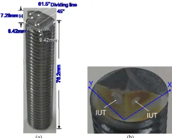
Using the L to S wave mode conversion principle shown in Fig. 1 if one would like to generate two S waves with orthogonal polarizations (birefringence) simultaneously, then θ = 61.5° will be made at two orthogonal edges as shown in Fig. 2. Fig. 2(a) shows an integrated probe having two polarizations and the zoomed probe head is presented in Fig. 2(b). Let one S be the S⊥ polarized in Y direction and the other S// polarized in
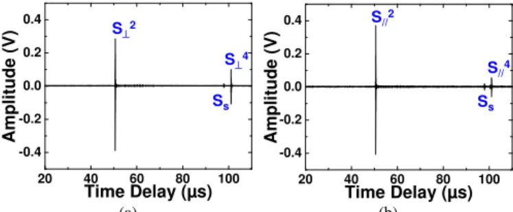
X direction as shown in Fig. 2(a). Figs. 3(a) and 3(b) show the measured ultrasonic signal S⊥n and S//n, respectively reflected
from the end of the probe in time domain and pulse-echo mode at room temperature where the time delay of Sn is that of the nth trip S echo through the probe length plus that of the L wave travelling through the length from L IUT to the steel/air interface. The signal SS indicated in Fig. 3 is a spurious signal
which probably comes from the multiple reflections of L or S waves from an undetermined boundary. The measurement results shown in Figs. 3(a) and 3(b) can be made simultaneously using a two-channel ultrasonic system. During the top electrode fabrication for two IUTs shown in Fig. 2(b), the area of the top electrode and position can be adjusted so that the amplitude ratio of the reflected S⊥2 and S//2can be
adjusted. The center frequency and 6 dB bandwidth of the S⊥2
and S//2 signals are 12 MHz and 11 MHz, and 13.4 MHz and 12
MHz, respectively. Their signal to noise ratios (SNRs) are 36.1 dB and 36.6 dB, respectively. It is noted that such probe may be used as an ultrasonic interferometer which is sensitive to, for example, the anisotropy of the material to be measured, which induces a difference in particle displacement direction or
velocity or both between two S wave propagations along the material. Steel ϕ θ L IUT L 45° S L θ Dividing Line L X Z Y X Air
Figure 1. Reflection and mode conversion with an incidence of L wave at a solid-air interface. (a) IUT IUT X Y 20 40 60 80 100 -0.4 -0.2 0.0 0.2 0.4 (b)
Figure 2. (a) An integrated S wave probe having two polarizations (S⊥ and
S//) and (b) zoomed probe head having two IUTs.
Amplitude (V) Time Delay (µs) S⊥2 S⊥4 Ss 20 40 60 80 100 -0.4 -0.2 0.0 0.2 0.4 (a) Am pl itud e (V ) Time Delay (µs) S//2 S//4 Ss (b)
Figure 3. Ultrasonic signal in time domain of the (a) S⊥ and (b) S// wave
generated by the L IUTs shown in Fig. 2(b) reflected from the end of the probe at room temperature.
If a probe is desired to generate and receive L and S⊥ and S//
signals simultaneously, then one side of the probe shown in Figs. 2(a) and 2(b) can be modified according to the schematic shown in Fig. 1 to achieve such a purpose. In fact, only a slanted surface with an angle 45° is added at such side to reflect the L wave generated by the L IUT or the L wave coming from the reflection at the end of the probe as shown in Fig. 1. Fig. 4(a) shows the integrated probe having three polarizations and zoomed probe head is given in Fig. 4(b). Figs. 5(a) and 5(b)
show the measured ultrasonic signal Ln and S⊥n and S//n,
respectively in time domain and pulse-echo mode at room temperature from the end of the probe. The time delay of Ln is that of the nth trip L echo through the probe length plus that of the L wave travelling through the length from L IUT to the 45° steel/air interface. The measurements results shown in Figs. 5(a) and 5(b) can be carried out simultaneously using a two-channel ultrasonic system. During the top electrode fabrication for the device shown in Fig. 4(b), the area of the top electrode and position can also be adjusted so that the amplitude ratio of the reflected L2, S⊥2 and S//2 can be varied. The center
frequency and 6 dB bandwidth of the L2, S⊥2 and S//2 signals
are 19.1 MHz and 17 MHz, 17 MHz and 16 MHz, and 18 MHz and 17 MHz, respectively. Their SNRs are 23.2 dB, 23.3 dB and 38.4 dB, respectively. (a) IUT IUT Y X (b)
Figure 4. (a) An integrated probe which can generate and receive L and S⊥
and S// waves simultaneous and (b) zoomed probe head having two IUTs.
20 30 40 50 60 70 80 -0.4 -0.2 0.0 0.2 0.4 Amplitud e (V) Time Delay (µs) S⊥2 L2 (a) 20 40 60 80 100 -0.4 -0.2 0.0 0.2 0.4 Amplitude (V ) Time Delay (µs) S//2 S//4 Ss (b)
Figure 5. Ultrasonic signal in time domain of the (a) L and S⊥ and (b) S//
wave generated by the L IUTs shown in Fig. 4(b) reflected from the end of the probe at room temperature.
III. PROBES FOR POLYMER INJECTION MOLDING
The Young’s modulus, shear modulus, Poisson’s ratio, texture, stress and thickness of materials or manufactured parts may be measured concurrently at elevated temperatures by using the ultrasonic probe shown in Figs. 2 or 3 and (1). Fig. 6(a) shows the developed L-S probe and the probe head has been designed as shown in Fig. 1 for real-time non-invasive monitoring of polymer IM process at high temperatures. The
simultaneous generated and received L2 and S2 which were the first round-trip echoes reflected from the bottom of the probe shown in Fig. 6(a) are presented in Fig. 6(b). The developed L-S⊥-S// probe with a probe head designed similar to the one
shown in Fig. 4(b) is given in Fig. 7(a). In Fig. 7(b) four sensor inserts (one L, one L-S, one S⊥-S// and one L-S⊥-S//) are fitted
into a mold insert with electrical connections and this mold insert is then integrated into the mobile mold of a 150 tons Engel IM machine as shown in Fig. 7(b) for on-line monitoring. Ultrasonic signals in time domain of the (a) L and S⊥ and (b) S// wave of the probe shown in Fig. 7(a) reflected
from the end of the probe at room temperature are presented in Figs. 8(a) and 8(b), respectively. L2, S⊥2 and S//2 which were the
first round-trip echoes reflected from the bottom of the probe.
12.7 mm (a) 5 6 7 8 9 10 11 12 13 14 15 Amplitude (a rb. unit) Time Delay (µs) L2 S2 Spurious Signal (b)
Figure 6. (a) a L-S probe and (b) ultrasonic L and S wave signal in time domain of the (a) reflected from the bottom of the probe at room temperature.
Sensor Insert Bottom Surface 12.7 mm (a) (b)
Figure 7. (a) L-S⊥-S// probe and (b) mold insert integrated into an Injection
molding machine. 5 6 7 8 9 10 11 12 13 14 15 Amp li tud e (arb . un it) Time Delay (µs) L2 S2 S⊥2 Spurious Signal (a) 5 6 7 8 9 10 11 12 13 14 15 Amplit ude ( a rb. unit ) Time Delay (µs) S2 S//2 (b)
Figure 8. Ultrasonic signal in time domain of the (a) L and S⊥ and (b) S//
wave of the probe shown in Fig. 7(a) reflected from the bottom of the probe at room temperature.
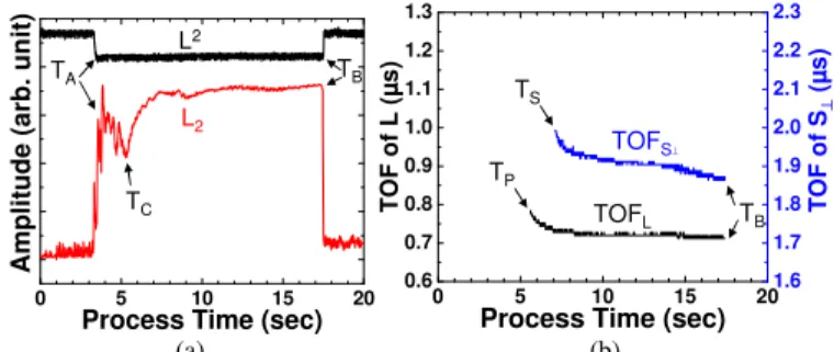
Fig. 9 shows the results of acquired signals with the integrated mold insert probe shown in Fig. 6(a) during the IM process of a HDPE part at 210°C. L2 is the echo reflected at the insert /polymer or air interface depending if the polymer melt existed at the probe location or not. This L2 echo can be obtained regardless of the thickness of the melt. In Fig. 9(a) the timings TA and TB represent the melt flow front arrival and the
HDPE melt arrives at the probe location at TA, the L2 echo
having propagated a round trip through the thickness of the HDPE melt within the mold cavity of 0.75 mm height starts to appear because the probe operates in a pulse/echo mode. When the melt contacts the cold mold internal surface, the melt starts to solidify. Because HDPE is a semi-crystalline polymers the attenuation will reach a peak which causes a dip in the profile of L2 [14]. This dip is indicated at TC in Fig. 9(a). During the
IM, the cavity pressure changes because of the plunger movement [15] the measured time of flights (TOFs) of the L and S waves are shown in Fig. 9(b) after the cavity pressure becomes steady near the timing TP. indicated in Fig. 9(b). The
TOFs of both L and S waves decrease due to the solidification of the melt in the mold cavity in which the L and S wave velocities increase. Since the attenuation of S wave is high in the melt, its TOF can be only observed when the melt solidifies into a viscous condition in which S wave probe has enough sensitivity to detect the round trip echo within the melt as indicated as TS in Fig. 9(b). Assuming the density of the HDPE
during the period between TS and TB be 0.94 g/cm3, the on-line
measured Young’s and shear modulus are shown in Fig. 10.
0 5 10 15 20 Ampl itud e (ar b . un it)
Process Time (sec)
L2 L2 TA TC TB (a) 0 5 10 15 20 0.6 0.7 0.8 0.9 1.0 1.1 1.2 1.3
Process Time (sec) 1.6 1.7 2.0 2.2 2.3 1.8 1.9 2.1 T O F of L (µ s) F of s) TS T O S⊥ (µ TOFL TOFS⊥ TB TP (b) Figure 9. (a) Amplitude variations of L2 and L
2 echoes measured by the mold
insert probe shown in Fig. 9. (b) TOF of the measured L and S⊥. Arrows A and B indicate the time for flow front arrival at probe location.
0 5 10 15 20 0.0 0.2 0.4 0.6 0.8 1.0 1.2 1.4 1.6 1.8 2.0 Mech an ical Mo du lu s (GP s)
Process Time (sec) Shear Young’s
Figure 10. Reflection and mode conversion with an incidence of L wave at a solid-air interface
IV. CONCULSIONS
Integrated ultrasonic S⊥ and S// (birefringence) and L, S⊥
and S// probes have been presented. They were fabricated onto
the heads of steel rods in screw shape through a sol-gel spray technique. The typical PZT-c film thickness in this study is 75 µm. Mode conversion from L to S waves and reflection from a 45° slope for L waves have been used. All the above mentioned probes were operated at room temperature with a center frequency of 12 – 19 MHz, 6 dB bandwidth of 11 – 17 MHz,
and SNR of more than 23 dB. It is noted that these IUTs can operate up to more than 150 °C and 400 °C if bismuth titanate instead of PZT powders are used [11]. Such probes may be used to measure thickness of a sample accurately with a correction of texture including texture coefficients such as W400
and W420. L, L-S, one S⊥-S// and L-S⊥-S// probes have been also
integrated onto a mode insert of a 150 tons Engel Injection Molding machine and real-time non-invasive ultrasonic polymer IM process monitoring was carried out. On-line ultrasonic measurements of Young's and shear modulus have been demonstrated.
ACKNOWLEDGMENT
Authors thank J.-F. Moisan for his technical assistance.
REFERENCES
[1] R.H. Bergman and R.A. Shahbender, “Effect of statically applied stresses on the velocity of propagation of ultrasonic waves,” J. Applied Phys., vol. 29, pp. 1736-8, 1958.
[2] A. Moreau, D. Levesque, M. Lord, M. Dubois, J.-P. Monchalin, C. Padioleau and J.F. Bussiere, “On-line measurement of texture, thickness and plastic strain ratio using laser-ultrasound resonance spectroscopy,” Ultrasonics, vol. 40, pp. 1047-1056, 2008.
[3] D.R. Allen and C.M. Sayers, “The measurement of residual stress in textured steel using an ultrasonic velocity combinations techniques,” Ultrasonics, vol. 22, pp. 179-188, 1984.
[4] R.B. King and C.M. Fortuko, “Determination of in-plane residual stress states in plates using horizontally polarized shear waves,” J. Appl. Phys., vol. 54, pp. 3027-35, 1983.
[5] M. Hirao, K. Aoki and H. Fukuoka, “Texture of polycrystalline metals characterized by ultrasonic velocity measurements,” J. Acoust. Soc. Am., vol. 81, pp. 1434-1440, 1987.
[6] K. Goebbels and S. Hirsekorn, “A new ultrasonic method for stress determination in textured materials," NDT&E Int’l, vol. 17, pp. 337-341, 1984.
[7] S.-S. L. Wen, C.-K. Jen and K.T. Nguyen, "Advances in on-line ultrasonic monitoring of the injection molding process using ultrasonic technques”, Int’l Polymer Processing, vol.XIV, pp.175-182, 1999. [8] M. Kobayashi, Y. Ono, C.-K, Jen, and C.-C. Cheng, “High-temperature
piezoelectric film ultrasonic transducers by a sol-gel spray technique and their application to process monitoring of polymer injection molding,” IEEE Sensors J., vol. 6, pp.55-62, 2006.
[9] W. Voigh, Lehrbuch der Kristallphysik, Leipzig, Teubner. 1928. [10] D. Barrow, T.E. Petroff, R.P. Tandon and M. Sayer, "Chracterization of
thick lead-zirconate titanate films fabricated using a new sol gel process," J. Apply. Phys., vol. 81, pp. 876-881, 1997.
[11] M. Kobayashi and C.-K. Jen, “Piezoelectric thick bismuth titanate/PZT composite film transducers for smart NDE of metals,” Smart Materials and Structures, vol. 13, pp. 951-956, 2004.
[12] M.O. Si-Chaib, H. Djelouah and M. Bocquet, "Applications of ultrasonic reflection mode conversion transducers in NDT," NDT&E Int’l, vol. 33, pp. 91-99, 2000.
[13] C.-K. Jen, Y. Ono and M. Kobayashi, “High temperature integrated ultrasonic shear wave probes,” Applied Phys. Lett., vol. 89, pp. 183506_1-3, 2006.
[14] L. Piche, F. Massines, G. Lessard, A. Hamel, "Ultrasonic characterization of polymers as function of temperature, pressure and frequency," Proc. IEEE Ultrasonics Symposium, pp.1125-1130, 1987. [15] S.-S. L. Wen, C.-K. Jen and K.T. Nguyen, "Advances in on-line
ultrasonic monitoring of the injection molding process using ultrasonic technques," Int’l Polymer Processing, vol.XIV, pp.175-182, June 1999.