Publisher’s version / Version de l'éditeur:
Vous avez des questions? Nous pouvons vous aider. Pour communiquer directement avec un auteur, consultez la
première page de la revue dans laquelle son article a été publié afin de trouver ses coordonnées. Si vous n’arrivez pas à les repérer, communiquez avec nous à [email protected].
Questions? Contact the NRC Publications Archive team at
[email protected]. If you wish to email the authors directly, please see the first page of the publication for their contact information.
https://publications-cnrc.canada.ca/fra/droits
L’accès à ce site Web et l’utilisation de son contenu sont assujettis aux conditions présentées dans le site LISEZ CES CONDITIONS ATTENTIVEMENT AVANT D’UTILISER CE SITE WEB.
14th Annual Conference of the Computational Fluid Dynamics Society of Canada
[Proceedings], 2007
READ THESE TERMS AND CONDITIONS CAREFULLY BEFORE USING THIS WEBSITE.
https://nrc-publications.canada.ca/eng/copyright
NRC Publications Archive Record / Notice des Archives des publications du CNRC : https://nrc-publications.canada.ca/eng/view/object/?id=f9e3663b-08d7-4706-a539-f2573ac49b60 https://publications-cnrc.canada.ca/fra/voir/objet/?id=f9e3663b-08d7-4706-a539-f2573ac49b60
NRC Publications Archive
Archives des publications du CNRC
This publication could be one of several versions: author’s original, accepted manuscript or the publisher’s version. / La version de cette publication peut être l’une des suivantes : la version prépublication de l’auteur, la version acceptée du manuscrit ou la version de l’éditeur.
Access and use of this website and the material on it are subject to the Terms and Conditions set forth at
Validation of the CFD code Flow-3D for the free surface flow around the
ships' hulls
Validation of the CFD code Flow-3D for the free surface
flow around the ships’ hulls
Ema Muk-Pavic
1, Shin Chin
2and Don Spencer
11
Oceanic Consulting Corporation Ltd., #401-95 Bonaventure Ave., St. John's, NL A1B 2X5, Canada
2
National Research Council of Canada, Institute for Ocean Technology, Arctic Avenue, P.O. Box 12093, Station A, St. John's, NL A1B 3T5, Canada
Email: [email protected]
ABSTRACT
This paper describes the Computational Fluid Dynamics (CFD) calculations that were completed to model the free surface flow around the ships’ hulls. Published experimental data for the DTRC 5415 combatant model is commonly used for validation of numerical codes, as in this study.
Simulations were performed using the software Flow-3D, a Reynold’s Averaged Navier-Stokes (RANS) solver with structured orthogonal mesh. The verification was based on the examination of the flow around the hull for range of speeds and by comparison of the results for resistance obtained by CFD simulations and by experiments. Additional analysis has been conducted to investigate mesh sensitivity and the implementation of different advection schemes. The second order advection scheme with monotonicity preserving was optimal for the qualitative analysis of the problem under consideration.
This study shows that CFD code Flow-3D has a limited capability to resolve the physics of the flow around the hull. The shape of the free surface and wave distributions around the hull corresponds approximately to the experimental observations. For quantitative analysis of ship total resistance, Flow-3D shows a lack of accuracy. It appears that the code does not have the capability to properly resolve boundary layer on the hull and properly predict frictional resistance. The total resistance prediction can be improved by using only dynamic pressure results from Flow-3D and by using some established empirical/experimental approach for estimating frictional resistance.
The multi-block grids and the different turbulent models are being used to obtain valid numerical results that are crucial for making sound design decisions.
1. INTRODUCTION
The simulation of free surface flows around the ship hulls on the higher Froude numbers is a major challenge for any CFD code. The validation of this problem using experimental data in the simulation of bow and stern waves and the overall flow resistance has been determined with a limited success.
The numerical simulation has been conducted on the US Navy Combatant model in scale 1:24.8, DTRC 5415, for the range of Froude numbers 0.17 – 0.4. This hull is streamlined with transom stern and sonar dome at the bow. The experimental data for this model is published and is often used for validation of numerical codes.
Flow-3D was chosen for its simplicity, versatility, and volume of fluid (VOF) method used for free surface interface tracking. Keeping in mind the inaccuracy of using Cartesian fractional area/volume method (FAVOR) used for geometry definition, special attention has been devoted to obtain appropriate mesh for the streamline body.
In this study we performed a series of numerical simulations for the sole purpose of validating available experimental data. The goal is to be able to perform the majority of analysis at the design stage with numerical simulations. This would leave only the minimum scope of the cases for expensive experimental analysis.
2. FLOW–3D CODE OVERIEW
FLOW-3D is general purpose CFD software capable of simulating a wide range of fluid flows. The equations solved are RANS equations given, in non-dimensional form, by the conservation of mass and momentum.
The code features of interest for this project are: - Fractional areas/volumes (FAVOR) for
geometry definition,
- Structured finite difference multi-block grid, - Volume-of-Fluid (VOF) method for fluid
interfaces tracking, and - Implicit numerical modeling.
FLOW-3D is an all-inclusive package; graphical user interface ties together problem setup, pre-processing, solver and post-processor.
3. EXPERIMENT
US Navy Model 5415 represents a modern naval combatant and is widely used for validation of CFD codes. The hull is of the semi-displacement type with sonar dome and transom stern as presented in Figure 1.
Figure 1: US Navy Model 5415 (L = 5.72 m)
The resistance data and wave profiles along the hull were taken in the bare hull condition (without appendages or propellers) in 1982 and 1997 at David Taylor Towing Tank[4],[5]. During these experiments the model was free to sink and trim as it was towed
by the carriage. The wave profile data was obtained at Froude numbers 0.28 and 0.41.
4. COMPUTATIONAL DETAILS
The numerical simulation problem is symmetrical, hence only one side of the hull was modeled. A computational domain was created in the rectangular shape, with a semi-hull solid on the symmetry plane (Figure 2). The geometry file of the model was imported in Flow-3D as stereolithographic file. The model was simulated at a static vs. dynamic waterline in experiments. In the experiments at the higher Froude numbers model had a sinkage and trim. Unfortunately, the dynamic waterline data is available only for two speeds. Running simulations with the hull positioned at the static waterline presents a pre-imposed source of error.
Figure 2: Simulation domain
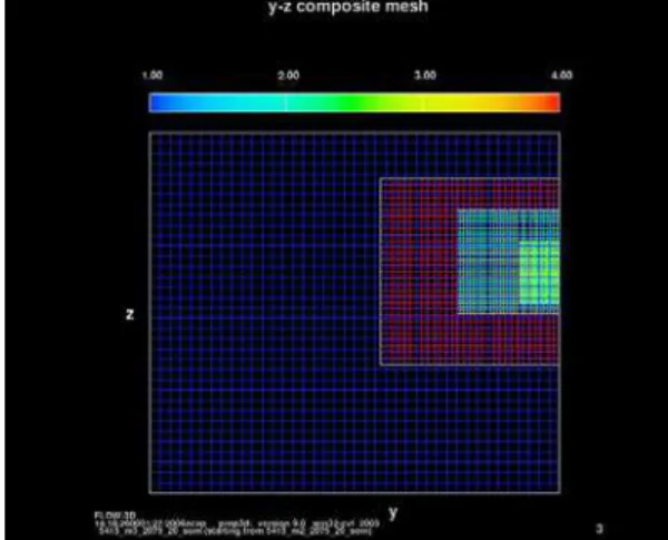
Figure 3: Mesh presentation (1,507,184 mesh elements)
A general background mesh was refined in the area closer to the hull by using multiple mesh blocks and gradually reducing the size of the mesh elements, as shown in Figure 3. For a mesh sensitivity study, three meshes with different mesh refinements were generated (Table 1). Further mesh refinement was not feasible on the original domain size, due to the hardware limitations. Mesh types m4 and m5 were generated by resizing the domain.
Mesh type No. of mesh elements No. of mesh blocks The smallest element size (%L) m1 509,748 3 0.5 m2 1,046,760 3 0.35 m3 1,507,184 4 0.25 m4 1,801,229 4 0.21 m5 2,261,274 5 0.21
Table 1: Mesh characteristics
A physical model is defined as a uniform viscous flow around the hull with specified velocity in the X direction and a hydrostatic pressure field. We deemed that Renormalized group theory (RNG) turbulent model was appropriate for this simulation.
The boundary conditions were as follows: - Specified velocity on inlet;
- Outflow boundary that minimizes wave reflections;
- Hull surface - obstacle with no slip walls; and
- Symmetry plane, side, bottom and top side of domain as free slip walls.
Flow-3D has various numerical options for a solving process. By default, the upwind implicit advection scheme for solving momentum equations is used. The whole resistance curve (a range of Froude numbers flows) has been obtained with the upwind advection scheme, which is robust and fast to resolve. Using the case with Froude number 0.28 and 509,748 element mesh, the advection scheme analysis has been done, comparing the upwind, the second order and the second order with monotonicity preserving advection schemes. The comparison showed superiority of second order advection scheme with monotonicity preserving so this method was adopted as optimal and used for mesh sensitivity study and final resistance prediction.
5. RESULTS AND DISCUSSION
The simulation matrix that has been resolved is presented in Table 2.
No. of mesh refinements
Froude numbers Advection scheme 1(m1) 6 ( 0.17 - 0.4) 1st order 1(m1) 1 (0.28) 2nd order 5(m1 - m5) 1 (0.28) 2nd order with monotonicity preserving 1(m3) 3 (0.21,0.36, 0.4) 2nd order with monotonicity preserving
Table 2: Simulation Matrix
Initially, the numerical prediction of the total resistance has been obtained with a 509,748 element mesh and the upwind advection scheme. The numerical total resistance curve corresponds to experimental curve but is significantly overestimated, for almost factor 3 (see Figure 4). The free surface shape and wave pattern corresponds well to experiments. 0 50 100 150 200 250 300 350 1.0 1.5 2.0 2.5 3.0 3.5 V (m/s) Rt ( N
Flow-3D (upwind) Exp
Figure 4: Total resistance curve (upwind advection scheme, 509,748 mesh elements)
The results obtained with the upwind advection scheme were improved using second order and second order with monotonicity preserving advection schemes, as shown on Figure 5 (for the case Fr=0.28 and mesh type m1). The second order advection scheme with monotonicity preserving is considered to be the optimal, even though calculation time has been prolonged significantly. The numerical
simulations have been run in a serial mode on one PC. The time consumption can be reduced by conducting simulations in parallel mode on multiple PCs or super computer. 140 125 116 44.3 44.3 44.3 0 50 100 150
upwind 2nd order 2nd order with mon.
advection scheme Rt ( N Flow-3D experiments
Figure 5: Advection scheme analysis (509,748 mesh elements, Fr = 0.28)
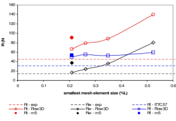
For Froude number Fr = 0.28 a mesh sensitivity study was conducted using second order advection scheme with monotonicity preserving. Mesh types taken into consideration are listed in Table 1. At the point when hardware limitation were reached (mesh type m3), further refinement was possible only with modification of the domain size (mesh types m4 and m5). The change of domain size was done in that manner to minimize impact on the final results, as well as the quality of result comparison. Both meshes have the same size of the smallest element, but different number of mesh blocks and domain size. The change of the wave resistance prediction with the mesh refinement is shown on Figure 6. The initial mesh type m1 was too coarse, causing huge resistance over prediction. In spite the fact that mesh independence has not still be reached, the mesh type m3 already reduced the error significantly. With change in domain size some discontinuity in results appeared.
0 25 50 75
5.0E+05 1.0E+06 1.5E+06 2.0E+06 2.5E+06
no. of mesh elements (-)
Rw
(
N
Exp m 1, m 2, m 3 m 4 m 5
Figure 6: Mesh dependence analysis (Fr = 0.28)
The further mesh sensitivity study was conducted looking into the resistance components separately, as presented on Figure 7. It shows that the frictional component of the resistance reached mesh independence. From mesh type m1 to mesh type m4 the wave resistance, and consequently total resistance, continues to change with mesh refinement. Even though mesh type m4 seems consequent with others, it should be taken with caution due to domain resizing. The mesh type m5 is questionable due to large increment of total number of elements and increment in number of mesh blocks that might be difficult for code to deal with. It can be assumed that for the appropriate mesh with smallest element size 0.21 %L resistance would actually lay between results obtained for mesh type m4 and mesh type m5, suggesting that mesh independence would lay in that region. It would be beneficial to continue with the mesh sensitivity study until the full mesh independence has been reached.
0 20 40 60 80 100 120 140 160 0 0.1 0.2 0.3 0.4 0.5 0.6
smallest mesh element size (%L)
R (
N
Rt - exp Rw - exp Rf - ITTC 57 Rt - Flow3D Rw - Flow3D Rf - Flow3D Rt - m 5 Rw - m 5 Rf - m 5
Figure 7: Mesh sensitivity study (Fr=0.28)
0 50 100 150 200 250 300 350 0.0 0.5 1.0 1.5 2.0 2.5 3.0 3.5 V (m/s) Rt ( N
Flow-3D (upwind) Exp Flow-3D (som)
0 50 100 150 200 250 0.0 0.5 1.0 1.5 2.0 2.5 3.0 3.5 V (m/s) Rw ( N
Flow-3D (upwind) Exp Flow-3D (som)
Figure 9: Wave resistance comparison
Based on the presented analysis final resistance prediction was obtained for mesh type m3, having 1,507,184 mesh elements and second order advection scheme with monotonicity preserving. Initial and final results are presented and compared with experiments and showed in Figure 8 and Figure 9. Significant improvement in the results was achieved. Total resistance prediction error is reduced to around 60% (see Table 3).
Since the analysis of resistance components described above showed that frictional resistance can not be satisfactory predicted with Flow-3D, total resistance obtained by numerical simulation should not be taken in account. A closer correlation of results is obtained using only numerical results for wave resistance and approximating frictional resistance (see Figure 10). ITTC-57 method is commonly used for prediction of the ship frictional resistance in ship’s hydrodynamics[3] and therefore was chosen for this study.
0 20 40 60 80 100 120 140 160 180 200 1.0 1.5 2.0 2.5 3.0 3.5 V (m/s) Rt ( N
Flow-3D Exp Flow3D & ITTC-57 method)
Figure 10: Total results obtained combining Flow-3D and ITTC-57 method
When comparing them with experiments, the total resistance curve is much closer to experimental reducing the error to around 20% (see Table 3). These results were achieved with pre-imposed error introduced by simulating hull on static waterline while model in experiments was free to sink and trim.
Fr (-) ∆Rt(%)- Flow3D ∆Rt (%) Rw(Flow3D) + Rf(ITTC57) 0.21 58.8 12.5 0.28 77.7 23.5 0.36 62.2 23.5 0.41 23.4 7.4
Table 3: Total resistance - Numerical vs. experimental discrepancy (expressed in % of experimental results)
It can be concluded that Flow-3D is suitable for prediction of wave resistance, while prediction of frictional resistance was not successful. It appears that the code does not have the capability to accurately enough resolve boundary layer around the hull and properly predict frictional resistance. This drawback was expected having in mind limitations of the FAVOR method used in Flow-3D for geometry definition. Numerical simulations should still take viscosity into account in the turbulence model so that the flow field and the free surface shape can be properly resolved.
Figure 11: Flow-3D’s and experimental[5] wave pattern comparison (Fr=0.28)
The obtained wave pattern is qualitatively compared with experiments (see Figure 11). The waves are located approximately on the same locations along the hull. A configuration of the mesh blocks is important for obtaining the good wave pattern away from the hull, since the code may smear the significant change in the flow, if appeared on the block boundary as a result of the numerical diffusion between the mesh blocks.
6. CONCLUSION
This numerical study indicated that Flow-3D is an appropriate tool for qualitative analysis of the free surface flow around the ship’s hulls. The upwind advection scheme can be used to properly predict wave pattern. However, for the range of Froude numbers, upwind advection scheme gives total resistance significantly overestimated. The advantage of upwind advection scheme is her robustness and demands less hardware resources and time.
The mesh refinement and multi-blocks schemes improved the results significantly. As a drawback, the calculation time has been significantly increased. This issue might be overcome by increasing hardware resources which would also allow further mesh sensitivity analysis. Different turbulence techniques might give further improvement of the results.
The second order advection scheme with monotonicity preserved is considered as the most suitable for resistance prediction, giving comparative results of 60%. Analyzing the results for frictional resistance it was found that the prediction of frictional resistance was not satisfactory. It appears that the code does not have the capability to accurately enough resolve boundary layer around the hull and properly predict frictional resistance. It can be concluded that Flow-3D is suitable for prediction of wave resistance only. Results obtained for wave resistance combined with frictional resistance calculated using ITTC-57 method gives satisfactory results with error around 20%.
It should be pointed out that a user skill and experience are important in simulation setup, as well as in making proper engineering judgment based on the simulation results of such a complicated problem as the free surface flow around the ship’s hulls.
ACKNOWLEDGEMENTS
We acknowledge with thanks to NRC-CNRC Institute for Ocean Technology in St. John’s, Canada,
and to Professor Don Bass from Memorial University of Newfoundland in St. John’s, Canada.
REFERENCES
[1] Barkhudarov, M., “Multi-Block Gridding
Technique for FLOW-3D", Technical Note
#59-R2, FSI-00-TN59-#59-R2, Flow Science Inc., 2004 [2] Ferziger, H. J., and Peric, M., “Computational
Methods for Fluid Dynamics”, 2001, Springer-Verlag
[3] Lewis, E. V., “Principles of Naval Architecture” SNAME, USA, 1989 [4] Lin, A. C., "Bare Hull Effective Power
Predictions and Bilge Keel Orientation for DDG51 Hull Represented by Model 5415," DTNSRDC/SPD-0200-03, 1982
(http://conan.dt.navy.mil/5415/)
[5] Ratcliffe, T. J., Muntick, I., Rice, J., “Stern Wave Topography and Longitudinal Wave Cuts obtained on Model 5415, With and Without Propulsion”, DTM, USA, 2001
[6] Yao, G. F., “Development of New Pressure-Velocity Solvers in FLOW-3D”, Flow Science, Inc., USA, 2004