https://doi.org/10.4224/20377640
READ THESE TERMS AND CONDITIONS CAREFULLY BEFORE USING THIS WEBSITE. https://nrc-publications.canada.ca/eng/copyright
Vous avez des questions? Nous pouvons vous aider. Pour communiquer directement avec un auteur, consultez la première page de la revue dans laquelle son article a été publié afin de trouver ses coordonnées. Si vous n’arrivez pas à les repérer, communiquez avec nous à [email protected].
Questions? Contact the NRC Publications Archive team at
[email protected]. If you wish to email the authors directly, please see the first page of the publication for their contact information.
NRC Publications Archive
Archives des publications du CNRC
For the publisher’s version, please access the DOI link below./ Pour consulter la version de l’éditeur, utilisez le lien DOI ci-dessous.
Access and use of this website and the material on it are subject to the Terms and Conditions set forth at Task 2: Literature Review: Building Envelope, Heating, and Ventilating Practices and Technologies for Extreme Climates
Said, M. N.
https://publications-cnrc.canada.ca/fra/droits
L’accès à ce site Web et l’utilisation de son contenu sont assujettis aux conditions présentées dans le site LISEZ CES CONDITIONS ATTENTIVEMENT AVANT D’UTILISER CE SITE WEB.
NRC Publications Record / Notice d'Archives des publications de CNRC:
https://nrc-publications.canada.ca/eng/view/object/?id=495b2601-5911-45bc-9067-62441513ba6d https://publications-cnrc.canada.ca/fra/voir/objet/?id=495b2601-5911-45bc-9067-62441513ba6d
http://irc.nrc-cnrc.gc.ca
Ta sk 2 : Lit e ra t ure Revie w : Building Enve lope , H e a t ing, a nd
Ve nt ila t ing Pra c t ic e s a nd Te chnologie s for Ex t re m e
Clim a t e s
B - 1 2 3 9 . 2
M . N . A . S a ï d
D e c e m b e r 2 0 0 6
PERD-079 -
Engineered Building Envelope Systems to Accommodate
High Performance Insulation with Outdoor/Indoor Climate Extremes
Task 2: Literature Review
Building Envelope, Heating, and Ventilating Practices and Technologies
for Extreme Climates
M. N. A. Saïd, Ph.D., P.Eng.
Institute for Research in Construction National Research Council Canada
Ottawa, Ontario, Canada
DISCLAIMER
This report presents a review of literature. The views reported are those expressed in the original documents and do not necessarily reflect the views of the Institute of Research in Construction of the National Research Council Canada.
Table of Contents
List of Figures and Tables... v
List of Acronyms ... vi
Executive Summary
... viii1. Introduction
... 1Background ...1
Materials: Temperature and Moisture Effects...2
Moisture Control: Northern Regions ...5
Moisture Control: Coastal Regions...10
2. Building Envelope Technologies
... 12Canadian Technology ...12
Advanced Framing Technology... 12
Upgraded Thermal & Air Tightness Wall Systems... 13
Best Practices in Wood Frame Envelopes... 18
Building Envelopes: Northern Canada ...21
Building Envelope Examples, Northern Canada... 22
Energy Efficient Houses, Northern Canada... 28
Design Considerations and Strategies... 29
Foundation Design Considerations... 34
Roof Design Considerations... 38
Building Envelopes: Humid Climates...41
Indigenous Architecture...42
Arctic Indigenous Architecture... 43
Maritime Climate Indigenous Architecture... 45
Sustainability Concepts in Indigenous Architecture... 46
Global Practices in Building Envelopes...47
Arctic and Antarctic Regions... 47
Scandinavian Region... 57
Japan... 59
Zero-Energy Sustainable Houses ...60
The Eagle Lake Healthy House... 60
The Saskatoon Super-Insulated House... 62
The Alberta Sustainable Home... 64
The Passivhaus - Europe... 66
The Hanover House... 67
The Klingenberg House... 70
Innovative Wall Assemblies ...74
Cold Climate... 74
3. Heating, Ventilation, and Energy Technologies
... 79Heating and Ventilating ...79
HVAC Design Considerations... 79
Ventilation: Design Considerations... 80
District Heating Considerations... 83
Indoor Air Quality and Health ...83
Mould... 83
The Eagle Lake Healthy House... 84
Indoor Air Quality: Northwest Territories Housing... 84
Energy ...85
4. Socio-Economic Issues
... 87The Vegetation Ecosystem...87
The People ...88
5. Conclusion
... 90Appendix A: Literature Search Approach
... 97References
... 99List of Figures and Tables
Figures
Figure 1. Assemblies of Prefabricated Walls: 1995 Practice and Proposed Walls by Burch et al.
(Source: Burch et al. 1995, Figures 1 and 5)... 9
Figure 2. Thermally Upgraded Single Stud Wall... 14
Figure 3. Double Stud Walls Assembly... 16
Figure 4. Standoff Wall System... 17
Figure 5. Ceiling Assembly, Nunavik, Quebec... 23
Figure 6. Wall Assembly, Nunavik, Quebec... 24
Figure 7. Floor Assembly, Nunavik, Quebec... 24
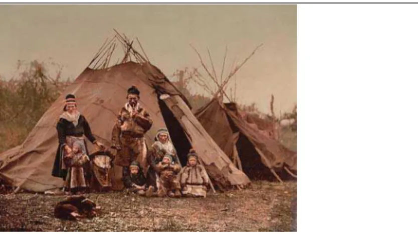
Figure 8. A Sami Family and Hut around 1900... 44
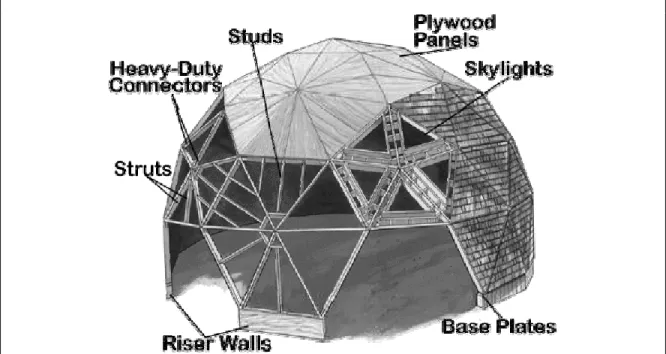
Figure 9. An Example of a Dome Building and Anatomy... 48
Figure 10. Wall Assembly of the Finnish Energy-Efficient House... 58
Tables Table 1. Assemblies of Prefabricated Walls: 1995 Practice and Proposed Walls by Burch et al... 8
Table 2. Rated and Whole-Wall RSI (R) Values of SIP and Wood Frame Walls... 28
Table 3. R-Values, Finnish Building Code for Detached Houses ... 58
Table 4. Range of R-Values of Insulation Used in Houses in Japan’s Cold Regions ... 60
Table 5. Passive House Standard for Low-Energy Houses for the Central Europe Climate ... 66
Table 6. The Hanover House, Measured Annual Energy Performance during the Heating Season ... 69
Table 7. Specifications of the Klingenberg House ... 70
Table 8. Comparison of R-Values and Air Tightness of Four Super-Insulated Building Envelopes... 73
Table 9. U-Values for Windows and Walls with Capillary Transparent Insulation Materials ... 75
Table 10. Target R-Values for Low-Energy Houses in Finland ... 85
Table 11. Example RSI (R) Values of Building Envelopes, Northern Canada ... 91
List of Acronyms
ach Air changes per hour
ACHP Alaska Craftsman Home Program
ASHRAE American Society of Heating, Refrigeration and Air-Conditioning Engineers CFCs Chlorofluorocarbons
cfm Cubic feet per minute
CHBA Canadian Home Builders’ Association
CMHC Canada Mortgage and Housing Corporation
EBN Environmental Building News
EDU Energy Design Update
EIFS Exterior Insulated and Finish System
EPDM Ethylene propylene diene monomer
EPS Expanded polystyrene
fpm Feet per minute
HCFCs Hydrochloro-fluorocarbons
HDD Heating degree day
HRV Heat recovery ventilator
HUD US Department of Housing and Urban Development
HVAC Heating, ventilation, and air conditioning
IAQ Indoor air quality
ICF Insulating concrete form
L/s Litres per second
MDO Medium density overlaid plywood
m/s Metres per second
NoRTH Northern Research and Technology
NRC National Research Council
NWT Northwest Territories
OSB Oriented strand board
ppm Parts per million
PVC Polyvinyl chloride
SIP Structural insulated panel
VDP Vapour diffusion ports
Executive Summary
Canada’s regions north of 60 degrees of latitude occupy over 70% of the nation’s area, but are populated by less than 1% of the nation’s population. Housing designs in Northern Canada are imported from southern regions. As a result, building durability is poor, which affects the quality of the built environment and energy budgets as well as the global environment. The Heat and Moisture Performance of Envelopes group of the Building Envelope and Structure program of the National Research Council of Canada, has started a four-year project to develop durable, energy-efficient wall assemblies that can accommodate the challenges of environmental conditions in Northern Canada as well as along northern coastal regions.
The main objective of Task 2 of the project is to provide a knowledge base for selecting building envelope assemblies to investigate in the analysis tasks of the project. This includes conducting a global literature search to identify technologies, practices, and issues for buildings subjected to extreme environmental conditions. This report
documents the findings of the literature review, which includes significant information on practices, issues, and technologies regarding building envelopes, construction, heating, ventilating, indoor air quality, utilities, and socio-housing issues. The literature review also includes example building constructions from the arctic, Antarctica, Scandinavia, the Himalayan region, Japan, as well as indigenous architectures’ climate adaptation.
Climate Outdoors
Climate in the arctic and sub-arctic regions varies considerably, particularly, above and below the tree-line regions. Variations include the snow drifting pattern, wind,
temperatures, annual amounts of sunshine, and daylight. For example, in the NWT, temperatures range from -45ºC (-49ºF) in winter to 35ºC (95ºF) in summer. Precipitation is mainly in the form of snow with an annual range from 140 mm (5 ½ in.) in Hay River to 425 mm (16 ¾ in.) in Inuvik. High winds and blizzards are common. Daylight, in particular, is extremely variable. It ranges from almost 24 hours of daylight daily in summer with the sun setting just before midnight and rising a few hours later, to very little daylight in winter. In Alaska, low temperatures can range from -57ºC (-70ºF) for weeks in interior areas to -34ºC (-30ºF) in south central and western areas and last for extended periods. Wind speeds in excess of 200 km/h (125 mph) are common. The maritime climate, dominated by ocean influences, is humid and temperate. Precipitation occurs in all seasons, and might change by the hour. The weather could come from any orientation. Summers are cool and short. Winters are mild and short with some frost but not continuous snow. Spring and fall are extended in length. There are small differences between monthly mean temperatures.
Climate Indoors
As an example, indoor air temperatures in NWT homes averaged from 21ºC to 28ºC (70ºF to 82ºF), RH ranged from 9% to 46%, with an average of 25%, and air change rates varied from 0.042 ach to 2.2 ach. A 20% RH indoors is considered optimum during an
arctic winter. Occupants’ discomfort might increase at a RH less than 20%. RH above 20% could lead to condensation.
Selecting Building Envelope Assemblies for Northern Canada
Criteria are based on the following challenges for building construction in Northern Canada.
• Harsh environmental conditions: Prevalent low temperatures, wind, and snow drifting conditions exist during the long winters. This leads to large temperature differentials between indoors and outdoors. Extremely variable daylight conditions range from a few hours a day in winter to constant bright sunshine in summer. Snow drifting patterns, winds, temperatures, and the annual amount of sunshine vary throughout the region.
• Lifestyle: The North features a wide range of cultures and lifestyles, some of which can generate considerable moisture indoors.
• A short construction season: Measured in weeks, the season is characterized by high transportation costs and difficulties due to the landscape and remoteness of the region. The availability of skilled labour and equipment, and the high energy costs are also problems.
Current Wall Systems - Northern Canada
Wood frame systems are common in Northern Canada. These systems use 38 x 139 mm (nominal 2 x 6) timber framing; mineral wool or fibreglass batt insulation in stud spaces; air, vapour, and weather barriers; and plywood or oriented strand board (OSB) sheathing. Semi-rigid insulation might be used over vertical strapping. Galvanized steel siding is common. In some regions, structural panel siding of engineered wood strands replaces sheathing and is nailed directly to the studs. Structural insulated panel systems (SIPs) have also performed well in northern Canada.
Specific design strategies are required for each locale in Northern Canada, because of the variation in environmental conditions. Foundations and envelopes that are wind and snowdrift resistant are design essentials north of 60 degrees. Buildings incorporate expansion joints to compensate for structural movement due to large temperature
variations from winter to summer. Walls, floors, and ceilings are insulated and windows are triple-glazed sealed units with low-e coating and insulated preferred frames are PVC, vinyl, or fibre reinforced plastic.
Roof
Avoid stepped roofs, offsets, nooks, or parapet walls to prevent accumulation of snowdrifts. Use a sloping roof section to connect two roof levels. Metal roofing has performed satisfactorily. Skylights are not recommended unless they are designed to control condensation. Preferred minimal eave projections range from 200 to 600 mm (8
to 24 in.) in areas below the tree line and from 100 to 200 mm (4 to 8 in.) in areas above the tree line. Below the tree line, ventilated roof systems perform well. Above the tree line, roof venting is problematic. It is difficult to avoid snow infiltration through vents. Incorporate drains for melted snow.
Foundations
Incorporate strategies to minimize the impact of the building on the thermal equilibrium of the permafrost and reduce snowdrift accumulation. A common strategy is elevating the building about 0.9 to 1.2 m (3 to 4 ft.) above the ground. A Swedish study concluded that a 1.8 m (6 ft.) elevation worked well in Antarctica.
Daylight Extremes
In winter, harness any daylight available through large windows, clerestory windows, and strategically placed skylights. In summer, latticed window screens are used to block the sun’s rays. Window shading devices are optimized using solar angle calculations, to block excessive daylight and solar heat gain of the summer high sun and maximize the entry of the low winter sun.
Construction
Considerations are given to the availability of labour and equipment as well as the speed of construction.
Wall Systems to Consider
Northern regions: General considerations for building envelope assemblies include super-insulated (based on a target annual energy budget according to the regions’ climate and challenges), airtight, and breathable assembly. The availability of material,
construction equipment, and labour as well as construction methods that encourage local participation are additional considerations.
• Double stud walls consist of a load-bearing wall and a lighter non-load bearing wall supporting exterior siding or interior drywall. Additional insulation is added in the space between the two walls. Wall thickness depends on the insulation level to be determined with energy optimization analysis based on a target energy budget.
Variations in the double stud walls approach include the double 38 x 89 mm (nominal 2 x 4) stud walls system and standoff walls in which one wall is constructed with truss studs designed to accommodate the required insulation. The wall placement is offset relative to the interior stud wall (38 x 64 or 38 x 89 mm / 2 x 3 or 2 x 4 framing) to cover the edge of the floor slab to minimize its thermal bridging. • Structural insulated panels are factory manufactured with a polystyrene,
polyurethane, or glass fibre insulating core sandwiched between wood panel sheathing, waferboard, or drywall. May include stiffeners for more panel rigidity. Panels could be installed over timber frame of wall or roof systems as sheathing. • Concrete wall systems use insulating concrete forms that provide the formwork for
Coastal northern regions: For the high-moisture climate in coastal northern regions, key criteria for building envelope assemblies include the ability to handle as well as withstand wetting spells with little impact on the assembly durability. Examples include thermally upgraded rain screen systems consisting of a 38 x 139 mm (2 x 6) stud wall with blown-in blown-insulation blown-in the stud spaces, exterior breathable blown-insulatblown-ing sheathblown-ing board, a vented air space, and cladding.
Concepts to consider from:
• The advanced wood framing technology: To conserve timber materials, use 38 x 89 mm (2 x 4) lumber for cripples and jack studs, 38 x 89 mm (2 x 4) lumber for the bottom and top plates, and drywall clips at the corners to eliminate three-stud corners. • Indigenous adaptation principles:
o Wind-shedding characteristics of the dome architectural form of the igloo reduce erosion of envelope surfaces, accumulation of snowdrifts, and heat loss.
o Damp maritime climate conditions: Use masonry walls or stucco over earthen or adobe walls. For wood, apply protective paint. In northern coastal areas, use large windows to harvest daylight to compensate for overcast skies. Incorporate windows in all directions to provide daylight and summer ventilation. Use window shutters or storm windows to protect against storms and winter cold. o Integrate heating and cooling comfort appliances with building design.
• Passive house standards:
o Determine the wall insulation level, hence the wall thickness, based on an energy optimization analysis for a target energy budget. As a guide, the European
passivhaus construction guidelines specify heating energy budgets in the range 10 to 20 kWh/m² for Central Europe.
Comparison of RSI (R) for Super-Insulated Building Envelopes and Current Practice in Northern Canada
Super-Insulated Envelopes Northern Canada Current Practice
Walls 7.0 to 10.6 (40 to 60) 5.0 (28) Roof 10.6 to 14.1 (60 to 80) 7.0 to 7.7 (40 to 44) Floor 5.3 to 10.6 (30 to 60) 5.4 to 9 (31 to 51)
o Use a two-layer insulation approach to reduce thermal bridging. o Use two layers of drywall in the interior face of walls for storing heat.
o Avoid penetrating the building envelope to reduce energy losses as well as not to weaken moisture control barriers. Avoid installing electric boxes or wiring in the exterior walls. For outdoor lights, use wireless battery-operated fixtures in shallow surface-mounted boxes.
1. Introduction
Background
Canada’s regions north of 60 degrees of latitude occupy over 70% of the nation’s area, but is home to less than 1% of the nation’s population. Attention has focused on energy efficiency in northern housing designs, with little attention to the suitability of the house to the northern life style. In his textbook introduction, Strub (1996) pointed out that poor building durability in the arctic and antarctic regions is due to the lack of home-grown design and the local construction industry. Polar regions imported copies of building designs from the mid-latitude regions (40 to 60 degrees of latitude). Imported designs solved some problems but created others. When buildings do not fit the need of the occupants, they are poorly cared for and the buildings’ service life is shortened
considerably. Some buildings lost their service life in the first five years with moisture as the prime factor. Poor durability of building envelopes affects the quality of the indoor environment and the buildings’ energy budget which, in turn, has a negative impact on the global environment.
Several challenges face building construction in the north of 60 regions.
• Harsh environmental conditions: Low temperatures, wind, and snow drifting prevail during long winters. Large temperature differentials occur between indoors and outdoors. Extremely variable daylight conditions range from a few hours a day in winter to constant bright sunshine in summer. Snow drifting patterns, wind,
temperatures, and annual amounts of sunshine vary throughout the region.
• Lifestyle: The North features a wide range of cultures and lifestyles, some of which can generate considerable moisture indoors.
• Building construction season: Measured in weeks, the season is characterized by high costs of energy and transporting building materials due to the landscape and remoteness of the region. The availability of skilled labour and equipment is a problem.
The Heat and Moisture Performance of Envelopes group of the Building Envelope and Structure program, of the National Research Council (NRC), has started a four-year research project to develop durable, energy-efficient wall assemblies that can
accommodate the challenges of environmental conditions in Canada’s northern regions as well as northern coastal regions. The main objective of Task 2 of the project is to provide a knowledge base for selecting building envelope assemblies to investigate in the analysis tasks. The approach of Task 2 includes conducting a global literature search to identify technologies, practices, and issues for buildings subjected to extreme environmental conditions.
The literature search resulted in over 100 documents. This report identifies the finding of the literature review, which includes significant information on practices, issues, and technologies regarding building envelopes, construction, heating, ventilating, indoor air quality, utilities, and socio-housing issues. The literature review also includes examples of building construction from the arctic, Antarctica, Scandinavia, the Himalayan region of India, Japan, as well as indigenous architectures’ climate adaptation. The report is organized according to building envelope technologies; heating, ventilation, and energy technologies; and socio-economic issues.
Materials: Temperature and Moisture Effects
Moisture issues range from some surface condensation on windows to severe cases that result in decay of the structure. Between these extremes, moisture issues could manifest as stains, peeling paint, leaks, or mould growth on the interior finish. Hutcheon (1960), Wilson (1960), and Hansen (1984) emphasized that winter condensation is probably the most common moisture-related problem affecting houses in Canada. Hutcheon explained that low outdoor temperatures in winter give rise to condensation on and in walls and windows, and tend to produce low relative humidity indoors. Even moderate humidity inside buildings can produce wetting by condensation on and in the building envelope components, because of the large temperature gradients within the building envelope in a Canadian winter.
Hutcheon and Handegord (1989) discussed the effect of temperature on building materials. The influence of temperature on building materials depends on the rate of change in temperature, material properties, and the material’s moisture content. For dry homogeneous building materials, slow changes in temperature have little effect. Rapid temperature changes resulting in internal temperature gradients could produce stresses and strains, because of thermal expansion and contraction and, in extreme cases, could lead to fracture of the material if it is restrained. The breakage of window glass due to cooling at the edges is an example of this case. Plastic materials, however, do not fail when restrained, because they have low moduli of elasticity.
For porous materials, the degree of moisture saturation at the time of freezing is a critical factor. Freeze–thaw cycling combined with high moisture levels greatly increases the risk of frost damage to porous materials, such as masonry. For example, the risk of frost damage is high when the masonry moisture content is more than 75% by pore volume. The risk of frost damage also depends on the rate of freezing and on the pore structure of the material. Rapid freezing that does not allow for moisture redistribution within the material could lead to crack development and spalling.
Corrosion, a chemical reaction, of metal materials also depends on the temperature. In the cold climate, the influence of temperature is in producing wetting conditions. Corrosion of metals depends on the length of time the material is exposed to high humidity over 80%. Corrosion could take place at a lower humidity if salt is present.
Moisture Issues: Wood Frame Construction
Canada Mortgage and Housing Corporation (1993) summarized moisture issues in Canadian wood frame house construction from 1975 to 1991.
• Construction practices in Canada’s southern regions may lead to serious moisture problems when used in Canada’s northern and coastal regions.
• High indoor humidity usually characterizes moisture-troubled houses.
• High indoor humidity is usually a result of a reduction in natural ventilation rates when flues are reduced or eliminated.
• Certain insulation practices that involve low permeability insulation sheathing can reduce the drying potential of wood frame walls.
• Material properties and the moisture-driving forces and transport mechanisms in wood frame walls are complex making it difficult to assess.
Canada Mortgage and Housing Corporation (CMHC, 1993) also summarized research needed for unresolved moisture issues in wood frame construction in Atlantic Canada. Research is needed to identify improvements to current practices for the application of low permeance insulating sheathing, and an examination of current sheathing system practices with regard to preventing air leakage into and out of insulation systems. Moisture Issues in Northern Alberta
The Alberta Housing Division investigated the cause and solution strategies for condensation problems in rural northern Alberta homes (Lee, 1991). Many houses affected by moisture damage were built in the early 1980s. Condensation damage ranged from stains and mould growth, to deterioration of the building envelope. Some of the moisture-damaged homes were selected for monitoring of indoor temperature and humidity over the heating season of 1988-1989.
Moisture Condensation Causes
A combination of factors led to excessive condensation on wall surfaces and within the building envelope, which caused surface damage, rot, mould growth, and general building decay. There were several contributing factors.
• Lifestyle of occupants: This is the largest source of moisture (game preparation, boiling-based cooking style, washing and hanging clothes to dry, firewood storage, etc.). Moisture is often brought into the house by tracking in snow and water. An enclosed porch at the house entrance helps minimize this factor.
• Building construction: Southern home designs were adopted in the north without alteration. This resulted in a poorly insulated building envelope. Condensation occurred in the attic space, because of indoor air leaking through the attic hatch. • Heating and ventilation: Wood-burning appliances are the most common. Heat
distribution from such appliances is limited to the appliance location as it relies on radiation and natural convection currents to disperse. Also, the operation of the wood
stove is usually intermittent to conserve timber. Limited air circulation caused high humidity in bedrooms, bathrooms, and the kitchen particularly in room corners.
Moisture Mitigation Strategies
Criteria for the selection of mitigation strategies included those that did not require a lifestyle change of occupants, were relatively maintenance free, and economical. The following three mitigation strategies were installed and monitored. The three strategies lowered indoor humidity, but with various operation concerns.
• Increase outdoor air intake of forced air furnaces: In this strategy, furnace
modifications to increase the outdoor air intake compromised the performance of the furnace.
• Increase the stack effect induced air pressures for wood stove heated homes: This strategy was too inconsistent, because of the effect of uncontrolled factors, such as wind and outdoor temperature conditions.
• Install a make-up air unit with preheat and a variable flow rate, which supplies
air directly to the living area: This strategy (after working out some operation problems — noise, insufficient preheating capacity, and inadequate airflow rates) was found to be the most effective method to reduce indoor humidity and minimize condensation and resultant building envelope damage. The make-up air also improved indoor air quality and safeguarded against chimney back drafts. For a household of nine occupants, the cost of operation (fan and electric preheat) in 1991 was $15 per month.
Moisture Conditions in Buildings in Fairbanks, Alaska
Adkins (1996) discussed moisture conditions and the difficulties in controlling indoor relative humidity (RH) within recommended standards in the range of 25% to 60% in residential and commercial buildings in Fairbanks, Alaska. Difficulties included the dryness of ventilation air especially after cold outdoor air is heated to room temperatures and the poor design and construction of the vapour and thermal control of building envelopes. Standards requirements vary.
• American Society of Heating, Refrigeration and Air-Conditioning Engineers
(ASHRAE) standards: 7 litres/second (L/s) (15 cubic feet/minute or cfm) per person.
• The Uniform Building Code for Dwellings: 7 L/s (15 cfm) per person, 2 air changes per hour (ach), or operable windows with openings of not less than 1/10 of floor area. • Alaska Craftsman Home Program (ACHP) ventilation standard: 1/3 ach.
Adkins presented RH samples in buildings in and near Fairbanks. In residential buildings, humidity levels were much higher and mould problems more frequent than in commercial buildings. Average RH in 31 residential buildings was 37.4% and the range was 19% to 60%. The houses with RH in the range 19% to about 30% did not have condensation or mould problems: houses with RH of 36% to 60% had severe problems. In 23 commercial buildings, average RH was 13.5% and the range was 6% to 29% except in the University
of Alaska museum where RH was 45%. Adkins suggested 30% RH in buildings in Fairbanks was reasonable and achievable in residential buildings. In commercial buildings, 30% RH could be achieved by separating the construction process of the vapour and insulation from interference by the structure, electrical, mechanical, and finish materials.
Moisture Control: Northern Regions
Three types of barriers are needed in building envelopes in the north (CMHC, 1994-1): • a wind or weather barrier on the outside of the envelope to protect the envelope from
blowing snow and rain;
• an air barrier system to prevent exfiltration of indoor air through the envelope; and • a vapour barrier, on the warm side of the envelope, to prevent water vapour from
entering the envelope.
One material may serve as an air and vapour barrier provided it is located on the warm side of the envelope.
Impact of Improper Selection and Placement of the Vapour Barrier, Arctic
Carlson (1996) demonstrated how improper selection and placement of the insulation, the vapour barrier, and the lack of venting of wall assemblies could lead to building envelope deterioration due to condensation that usually becomes apparent five to ten years later. Moisture diffusion through the inner layer of the building envelope might condense near impermeable outer layers and freeze as the temperature drops below the dew point and freezing. Moisture accumulation and frost buildup will be much greater in northern climates, such as Alaska and Minnesota.
The examples included a retrofit of an impermeable exterior insulated and finish system (EIFS), which was applied on the exterior of an insulated wall in a building in Fairbanks, Alaska. A polyethylene vapour barrier was placed on the warm side next to the interior gypsum board, but because of imperfections, water vapour diffused into the wall, condensed, and froze near the inner face of the EIFS panel. As a result, the panel’s fasteners corroded and the frost buildup caused some panels to protrude from the wall. Carlson attributed this damage to a lack of venting of the EIFS panels. Venting would allow excess moisture to drain or evaporate.
Carlson (1996) also presented a spreadsheet tool to assist designers and builders in the selection and placement of the vapour barrier, insulation, and venting in the building envelope assembly. The spreadsheet calculates dew point temperatures in insulated building envelope assemblies. As an example, Carlson used the spreadsheet to investigate moisture deterioration of a Fairbanks, Alaska, building. Carlson made the following recommendations.
• A dew point analysis should be conducted for each building envelope assembly based on local climate conditions. The calculations are particularly important for EIFS and other insulated assemblies retrofitted over insulated steel or wood framing.
• Thermal and vapour properties of building materials should be placed side by side in the same table.
• Insulated impervious building envelope assemblies should include adequate drainage and venting to foster evaporation and drainage of condensate should it occur.
Are Vapour Barriers Necessary in Norway?
Thue et al. (1996) discussed whether a vapour barrier is necessary for wood frame walls and ceilings in cold climate regions. Noting that the function of the vapour barrier is to minimize the diffusion of indoor water vapour into the wall/ceiling assembly (or outdoor water vapour in hot humid climate regions), some believe the so-called “breathing constructions” (i.e., wall assemblies with vapour-permeable components) have as good a moisture performance and contribute to better indoor air quality.Thue et al. argued that there are no general design recommendations regarding the requirements for vapour barriers in wood frame construction. For example, what limits of water vapour resistance are recommended for barriers on the cold and the warm sides of the insulation?
Norwegian houses without a vapour barrier did not suffer moisture damage when the wall assembly was airtight [Comment: this is probably because the wall finish, e.g., a painted gypsum board performed the function of the vapour barrier, and indoor air leakage was minimized by the airtight assembly.] In Norway, a typical wood frame wall assembly consists of (inside to outside) the gypsum board or wood paneling wall finish; 0.15 mm (6 mil) poly vapour barrier or equivalent, placed on the warm side of insulation; 150 mm minimum thermal insulation (rock wool, glass wool, or loose fill cellulose fibres) in the stud space; a wind barrier (building paper, fibreboard, or gypsum board), and the
ventilated exterior wood paneling. (Thue et al. noted that plywood sheathing, commonly used in North America, is not used in Norway.)
Because of the limited results of only two laboratory tests, Thue et al. (1996) could not provide a firm answer to the question of whether a vapour barrier is necessary for wood frame walls and ceilings in cold climate regions. The authors made the following conclusions.
• A wood frame building envelope with a 0.15 mm (6 mil) polyethylene vapour barrier on the warm side of the insulation could be considered “moisture safe” if it has no air leakage.
• The tests indicated that two parameters have to be considered in wood frame
construction in cold climates: the vapour diffusion resistance (or vapour permeability) at the warm side of the insulation, and the ratio between vapour diffusion resistances at warm and cold sides (the vapour resistance ratio).
The values of these two parameters depend on the thermal resistance of the wall. Higher insulation levels would emphasize the requirements for a vapour barrier as potential condensation increases in the wall as the temperature decreases in the components on the cold side of the wall. A high vapour resistance ratio might compensate for a low vapour diffusion resistance on the warm side. Thue et al. presented the following design rules, but with caution because of the limited results.
Let Zw is warm side vapour resistance, and Zc is cold side vapour resistance
Zw < 7500 m2 h Pa/g use Zw/Zc > 50
7500 < Zw < 10 000 m2 h Pa/g use Zw/Zc > 25 Zw > 10 000 m2 h Pa/g use Zw/Zc > 10 No Vapour Barrier Case: Sweden
Levin and Gudmundsson (2000) conducted in situ measurements of the moisture content and temperature in walls, roofs, and floors in three houses in which the vapour barrier was replaced by more diffusive open materials. The objective of the measurements was to evaluate how this vapour barrier replacement might affect the risk of condensation in the building envelope. Their study was motivated by a tendency to replace the traditional polyethylene vapour barrier with more diffusive open materials, such as polypropylene fabric, due to a concern for the environment. The measurements were taken at the outermost part of the insulation layer of the building envelope assembly, every three weeks over a two-year period. Indoor temperature and relative humidity were continuously monitored. The in situ measurements were used to develop a one-dimensional transient moisture diffusion computation model to predict the moisture performance of building envelopes for various indoor moisture loads.
Measurements indicated that, for low indoor moisture loads, there was no immediate risk of moisture damage. Computations with indoor moisture loads of 2 and 4 g-vapour/m3-air and the climate of Stockholm, Sweden, showed that moisture would condense in the wall assembly [see note in the box]. Also the risk of mould growth in the building envelope was feasible, because of prolonged periods of high relative humidity conditions that coincided with favourable mould growth temperatures. Similar computations of the pile-type
foundation system showed that the risk for condensation is also high for moderate indoor moisture loads.
Levin and Gudmundsson concluded that the building envelope construction that replaces the traditional polyethylene vapour barrier with more diffusive materials, such as
polypropylene fabric, is not recommended.
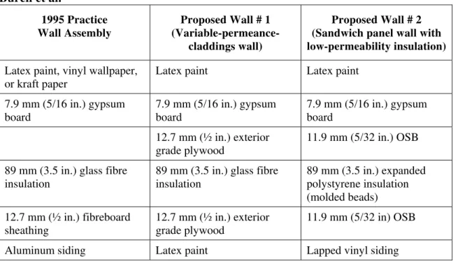
Wall with Satisfactory Moisture Performance for All Climates in United States Burch et al. (1995) computed moisture performance of a wall assembly using 1995 construction practices in prefabricated housing, and two proposed alternative wall designs (Figure 1) for both hot and humid, and cold climates. They used a
one-[Comment: The following table puts in perspective the moisture load values, 2 and 4 gv/m3 dry air, used by the authors. The values
correspond to a quite dry environment indoors (10% RH at 22ºC/72ºF and 20% RH at 24ºC/75ºF).] T (ºC) RH (%) w (gv/m3air) 24 50 11.4 30 6.5 20 4.4 22 10 1.9 Where w is humidity ratio gv/m3 dry air
dimensional computer model (MOIST), which could only provide approximate average moisture performance for actual three-dimensional physical conditions. The authors noted that, during winter, more moisture might accumulate in the walls of prefabricated houses than those built on site, because they are fabricated tighter and thus have lower air infiltration rates and thus lower potential drying out of the wall. Table 1 compares the assemblies of prefabricated walls and the proposed walls.
Table 1. Assemblies of Prefabricated Walls: 1995 Practice and Proposed Walls by Burch et al. 1995 Practice Wall Assembly Proposed Wall # 1 (Variable-permeance-claddings wall) Proposed Wall # 2 (Sandwich panel wall with low-permeability insulation)
Latex paint, vinyl wallpaper, or kraft paper
Latex paint Latex paint
7.9 mm (5/16 in.) gypsum board 7.9 mm (5/16 in.) gypsum board 7.9 mm (5/16 in.) gypsum board 12.7 mm (½ in.) exterior grade plywood 11.9 mm (5/32 in.) OSB
89 mm (3.5 in.) glass fibre insulation
89 mm (3.5 in.) glass fibre insulation 89 mm (3.5 in.) expanded polystyrene insulation (molded beads) 12.7 mm (½ in.) fibreboard sheathing 12.7 mm (½ in.) exterior grade plywood 11.9 mm (5/32 in) OSB
Aluminum siding Latex paint Lapped vinyl siding
Vapour Retarder Requirement
The 1993 Manufactured Home Construction and Safety Standards from the US
Department of Housing and Urban Development (HUD) include the following moisture control practice rules for prefabricated homes.
1. Install an interior vapour retarder with a permeance of 57 ng/s m2 Pa (1 perm) or less, or
2. use permeable sheathing and siding that has a combined permeance higher than 290 ng/s m2 Pa (5 perm), or
3. provide an outdoor ventilated cavity between the siding and wall insulation.
An interior vapour retarder is not required in prefabricated homes when one of the first two options is used. Burch et al. (1995) decided not to consider the third moisture control option, because literature showed that a ventilated cavity might provide poor moisture performance in both hot and humid, and cold climates. The authors considered the combined permeance of the fibreboard sheathing and the aluminum siding to be considerably greater than the 5 perm required by option 2 of the HUD standards.
c) Proposed Wall # 2
b) Proposed Wall # 1
a) 1995 Current Practice
Figure 1. Assemblies of Prefabricated Walls: 1995 Practice and Proposed Walls by Burch et al. (Source: Burch et al. 1995, Figures 1 and 5).
Burch et al. (1995) called Wall # 1 the “variable-permeance-claddings wall,” because the moisture behaviour of the plywood varies with ambient relative humidity. When the relative humidity is below 50%, the plywood behaves as a vapour retarder. When the moisture content of the plywood approaches saturation, it becomes very permeable. Computations showed that, for Madison, Wisconsin, a manufactured wall assembly, built to 1995 standards without an interior vapour retarder and permeable sheathing, may not provide satisfactory moisture performance in a cold climate. The same wall but with an interior vapour retarder (vinyl wallpaper, latex paint, or kraft paper) showed acceptable performance in a cold climate such as in Madison, but as expected, performed poorly in a hot and humid climate, such as in Miami, Florida. The proposed wall assemblies with the “variable-permeance-claddings wall” and “sandwich panel wall with low-permeability insulation” both exhibited satisfactory moisture performance in both the cold and the hot and humid climates, even with moderately severe indoor conditions. The proposed walls also performed satisfactorily in a mixed climate, such as in Little Rock, Arkansas. Burch et al. concluded that the proposed wall assemblies would provide satisfactory moisture performance in all climatic regions of the United States.
Moisture Control: Coastal Regions
In coastal regions, deflecting or shedding rainwater off the façade is the first line of defence against rainwater entry into building envelopes. As a second defence, draining wet spells back to the outdoors reduces the length of time a material is exposed to water and thus lessens potential damage to the wall.As a secondary barrier, a weather barrier is used to block rainwater entry into the inner wall assembly while allowing for
breathability of the wall to facilitate drying. Weather Barrier
Canada Mortgage and Housing Corporation (2004) summarized a study that examined the effect of various factors on the performance of various weather barrier materials. These factors included the type of substrate, outdoor weathering, various extractives and surfactants, and fastener penetration. The study concluded that the weather barrier performed well when the wall assembly included a drainage cavity between the weather barrier and the cladding. The drainage cavity prevents water contact to the weather barrier on both sides, because when this occurred water was observed to travel through the weather barrier. [Comment: probably by the capillary action.] Aging, weathering, or mechanical stretching did not affect the weather barrier’s pore size. The barrier did not function under some combination of weathering in the presence of wood extracts and other solutes as significant water was observed to pass through the weather barrier. Drying the Wall Assembly
Joy et al. (1948) observed that ventilation of a wall cavity was effective in controlling condensation in certain cases, particularly when air movement in the cavity was not impeded. The use of vapour diffusion ports (VDPs) is a drying strategy that has been used in the lower mainland of British Columbia (CMHC, 2002-1). The concept involves creating one or two holes 75 mm (3 in.) diameter in the sheathing at the top and bottom of stud spaces. These holes allow vapour in the stud space to dry to the outdoors.
Canada Mortgage and Housing Corporation (2002-1) described the laboratory assessment of a VDP drying strategy. The tests involved six wall panels. Each was 1200 x 2400 mm (4 x 8 ft.); 38 x 89 mm (nominal 2 x 4) J-grade lodgepole pine was used for the wall framing. (Lodgepole pine is a British Columbia native that was used by Native people to build tepees and lodges.) Two types of sheathing were used, oriented strand board (OSB) and Canadian softwood plywood (both were 12.5 mm (about ½ in.)). The walls were fully clad with stucco and insulated with RSI-2.5 (R-14) insulation in the stud spaces. Five wall panels had 19 mm (¾ in.) air cavities, and one had a 10 mm (about 3/8 in.) cavity. The study concluded that panels with VDPs dried faster than those without. Vapour diffusion ports can substantially enhance the drying of OSB-sheathed panels. Panels with VDPs had a substantially higher percentage of moisture loss, higher effective permeance, and lower percent moisture content in the sheathing and framing than in the same panels without VDPs. For the plywood-sheathed panels, VDPs had no substantial impact on the drying rate.
A study by Sherwood (1983) found that vent strips at the top of a wall with high R-value (RSI-4 (R-23)) and low-permeance sheathing resulted in increased air leakage with no benefit in moisture control.
2. Building Envelope Technologies
This section reviews literature on building envelope technologies and practices for extreme climates.
Canadian Technology
This section briefly reviews wall technologies that are considered a reference for thermal performance, air tightness, and construction quality.
The Canadian Home Builders’ Association (CHBA, 2001) recommended that the selection of a wall system needs to be based on local climate and seismic conditions, the level of thermal performance required, market acceptance of the system, and material and skilled labour availability. In general, a properly constructed wall that is durable,
structurally sound, and resistant to heat, air, and moisture flows would contain the following components:
• an external skin or cladding; • a weather barrier;
• structural components (framing, sheathing, etc.); • insulation;
• an air barrier;
• a vapour barrier; and • an interior skin or finish. Advanced Framing Technology
The Canadian Home Builders’ Association (CHBA, 2001) encouraged the use of “advanced framing,” which requires consideration of alternative materials and methods that provide economical and durable construction techniques. Conventional wood frame construction wastes considerable material and labour. Drywall problems are often caused by the differential shrinkage of pieces of lumber nailed together. Features of advanced wood framing include the following elements.
• Space studs 600 mm (24 in.), which saves lumber and allows for more insulation. • If cripples and jack studs are needed, they only have to be 38 x 89 mm (2 x 4). • Reduce the size of the bottom and top plate for material reduction. For 38 x 139 mm
(nominal 2 x 6) construction, a 38 x 89 mm (2 x 4) bottom plate under a 38 x 139 mm (2 x 6) stud that is cantilevered out 50 mm (2 in.) is acceptable.
• Eliminate wall panel sheathing; instead use a 19 mm by x (nominal 1 by x) material or a T-shaped metal to brace the wall diagonally.
Upgraded Thermal & Air Tightness Wall Systems
The Canadian Home Builders’ Association (2001) described wall systems with upgraded thermal performance and strategies to ensure air tightness as well as moisture
performance as compared to conventional 38 x 139 mm (2 x 6) framing constructions. Similar wall systems are described in the builders’ reference manual prepared by the Alaska Craftsman Home Program (ACHP, 1995):
• single stud walls with exterior insulating sheathing; • single stud walls with interior strapping;
• double stud walls; • standoff walls;
• rigid insulating core panel walls; • stress-skin panels; and
concrete wall construction.
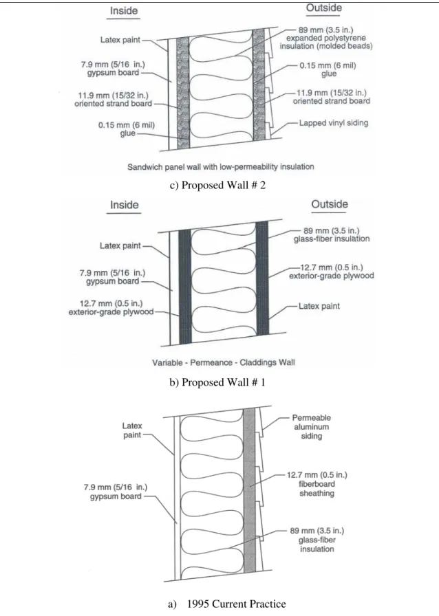
Single Stud Walls with Exterior Insulating Sheathing
A rigid or semi-rigid insulating sheathing board is added on the exterior (Figure 1), with a membrane or rigid air barrier system. A balloon-framing method could be used to reduce thermal bridging. For a 38 x 139 mm (2 x 6) framing, minor modifications to standard construction practices would include the following.
• Space studs on 600 mm (24 in.) on centres.
• Replace structural sheathing with diagonal wood or metal bracing and insulating sheathing, except where structure sheathing is required.
• Recess header joists to allow for higher insulation level at the joists. • Install continuous vapour and air barriers.
• Upgrade insulation between the studs. Spray-type insulations provide a uniform insulation level and reduce air leakage. High-density spray-type insulations may provide higher thermal resistance per unit thickness than batt-type insulation.
Single stud wall with exterior insulating sheathing (Source: CHBA (2001: 189, Fig. 11.9).
Figure 2. Thermally Upgraded Single Stud Wall
Single Stud Walls with Interior Strapping
First, 38 x 38 mm (nominal 2 x 2) or 38 x 64 mm (nominal 2 x 3) strapping is installed, usually horizontally on the interior of the stud walls. Either membrane or rigid air barrier system can be used. When polyethylene is used as a vapour and air barrier, it is usually placed on the inside face of the studs before the strapping. This approach has advantages: in addition to the RSI-3.5 (R-20) insulation in the 38 x 139 mm (2 x 6) main wall, RSI 1.4 (R-8) batt-insulation can be added in the 38 x 64 mm (nominal 2 x 3) strapped space, which would also reduce thermal bridging.
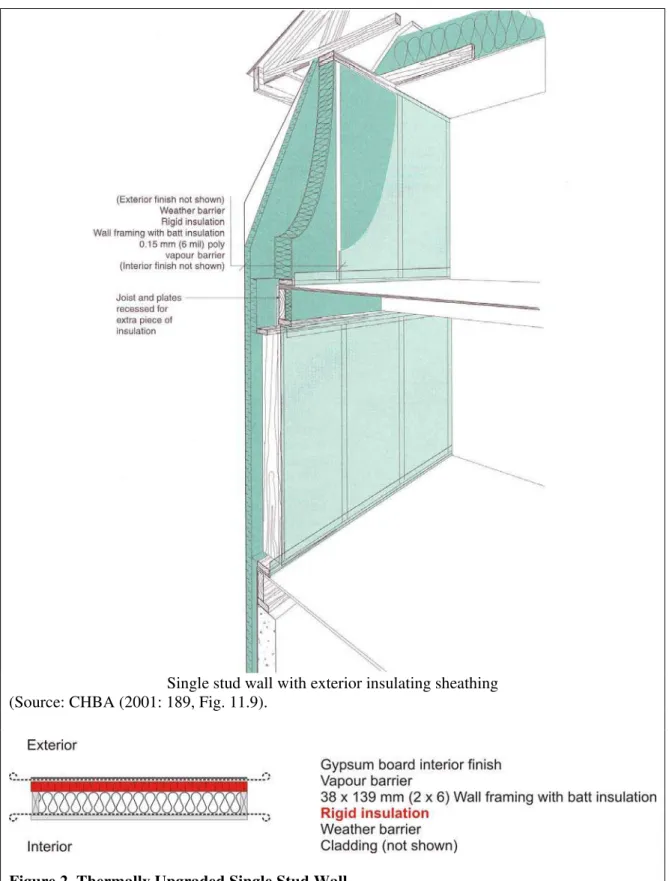
Double Stud Walls
This system (Figure 2) consists of a load-bearing structural wall constructed with conventional framing techniques, a lighter non-load-bearing wall that supports exterior siding or interior drywall, and either a membrane or rigid air barrier system. The wall thickness depends on the required R-value.
Insulation options include batt insulation. The centre cavity between the two walls, generally 89 or 139 mm (3½ or 5½ in.), will fit RSI-2.1 or RSI-3.5 (R-12 or R-20) insulation batts that are installed horizontally; batts are then installed vertically between the studs. Spray-in-place insulation can also be used. This includes foam, loose fill fibre, or cellulose insulation.
A double stud wall system provides for a flexible wall thickness to accommodate a high level of insulation, ensures a continuous air barrier throughout the building envelope, as it would not be penetrated by electrical or plumbing systems, allows for the use of smaller dimensional lumber, and reduces thermal bridging. However, a double stud wall system means higher labour and material costs. Platform framing techniques may also not be suitable for erecting the exterior wall. Two examples of a double stud wall system (Saskatoon House and Hanover House) are reviewed later in this section.
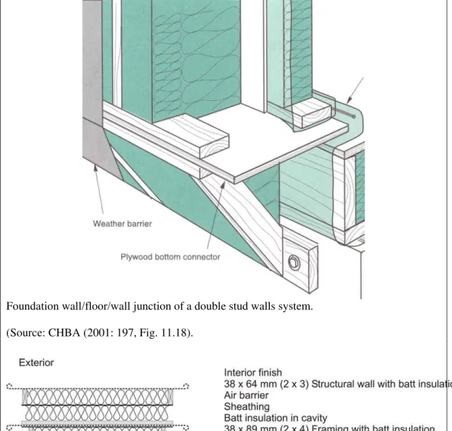
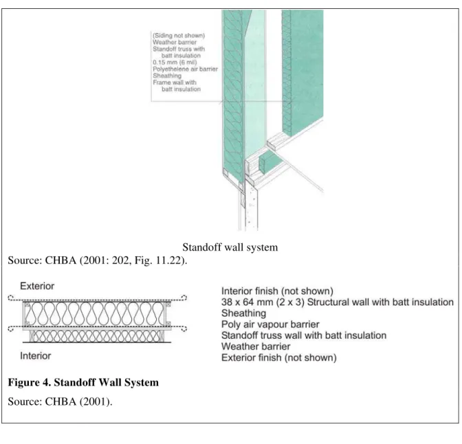
Standoff Walls
This system, as illustrated in Figure 3, is a variation of the double stud wall system. It consists of:
• a load-bearing interior wall constructed with conventional stud framing techniques (smaller dimension lumber can be used);
• sheathing on the interior of the stud wall;
• a non-load-bearing truss-stud exterior wall either site-fabricated or factory
manufactured, designed to accommodate required insulation, is placed offset relative to the interior stud wall to cover the edge of the floor slab to minimize its thermal bridging; and
• either a membrane or rigid air barrier system. If polyethylene is used, it should be installed over the sheathing ensuring that there is sufficient insulation to the exterior to maintain it above the dew point temperature.
A standoff wall system can accommodate a high insulation level, ensures good air barrier continuity with minimum seams and penetrations, allows for the use of smaller
dimensional lumber and uses conventional stud framing techniques. However, in the truss stud wall, differential shrinkage between inner and outer truss members and the header joist can cause deformation and crack development in the interior finish material (e.g., drywall). An example (Illinois House) of a wall system using engineered floor I-beam as studs is reviewed later in this section.
Foundation wall/floor/wall junction of a double stud walls system.
(Source: CHBA (2001: 197, Fig. 11.18).
Figure 3. Double Stud Walls Assembly
Standoff wall system Source: CHBA (2001: 202, Fig. 11.22).
Figure 4. Standoff Wall System
Source: CHBA (2001).
Rigid Insulating Core Panel Walls
These systems use foam-insulated, factory-manufactured panels with locking details at the edges to ensure tight fit of joints. Various manufacturing methods are used to build the framing into the foam panel.
Advantages of rigid insulating core panel walls include uniform insulation, good air barrier continuity when joints are well sealed, reduced thermal bridging, and lower
installation labour as the studs and insulation are erected together. Manufacturers can also reduce costs by recycling scraps. However, thermal bridging may occur through top and bottom plates, and the system requires accurate drawings and dimensions.
Structural Insulated Panel Systems
Also known as SIPs, these systems are stress-skin panels consisting of polystyrene, polyurethane, or glass fibre insulating cores sandwiched between skins of wood, wood panel sheathing, waferboard, or drywall. The panels come in a wide range of
for rigidity, and can be used as sheathing over a wall or roof or as the entire envelope of the house including structural elements.
Advantages of SIP panels include their uniform insulation, they provide a good air barrier continuity when joints are well sealed. The panels also save construction time. However, thermal bridging may occur through the top and bottom plates and vertical stiffeners if used, and the panels require accurate drawings and dimensions. The literature on SIPs and their application in Northern Canada is reviewed later in this section.
Concrete Wall Construction
These systems use insulating concrete forms (ICFs), which provide the formwork for the concrete, insulation, and sheathing in a single system. An ICF system saves construction time by combining the construction of the framing, insulation, sheathing, and air barrier elements into one step. This results in a good R-value and minimum thermal bridging. Little specialized labour or special tools are required, the forming material is lightweight, and there is less construction waste. However, changes are difficult to make on site once concrete has been poured, and the initial cost is high.
Best Practices in Wood Frame Envelopes
The Best Practice Guide - Wood-Frame Envelopes from CMHC (1999-1) addresses principles, practical features, and detailed considerations of constructing wood frame building envelopes across Canada, except along coastal British Columbia. Another best practices guide (CMHC, 2001) addresses wood frame envelopes in the high moisture climate of coastal British Columbia. The best practice guide (CMHC, 1999-1) provides details of three samples of wood frame wall assemblies.
Wall Assembly A: Common Basic Stud Wall
The wall assembly from exterior-to-interior consists of:
• brick veneer cladding, attached with galvanized brick ties nailed into the stud; • an air space, 38 mm (1½ in.);
• 15 lb perforated asphalt building paper moisture or weather barrier; • OSB sheathing, 11 mm (7/16 in.);
• wood studs, 38 x 139 mm (2 x 6) at 400 mm (16 in.) or 600 mm (24 in.) on centre; • batt insulation or blown insulation in the stud spaces, RSI-3.5 (R-20);
• polyethylene air/vapour barrier, 0.15 mm (6 mil); and • gypsum board, 12.7 mm (½ in.).
The foundation from exterior-to-interior consists of:
• a rigid mineral fibre drainage layer;
• damp proofing to grade: building paper, polyethylene, or asphalt impregnated building paper;
• a poured concrete foundation wall, 200 mm (8 in.);
• polyethylene moisture barrier, 0.15 mm (6 mil), perforated above grade; • wood studs, 38 x 89 mm (2 x 4) at 600 mm (24 in.) on centre;
• polyethylene air/vapour barrier, 0.05 mm (2 mil); and • gypsum board, 12.7 mm (½ in.).
Disadvantage:
• Thermal bridging through the studs reduces the wall’s thermal performance.
Wall Assembly B: Exterior Insulation System with Airtight Drywall The wall assembly from the exterior to interior consists of:
• horizontal wood siding;
• vertical 19 x 64 mm (1 x 3) wood strapping;
• 38 mm (1 ½ in.) semi-rigid glass fibre insulation sheathing (RSI-1.18 (R-8)) with spun-bonded polyolefin laminated to the insulation face to function as a moisture barrier and the joints taped;
• 38 x 139 mm (2 x 6) wood studs at 400 mm (16 in.) or 600 mm (24 in.) on centre; • RSI-3.5 (R-20) batt insulation, or blown insulation in the stud spaces;
• 12.7 mm (½ in.) gypsum board, functioning as an air barrier (airtight drywall approach); and
• vapour barrier, usually paint.
The foundation from exterior-to-interior consists of:
• a rigid mineral fibre drainage layer; • damp proofing to grade;
• 200 mm (8 in.) poured concrete foundation wall;
• 0.15 mm (6 mil) polyethylene moisture barrier perforated above grade; • 38 x 89 mm (2 x 4) wood studs at 600 mm (24 in.) on centre;
• RSI-2.11 (R-12) batt insulation; • 12.7 mm (½ in.) gypsum board; and
• a vapour barrier, usually paint. An insulation-filled polyethylene pillow friction-fit between the joists can also be used.
Advantages:
• Compared to Assembly A, thermal performance is enhanced by increasing the insulation level and reducing thermal bridging at the studs.
• The glass fibre sheathing is highly permeable to water vapour and helps dry out the wall assembly.
Disadvantages:
Wall Assembly C: Exterior Airtight Sheathing Element System
The Canada Mortgage and Housing Corporation (1999-1) noted that this system has been used in a limited number of research buildings. The system shows promise for ease of construction and air-barrier performance. The guide proposes the system as an alternative approach to the common wood frame construction approaches.
The wall assembly from exterior to interior consists of: • stucco finish cladding;
• self-furring lath;
• 15 lb. perforated asphalt building paper moisture barrier;
• sheathing consisting of two layers of 12.7 mm (½ in.) fibreboard sheathing with a spun-bonded polyolefin sheathing membrane (Tyvek®) sandwiched in between (also functions as air barrier);
• 38 x 139 mm (2 x 6) wood studs at 400 mm (16 in.) or 600 mm (24 in.) on centre; • RSI-3.5 (R-20) batt insulation, or blown insulation in the stud spaces;
• 0.15 mm (6 mil) polyethylene vapour barrier; and • 12.7 mm (½ in.) gypsum board.
The foundation from exterior-to-interior consists of:
• a moulded plastic drainage layer; • damp proofing to grade;
• 200 mm (8 in.) poured concrete foundation wall, functioning as an air barrier; • 15 lb. non-perforated asphalt building paper moisture barrier;
• 38 x 89 mm (2 x 4) wood studs at 600 mm (24 in.) on centre; • RSI-2.11 (R-12) batt insulation;
• 0.05 mm (2 mil) polyethylene vapour barrier; and • 12.7 mm (½ in.) gypsum board.
Advantages:
• This approach ensures continuity of the air barrier by locating it in the outside assembly. This approach also makes it suitable for the retrofit of existing structures. • No special details are required for electric wiring, partitions, etc.
• The fibreboard sheathing is high water vapour permeable compared to plywood, OSB, foamed plastic, and laminated polyethylene-laminated fibreboard.
Disadvantages:
Building Envelopes: Northern Canada
Strub (1996) wrote a textbook, Bare Poles: Building Design for High Latitude, that provides strategies for designing buildings in Canada’s northern regions. The textbook addresses the social and physical mix of peoples, terrain, climate, and building elements, and the constraints for high latitude regions. The book also includes climate charts for northern cities (e.g., Baker Lake, Broughton Island, Cambridge Bay, Fort Liard, Fort Simpson, Grise Fiord, Inuvik, Iqaluit, Rosulte, Yellowknife, and Whitehorse) as well as cities in southern regions for comparison (e.g., Edmonton, Halifax, Montréal, Regina, Sudbury, Toronto, Vancouver, and Winnipeg).
The web site of the Northern Research and Technology in Housing (NoRTH) <www.north-rthn.org> provides a centralized source of knowledge on housing
construction in the northern regions. Topics address everything from building envelope components and mechanical systems to community issues and planning. The NoRTH is an association of northern and remote organizations that includes CMHC and the Alaska Housing Finance Corporation. The web site includes CMHC northern housing-related documents as well as case studies of the performance of super-insulated houses in northern communities.
CMHC’s North Series
Canada Mortgage and Housing Corporation published a series of publications called the North Series (CMHC, 2001-2003), which includes eight publications that deal with both technical and socio-economic issues related to building technologies and practices for the climate conditions in Canada’s northern regions. The series presents example
technologies for the north, including the application of structural insulated panels, wastewater reclamation and co-generation demonstration projects, roof and foundation systems, integrated heating and domestic hot water, and guidance for building healthy housing in the north. The North Series complements the more in-depth North Research Reports by CMHC.
• North Series # 1 Building with Structural Panels Repulse Bay presents the
performance of an application of SIPs in the northern community of Repulse Bay, Nunavut, as compared to the wood frame construction normally used in northern communities. The common wood frame construction uses dimensional lumber for structure, plywood or OSB for sheathing, and fibreglass batts for insulation. The SIP wall construction is described in detail below.
• North Series # 2 On-Site Wastewater Reclamation Systems for the North discusses the challenges of wastewater disposal and describes an environmentally friendly on-site wastewater technology for the north.
• North Series # 3 Snowshoe Inn, Fort Providence Co-Generation Model describes a co-generation demonstration project in Fort Providence, Yellowknife. The project combined heat and electric power generation for the community, and helped conserve energy resources.
• North Series # 4 Residential Foundation Systems for Permafrost Regions discusses the advantages, disadvantages, and anticipated life span and life cycle costs of various foundation options for northern climate conditions. Decision flow diagrams aid in the selection of the appropriate type of foundation depending on soil conditions and the availability of appropriate equipment and skilled labour. Foundation systems are described below.
• North Series # 5 Eagle Lake Healthy House provides guidance for building healthy housing in the north, and describes a house demonstration project in Eagle Lake First Nations, Northern Ontario. The house is described below.
• North Series # 6 Arctic Hot Roof Design presents an arctic roof design that can
withstand northern environmental conditions, where there is little annual precipitation and prevalent blowing snow conditions in long winters. The arctic hot roof system has been used successfully in the north in houses and large buildings for about 15 years. Roof systems are described below.
• North Series # 8 How to Prevent Plumbing and Heating Vent Stack Freeze-Up presents strategies for preventing the freeze-up of plumbing and heating vent stacks. This is discussed in more detail in the next section.
• North Series # 9 Fancoil Integrated Combination Heat and Domestic Hot Water
Systems describes the integration of the traditional two separate systems for space heating and domestic hot water into one energy-efficient system. This is discussed in more detail in the next section.
Building Envelope Examples, Northern Canada
The wood frame building envelope system is common in northern Canada. The wall assembly includes 38 x 139 mm (2 x 6) lumber for structure, plywood or OSB for sheathing, and mineral wool or fibreglass batt for insulation in the stud space as well as semi-rigid insulation over the wood strapping. An air barrier membrane is applied on the cold side of the insulation and a vapour barrier membrane is applied on the warm side of the insulation. Galvanized steel siding is common. In some areas, structural panel siding of engineered wood strands replaces sheathing and is nailed directly to the studs. The panels are prefinished and treated to resist moisture and fungal rot.
Wood Frame Assembly
The following are two examples of wood frame construction common in Northern Canada.
Nunavik, Quebec example: Angers (1999) described the wood frame construction used in Nunavik, an area consisting of one third of the Province of Quebec. To put it in perspective, Nunavik is the same size as all of France, and 1.5 time bigger than Japan.
• Climate: The Arctic climate in Nunavik is characterized by a long eight months of winter and temperatures that can reach -40ºC (-40ºF). Ground is permanently frozen (permafrost).
• Transportation challenges: Prefabricated construction materials are transported by boat from Montréal, which takes about seven days. Extra care is needed, because there is no port infrastructure in Nunavik.
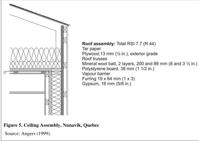
Figure 5. Ceiling Assembly, Nunavik, Quebec
Source: Angers (1999).
• Foundation: Buildings are elevated on steel frames equipped with adjustable jacks. Elevating the building minimizes effects on the permafrost instability and reduces snowdrift accumulation near the building. Vegetation is also left intact under the compacted backfill, which helps to stabilize the terrain.
• Wind and snow drifting: Buildings are designed without eves and the roof slope is moderate (one in three) to prevent vibration during storms and excessive snow accumulation.
• Roof: The thermal resistance of the roof (Figure 4) is RSI-7.7 (R-44) as compared to RSI-7.1 (R-40) in southern Quebec.
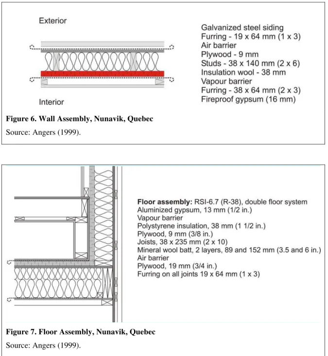
• Exterior walls: The thermal resistance of walls is 4.9 (R-28) compared to RSI-4.5 (R-26) in southern Quebec. Figure 5 shows the assembly of exterior walls.
Figure 6. Wall Assembly, Nunavik, Quebec
Source: Angers (1999).
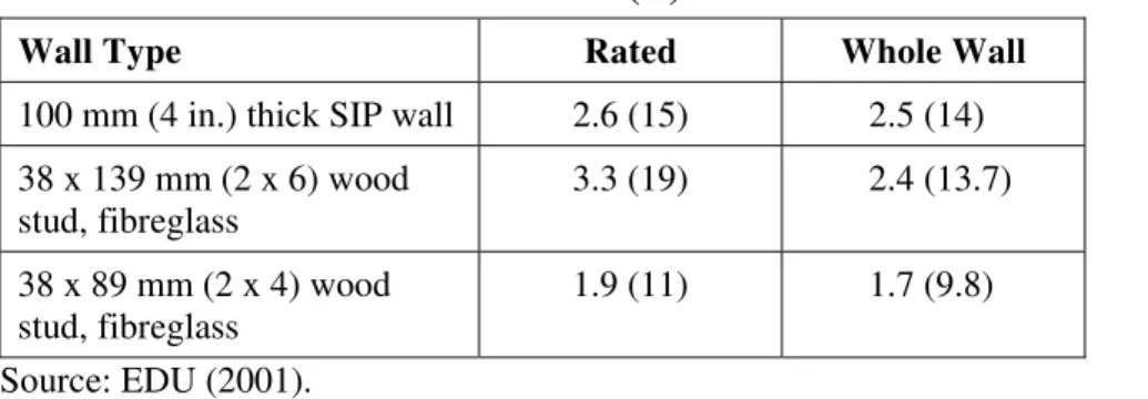
Figure 7. Floor Assembly, Nunavik, Quebec
Source: Angers (1999).
• Floor: The floor (Figure 6) is a double system, which creates a service chase for the air ducts of an oil heating system. The thermal resistance of the double floor system is RSI-6.7 (R-38) for public buildings or RSI-5.4 (R-31) for houses. In southern
Quebec, RSI-4.7 (R-27) is required for floors.
• Windows: Triple-glazed windows provide thermal resistance of RSI-0.5 (R-3) as compared to double-glazed windows in southern Quebec. Window openings are reduced to a minimum.
• Plumbing system: To solve condensation problems, plumbing is insulated and, depending on the building’s heating system, a glycol or warm air is used to heat pipes.
• Porch: Houses include an unheated, insulated porch at the main entrance to act as an air lock to keep cold air out when the door is opened, and also to minimize
condensation.
Angers (1999) noted that a new approach is being tried in which building modules are prefabricated in a factory in southern Quebec and transported on barges to the north. The goal is to reduce completion costs on site.
Nunavut Example: A building envelope assembly adopted by Nunavut Housing Corporation (2005) consists of the following. A similar assembly is described in the builders’ manual prepared by the ACHP (1995).
• Exterior wall assembly:
- total RSI-5.1 (R-29), from exterior to interior; - prefinished structural panel sidingi;
- air barrier; a complete house rap system;
- wood studs, 38 x 140 mm (2 x 6) at 600 mm (24 in.) on centre; - mineral wool batt, 140 mm (5½ in.), RSI-3.9 (R-22);
- poly vapour barrier, 6 milii;
- strapping 38 x 38 mm (2 x 2) at 600 mm (24 in.) on centre; - semi-rigid insulation, 38 mm (1½ in.) RSI-1.2 (R-7); and - gypsum board, 12.7 mm (½ in.), abuse resistant, painted. • Roof assembly: Total RSI-7.7 (R-44), from exterior to interior;
- metal roof;
- strapping 19 x 64 mm (1 x 3) at 600 mm (24 in.) on centre; - air barrier;
- plywood sheathing, 9.5 mm (3/8 in.); - joists;
- mineral wool batt two layers, 150 mm (6 in.) RSI-3.9 (R-22) (fills void completely); - plywood sheathing, 12.7 mm (½ in), 3 mm (1/8 in.) gap at joints;
- vapour barrier; and
- gypsum board, 12.7 mm (½ in), abuse resistant, painted.
• Floor insulated assembly: Total RSI-9 (R-51), from interior to exterior: - vinyl tile;
- underlay (6 mm (¼ in)) over 16 mm (5/8 in.) tongue and groove plywood (glue and screw/nail to floor joists);
- floor joists;
- mineral wool insulation, two layers 150 mm (6 in.), RSI-3.9 (R-22) (fill void completely);