Publisher’s version / Version de l'éditeur:
Vous avez des questions? Nous pouvons vous aider. Pour communiquer directement avec un auteur, consultez la première page de la revue dans laquelle son article a été publié afin de trouver ses coordonnées. Si vous n’arrivez pas à les repérer, communiquez avec nous à PublicationsArchive-ArchivesPublications@nrc-cnrc.gc.ca.
Questions? Contact the NRC Publications Archive team at
PublicationsArchive-ArchivesPublications@nrc-cnrc.gc.ca. If you wish to email the authors directly, please see the first page of the publication for their contact information.
https://publications-cnrc.canada.ca/fra/droits
L’accès à ce site Web et l’utilisation de son contenu sont assujettis aux conditions présentées dans le site LISEZ CES CONDITIONS ATTENTIVEMENT AVANT D’UTILISER CE SITE WEB.
10th International Vacuum Insulation Symposium [Proceedings], 2011-09-15
READ THESE TERMS AND CONDITIONS CAREFULLY BEFORE USING THIS WEBSITE. https://nrc-publications.canada.ca/eng/copyright
NRC Publications Archive Record / Notice des Archives des publications du CNRC : https://nrc-publications.canada.ca/eng/view/object/?id=506e88a8-52de-493f-af33-14fe36c40977 https://publications-cnrc.canada.ca/fra/voir/objet/?id=506e88a8-52de-493f-af33-14fe36c40977
NRC Publications Archive
Archives des publications du CNRC
This publication could be one of several versions: author’s original, accepted manuscript or the publisher’s version. / La version de cette publication peut être l’une des suivantes : la version prépublication de l’auteur, la version acceptée du manuscrit ou la version de l’éditeur.
Access and use of this website and the material on it are subject to the Terms and Conditions set forth at Application of vacuum insulation panels in low-sloped commercial roofing systems
Application of vacuum insulation
panels in low-sloped commercial
roofing systems
Molleti, S,; Mukhopadhyaya, P.; Baskaran, B.A.; Beaulieu, P.; Sherrer, G.
NRCC-54494
A version of this document is published in 10th International Vacuum Insulation Symposium, Ottawa, Ontario, September-15-16, 2011
The material in this document is covered by the provisions of the Copyright Act, by Canadian laws, policies, regulations and international agreements. Such provisions serve to identify the information source and, in specific instances, to prohibit reproduction of materials without written permission. For more information visit http://laws.justice.gc.ca/en/showtdm/cs/C-42
Les renseignements dans ce document sont protégés par la Loi sur le droit d’auteur, par les lois, les politiques et les règlements du Canada et des accords internationaux. Ces dispositions permettent d’identifier la source de l’information et, dans certains cas, d’interdire la copie de documents sans permission écrite. Pour obtenir de plus amples renseignements : http://lois.justice.gc.ca/fr/showtdm/cs/C-42
APPLICATION OF VACCUM INSULATION PANELS IN LOW SLOPE ADHESIVE APPLIED ROOFING SYSTEMS
S. MOLLETI, P. MUKHOPADYAYA, A. BASKARAN, P. BEAULIEU AND G.SHERRER
National Research Council Canada,Building Envelope and Structure Program, Ottawa,Canada Tel: 613-993-9673, Fax: 613-998-6802, Email: sudhakar.molleti@nrc.ca
Abstract
In North America, low sloped roofs represent the vast majority of the commercial roofing. With vast roof surface area exposed to the Mother Nature, the low sloped roofs represent a major portion of the urban footprint. To control the heating and cooling loads, the conventional insulation are typically used in these low sloped roofing assemblies or commercial roofing assemblies where they are installed in multiple layers having R-value ranging from R-15 to R-40. With the changing climatic pattern, it is no wonder that these numbers might increase in the future. To address the possibility that whether the VIP can become the next generation insulation in the roofing systems where it can address both the high R-value and increasing thickness, an innovative experimental study has been started at the National Research Council of Canada. The focus of this study is to evaluate the long term performance of the VIP in the low sloped roofing assembly and its comparison with the conventional insulation. This experimental investigation is part of the Program of Energy Research and Development Canada (PERD) study “The Next Generation Building Envelop System”. Of the different types of commercial roofing systems available in the market, an adhesive applied roofing system was selected for this study. As the name refers, in adhesive roofing system all the components are adhered used adhesives and therefore it offers a fastener free roofing system. The study evaluates the performance of VIP under two different roofing systems - one is the roof of in-service NRC building M-24 re-roofed with modified bituminous system, and the other is the roof mock up on M-24 roof constructed with EPDM system. The paper discusses the experimental setup and application details of the VIP in the field roof and roof mock up. It also presents and discusses some of the preliminary thermal data obtained from these roofing systems.
Introduction
Roofing systems generally can be divided into two groups: low slope and steep slope roofing systems. Typically, residential roofs belong to the steep slope roof system group whereas, the commercial or industrial buildings such as, office buildings, warehouses, retail buildings, plants and factories, often have low slope roofs. This paper focuses on the low sloped commercial roofs.
The roofing community in North America has undergone much change over the last 25 years along, with advances in material science, computer-aided designs and engineering applications. According to a 2000 market survey for the Canadian Roofing
Contractors’ Association (CRCA)[1], the modified bitumen roofing systems have
from the National Roofing Contractors Association (NRCA)[1] in the US shows that the single-ply low slope roofs have 40% of the market share. Figure 1 shows the changes in the market share for low-slope roofs based on the 2008–09 NRCA market survey. During these eight years, single-ply roofing for new and re-roofing constructions have been increasing and clearly have the largest market share in commercial roofing.
FIGURE 1: MARKET SHARE FOR LOW-SLOPE ROOFS IN NORTH AMERICA
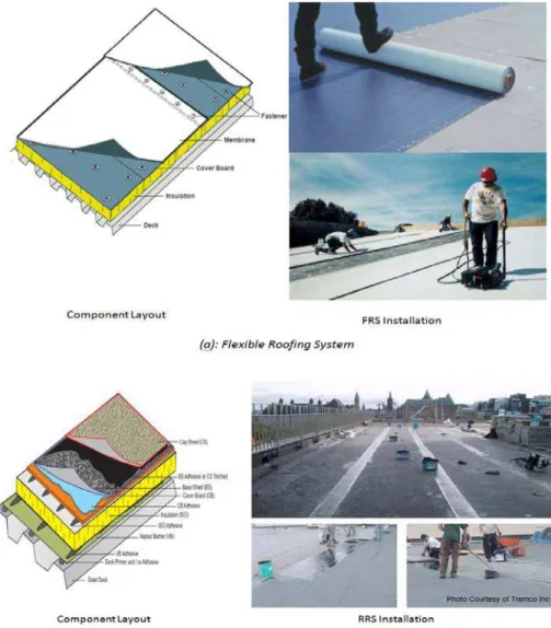
Within the single-ply roofing, in accordance with the attachment methods of the roof components, it can be grouped into two categories: Flexible Roofing System (FRS) and Rigid Roofing System (RRS) as shown in Figure 2. Typical roofing components in these conventional single-ply roofing systems are, (from interior to exterior)
Structural deck – steel deck is a common material used to support these roofing systems.
Vapor barrier or air retarder - Controlling air and vapor movement is critical in roof design. Different options are available such as self adhered film, polyethylene and building paper.
Insulation – The control of heat loss and gain through a roof system depends almost exclusively on the insulation. Plastic (polyisocyanurate or polystyrene) insulation is used in the majority of these conventional roofing assemblies.
Protection or cover board – Cover boards enhance the compressive strength performance of the roof assembly. Typical cover boards used in the conventional roofing assemblies are fiberboard, asphalt core board and cementious board. Waterproofing membrane. The waterproofing membrane is available in three
different types: Modified bituminous (Mod-Bit), Thermoplastic [polyvinyl chloride (PVC) and thermoplastic olefin (TPO)] and Thermoset [ethylene propylene diene terpolymer [EPDM]). The Mod-Bit is asphaltic based and comprises of two ply membranes- base and cap sheet, which on integrating as a roof system performs as a one ply membrane. Both the base and cap sheets come in standard width of 1 m (3ft). The thermosets and thermoplastics are single ply membranes composed predominately of synthetic polymer. These are strong, flexible sheets with thickness in the range 45 mil to 80 mil. All the membranes are sealed at joints or overlaps to form continuous waterproofing. Both these membranes are available in different sheet widths ranging from 2m to 4 m (6 ft to 12 ft).
FIGURE 2: TYPICAL VIEW OF COMMERCIAL ROOFS
In a FRS, the roofing components are integrated using mechanical fasteners, whereas, in a RRS the components are integrated using adhesives. FRS and RRS can react differently when exposed to the same magnitude of wind uplift due to their particular load transferring mechanisms or response. These reactions are caused by different attachment methods, configurations, and application technologies.
As discussed above, to control the heating and cooling loads in these commercial roofing assemblies, the plastic (polyisocyanurate or polystyrene) insulation is used where they are installed in single or multiple layers to meet the thermal performance requirement. In Canada, the National Energy Code of Canada for Buildings (NECB]
has prescriptive R-value requirements for the different climate zones across Canada. For roofs, the R-value requirement varies from R21 to R40 across Canada, and therefore to meet this requirement 4 inches to 8 inches of plastic insulation is required to be installed in the roofing assemblies. With the changing climatic pattern, it is no wonder that these numbers might increase in the future. Increasing insulation thickness may adversely affect the roofing system performance in terms of insulation shrinkage, differential movement within multiple insulation layers and other roofing components, membrane wrinkling and membrane pulling as shown in Figure 3 [2] .
FIGURE 3: EFFECT OF INCREASING INSULATION THICKNESS ON ROOFING SYSTEM [2]
To investigate that whether the vacuum insulation panel VIP can become the next generation insulation in the roofing systems where it can address both the high R-value and increasing thickness, an innovative experimental study has been started at the National Research Council of Canada. The focus of this study is to evaluate the long term performance of the VIP in the low sloped roofing assembly and its comparison with the conventional insulation. This experimental investigation is part of the PERD (Program of Energy Research and Development) study “The Next Generation Building Envelop System”.
VIP in Roofing Applications
Vacuum Insulation Panel (VIP) is a high thermal performance insulation that was developed several years ago for use in appliances such as refrigerators and deep freezers. It was introduced into the construction technology in the last few years [3]. The thermal resistance of VIP is a factor of five to ten better than conventional insulation of the same thickness. Used in buildings they enable thin, highly insulating construction in walls, roofs and floors. VIP in general are flat elements consisting of open porous core material enclosed in a gas barrier/facer foil for air – vapor tightness (Figure 4)[4].The core material imparts mechanical strength and thermal insulating capacity. Within the enclosure, the core material has to maintain the required quality of vacuum withstanding the external load caused by atmospheric pressure. A getter/desiccant is added inside the core material to adsorb residual or permeating atmospheric gases or water vapor in the enclosure. The long term performance of the VIP’s is very much dependent on the performance of the gas barrier.
FIGURE 4: VACUUM INSULATION PANEL (VIP) AND IT’S TYPICAL R-VALUE COMPARISION TO THOSE OF OTHER INSULATING MATERIALS [4]
Application of VIP in low –sloped roofing is a little bit of complex task as the roof system installation involves a lot of foot traffic and other roof penetrations. However, with the concept of pre-fabricated VIP panels and proper installation techniques roofing could offer a great new opportunity for the global thermal VIP insulation industry. Considering the sensitiveness or limitation of the VIP to penetrations, the present experimental study selected rigid roofing system (RRS) to evaluate the long term field thermal performance of VIP. As mentioned above, in RRS all the roofing components are adhered using adhesives and therefore it offers a fastener free
roofing system. Combining VIP with the conventional polyisocyanurate insulation and particle fiber board, composite VIP panels were constructed and installed in modified bitumen roofing system on the field roof of the NRC building M-24, and on two roof mockups that had EPDM roofing system. This paper discusses the experimental setup and application details of the composite VIP, and presents some of the preliminary thermal data obtained from these three roofing systems
Experimental Set-up
The scope of this study is to evaluate the long term performance of the VIP in the low sloped roofing assembly and its comparison with the conventional insulation. To provide this comparative evaluation, the present study selected an existing roof of NRC Building M-24 located in Ottawa. Apart from this field roof, two roof mockups were also constructed with one mockup comprising of conventional polyisocyanurate and other mock up constructed with composite VIP. Both these mockups are placed on the rooftop of Building M-24. The difference between the field roof and the roof mockups is the roofing system type and the construction, which will be discussed below.
M-24 - Field Roof –Modified Bituminous Roofing System
The roof of building M-24 was 15 year old Built-up roofing system and it was undergoing re-roofing with the new generation rigid roofing system. Figure 6 shows the building M24 and the cross-sectional layout of this new roof, which comprises of a concrete deck, vapor barrier, 75 mm (3 in) rigid polyisocyanurate insulation, 6 mm (1/4 in) asphalt cover board, modified bituminous membrane base sheet and modified bituminous membrane cap sheet. This was a modified bituminous roofing system. All the roofing components are integrated with solvent based roofing adhesive. Replacing one of the 75 mm (3 in) polyisocyanurate insulation, a 1.2 m x 2.4 m (4 ft x 8 ft) composite VIP was installed within the roofing system. The 75 mm (3 in) thick composite VIP as shown in Figure 6 comprised of two layers of 12 mm (1/2 in) thick VIP panels sandwiched between two layers of 1 in thick polyisocyanurate on the top and bottom. The VIP panels were available in dimensions of 450 mm x 560 mm (18 in x 22 in). The layout of a 1.2 m x 2.4 m (4ft x 8ft) composite VIP with a single layer of VIP panels has numerous joints, which could lead to thermal bridging issues. To minimize the effect of thermal bridging, a second layer VIP was incorporated in the construction of composite VIP. Figure 7 shows the construction details with the temperature and heat flux sensors instrumentation. One of the critical parts in the composite VIP construction was the adhesive selection. To make sure that the selected adhesive is compatible with both the paper faced polyisocyanurate and foil faced VIP, an in-house thermal conditioning testing was conducted on three solvent based insulation adhesives that are used in the roofing construction. Based on the visual observations and small scale mechanical testing, the appropriate adhesive was selected for the construction process. The construction process involved the following steps:
1. The bottom layer insulation is primed with adhesive followed by the adhesive application on the first layer of VIP panels. When both the surfaces – insulation and VIP are tacky to touch, the VIP panel are adhered to the bottom insulation layer following the inside edges of the insulation board. As the VIP panels are 450 mm x 560 mm (18 in x 22 in) and the insulation board is 1.2 m x 2.4 m (4 ft x 8 ft), the first layer VIP layout comprised of 10 boards leaving 6 in gap along the length and width of the insulation board.
2. With the first layer VIP laid, adhesive is applied on the top surface of the VIP panels and also on the bottom surface of the second layer VIP panels. When both the surface are tacky the second layer VIP panels are applied with a offset of 150 mm (6 in) from the first layer such that second layer VIP panels cover all the gaps of the first layer panels. This procedure was followed to minimize the thermal bridging from the panel gaps.
3. Once the second layer VIP panels are fully adhered, it is covered by the second layer of 1.2 m x 2.4 m (4 ft x 8 ft) polyisocynaurate board, and weight were put on top of insulation board to obtain proper bonding strength between the layers of the composite VIP.
4. Spray polyurethane was applied all along the perimeter of the composite VIP to seal the 150 mm (6 in) space between the VIP and polyisocyanurate.
FIGURE 6: RE-ROOFING OF BUILDING M24 AT NRC WITH RIGID ROOFING SYSTEM FIGURE 7: CONSTRUCTION OF COMPOSITE VIP FOR ROOFING APPLICATION
Figure 8 shows the instrumentation setup. During the construction process two thermocouples were installed within each layer making it a total of 10 sensors to measure the temperature gradient, and 4 heat flux sensors on each polyisocyanurate layer ( total of eight) to measure the heat flow through the composite VIP. Of the 4 heat flux sensors on each insulation layer, one is designed to measure the heat flow through the core or the middle of the VIP panel and the other three to measure the thermal bridging through the VIP panel joints. As one of the objectives was to compare the thermal performance of composite VIP with the conventional insulation side by side, one of the field insulation boards 1.2 m x 1.2 m – 75 mm (4 ft x 4ft – 3 in) thick polyisocyanurate board obtained from the roofing contractor was instrumented with thermocouples and heat flux sensors on both surfaces as shown in Figure 8.
FIGURE 8: SCHEMATICS SHOWING THE INSTRUMENTATION LAYOUT
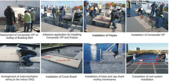
Both the instrumented composite VIP and polyisocyanurate boards were carried over to the rooftop of building M-24 and installed side by side on the field of the roof as shown in Figure 9. All the instrumentation wires were carefully directed to the indoor data acquisition system. With the insulation laid, the cover board was adhered to the insulation followed by the adhesive application of base and cap sheet membranes thus completing the roofing system installation.
FIGURE 9: INSTALLATION OF COMPOSITE VIP AND POLYISO ON M24 ROOF SYSTEM
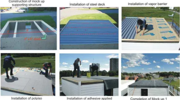
The roof mockups were of size 3.7 m x 3.7 m (12 ft x 12 ft) and were constructed to replicate the field construction of the RRS. Both the mockups had thermoset membrane i.e. black EPDM membrane. In addition to the membrane, both the mockups comprised 22 Ga steel decks and a self adhered film as a vapor barrier. Insulation was the only component that was different in the mockups. Mockup 1 comprised of 50 mm (2 in) thick rigid board polyisocyanurate, while Mock up 2 was constructed with 50 mm (2 in) thick composite VIP. Figure 10 shows the construction of the Mock up 1and Mock up 2. The insulation layout comprised of (1.2 m x 2.4 m - 3 boards (4t x 8ft) and 1.2 m x 2.4 m - 3 boards (4ft x 4ft) -3 boards, which were adhered to the vapor barrier on the steel deck by a low rise two part urethane adhesive. The insulation boards were instrumented with thermocouples and heat flux sensors as shown in Figure 8. In Mock up 2, 2/3rd of the insulation layout was composite VIP constructed of two layers of ½ in thick polyisocyanurate [1.2 m x 2.4 m-– 2 boards (4ft x8 ft) and 1.2 m x 1.2 m - 2 boards (4ft x 4ft)], while the remaining 1/3rd composite VIP was constructed with two layers of ½ in thick particle cover board[ 1.2 m x 1.2 m – 3 boards (4ft x 4ft)] . As the composite VIP panels were constructed with dual layer 12 mm (½ in) thick VIP panels the overall thickness of the composite VIP was 50 mm (2 in) matching the thickness of the polyisocyanurate insulation in Mockup 1. The construction of the composite VIP is similar to what has been described in M24-Field Roof. The adherence of the composite VIP panels to the vapor barrier on the steel deck was also done by using low rise two part urethane adhesive. The thermoset black EPDM membrane was the waterproofing membrane for both the mock ups and it was installed using a solvent based membrane adhesive. The overhang membrane along the mockup perimeter was mechanically fastened to the sides of the mockups, and it was overlaid by vinyl siding to prevent from any water ingress into the system. All the instrumentation wiring were carefully hauled inside the mockups and connected to their individual stand alone data acquisition systems.
FIGURE 10: CONSTRUCTION OF MOCK UP 1-POLYISO AND MOCK UP 2- COMPOSITE VIP
Results and Discussion
The re-roofing of the M24 was completed in late September 2010, while the construction of the two roof mockups was finished in late November 2010. With data acquisition setup, the measurements started from January 2011. M24 roof has a conditioned indoor environment maintained at 20oC and 50 % RH. For the mock ups, during winter period heating elements were placed inside to maintain the indoor temperature at 20oC, however no measures are taken yet for conditioning in the summer and providing indoor humidity. Currently work is going on to address the indoor conditioning issues in both the mockups. The preliminary observations presented in this paper provide a basic understanding of the thermal performance of polyiso versus composite VIP in roofing systems. As the monitoring of the roofs is being continuing, research updates will be presented in the future on the long term performance of the VIP, energy performance and its interaction with the roofing components. The network of thermocouple measured the temperature profile while the heat flux transducers (HFT) recorded the heat flow across the roofing systems. The HFT were calibrated such that a positive reading represents heat entering the
building or the mockups while a negative reading shows heat leaving the building or the mockups.
Temperature and Heat Flow Profile Examples M24: FIELD ROOF
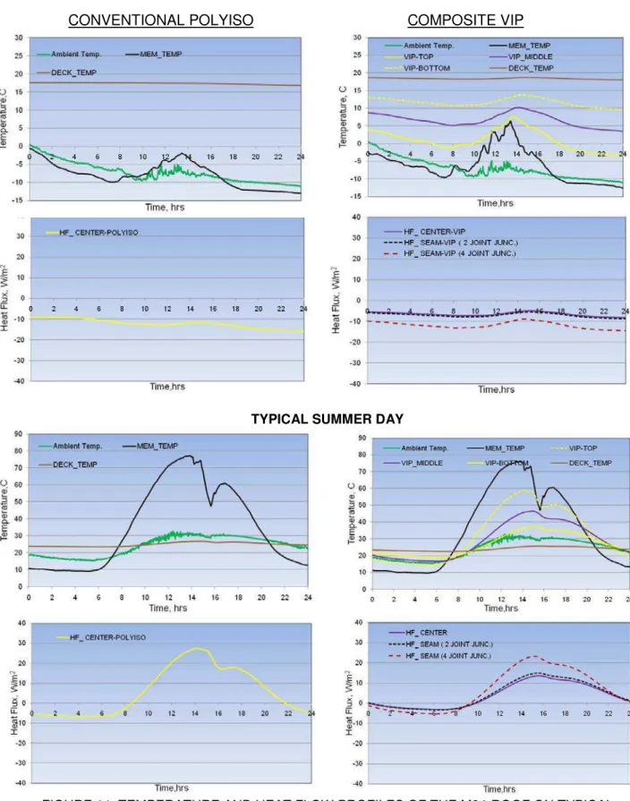
Winter: Figure 11(a) shows the temperature and heat flow profiles of the M24 roofing system on a typical winter day with light snow coverage. As the ambient temperature dropped from midnight to 9:00 a.m.in the morning, the membrane responded to the temperature drop similar on both the polyiso and composite VIP sections. Past 9:00 a.m. as the temperature began increasing to -50C the membrane temperature on the VIP section measured higher compared to the polyiso section. Even though both the boards (polyiso and composite VIP) are adjacent to each other the membrane temperature varied a lot. The maximum and minimum membrane temperature measured on the polyiso section was -0.50 C and -130C respectively, while on the composite VIP it was 60C and -130C respectively. The temperature between the VIP layers show that the panels were warm throughout the day with low of 50C and high of 100C, while the maximum and minimum temperature gradient across the VIP composite was 130C and 70C respectively. It should be noted that the maximum and minimum temperature gradient across the adjacent polyiso board was 300C and 200C respectively. Comparing the heat flow, the data clearly indicates that there was significant heat loss in the polyiso section of the roof measuring a maximum of 16 W/m2 with an average of 12 W/m2. On the other hand the composite VIP minimized the heat flux by almost 50% measuring an average of 6 W/m2. At the VIP panel joints within the composite, the two joint junction (Figure 9) measured similar heat flux as the center of the VIP, while the four joint junction showed significant heat loss with an average of 12 W/m2 almost similar to the polyiso.
Summer: Figure 11(b) shows the temperature and heat flow profiles within the M24 roofing system on a typical summer day with a maximum ambient temperature of 330C. On this hot summer day, the modified bituminous membrane measured a maximum temperature of 780C and minimum of 100C. During the night the membrane temperature was below the ambient temperature indicating the effect of long –wave radiation. This effect of overcooling is reflected in the heat flow of polyiso section of the roof where an average heat loss of 6 W/m2 was measured upto 6:00 a.m. in the morning. With the increase in the ambient temperature, the membrane temperature also increased resulting a maximum temperature gradient of 520C across the polyiso. Heat started enter the building through the polyiso section of the roof not long after 6:00 a.m, reaching a maximum intensity of 27 W/m2 and continued until evening 10:00 p.m at which heat gain change to heat loss. In the case of composite VIP the heat loss due membrane overcooling in the night was only an average of 2 W/m2, while the heat gain during the day reached a maximum intensity of 15 W/m2.The composite VIP significantly reduced the heat flow by an average of 50% (heat gain and heat loss) compared to the polyiso. However, the four joint junctions of the VIP panels once again measured higher heat flux. From the temperature profile, it should be noted that
the top layer VIP panel measured a maximum temperature of 580C followed by middle layer with 460C and the bottom layer with 370C.With VIP panels measuring such high temperatures; it would be interesting to see its effect on the long term performance especially on the gas permeation and insulation efficiency. This will be investigated in the later part of the study as this is one of the research objectives of this field evaluation.
FIGURE 11: TEMPERATURE AND HEAT FLOW PROFILES OF THE M24-ROOF ON TYPICAL WINTER AND SUMMER DAY
M24-ROOF MOCK UPS
In Mock up 2, as explained above 2/3rd of the insulation layout was composite VIP constructed of two layers of ½ in thick polyisocyanurate, while the remaining 1/3rd composite VIP was constructed with two layers of ½ in thick particle cover board. From the data analysis it showed that both the composite VIP configurations measured similar thermal performance, and therefore the following discussion considers the composite polyiso - VIP configuration.
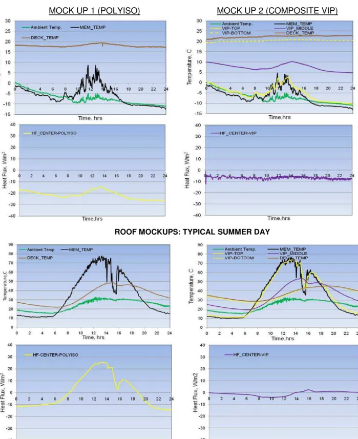
Winter: For the same winter day discussed above for the field roof, Figure 12(a) shows the temperature and heat flow profiles of the M24-Roof Mock ups. During the winter months, indoor temperature of both the mock ups was controlled by room heaters. It should also be noted that both the mock ups have 50 mm (2 in) thick insulation compared to the 75 m (3 in) thick insulation in the field roof. In other words both the mockups have low thermal resistance compared to the field roof. The effect of low thermal resistance is clearly reflected in Mock up 1 where the heat flux varied from 15 W/m2 to 29 W/m2, when averaged the heat loss ( 22 W/m2) was almost doubled compared to the field roof with polyiso section ( 12 W/m2).In Mock up 2, the composite VIP significantly minimized the heat loss by almost 72% compared to Mock up 1. Throughout the day the heat flux intensity varied from 5 to 7 W/m2 averaging around 6 W/m2, which was consistent with the field roof composite VIP section. The temperature between the VIP panels (VIP_MIDDLE) in Mock up 2 followed the same trend as the field roof.
Summer: As mentioned earlier, both the mock ups were not conditioned during the summer months and this resulted in very high indoor temperatures or deck temperatures as shown in Figure 12(b). Therefore relative comparison could not be made of the performance of Mock up 2.Simalr to the field roof, the temperature of the black EPDM membrane fluctuated between 100C in the night to 780C in the day time. In Mock up 1, the overcooling of the membrane during night time led to heat loss of 10 W/m2 (until 6:00 a.m), after which heat started entering into the mockup with the increase in the temperature reaching maximum intensity of 25 W/m2. The membrane overcooling was also observed in Mock up 2 with very low heat loss of 1.5 W/m2 until 6:00 a.m , after which the heat loss continued to a maximum of 4 W/m2 until 2:00 p.m. before heat started entering into the mock up. The maximum heat gain measured was 2.5 W/m2. The heat flux profile of the composite VIP follows the deck temperature profile and the trend indicates that the composite VIP delayed/reduced heat transfer through the roofing system.
FIGURE 12: TEMPERATURE AND HEAT FLOW PROFILES OF THE MOCK UPS 1 AND 2 ON TYPICAL WINTER AND SUMMER DAY
Conclusions
To investigate the research potential that whether the VIP can become the next generation insulation in the low sloped roofing systems where it can address both the high R-value and increasing thickness, an innovative experimental study has been started at the National Research Council of Canada. Prefabricated composite VIP insulation boards were constructed in combination of the polyisocyanurate and VIP panels, and were installed in the NRC building M24 field roof with modified bituminous roof system and EPDM roof mock up This research work started in the early 2011 and the data collection will be continued for monitoring the real time long term performance of VIP in roofing applications. The paper discusses the assembly details of the prefabricated VIP configurations and the construction of the roofing systems, and also it presents some interim results comparing the performance of conventional polyiso insulation with the composite VIP. Acting as a thermal barrier in a roof system the composite VIP displayed its high thermal resistance capacity by minimizing both the heat loss and heat gain in the roof system by more than 50% in comparison to the conventional polyiso. With black roofing membrane on the top, the composite VIP measured high temperatures in the range of 50 to 800C. Monitoring results from periods of several years are needed to verify the effect of these high temperatures on the long term performance especially on the gas permeation, insulation efficiency and any accompanying aging effects. Gaining practical confidence in the vacuum insulation technology is an important prerequisite to further propagate this promising technique in improving the energy efficiency of roofs and buildings.
References
[1] A. Baskaran,B.Murty, D.Prevatt, C.Dixon and P.Datin, “Evaluating wind effects of commercial roofs North American advancements”, Proceedings of 13th International Wind Engineering Conference, Amesterdam, July 11-13th 2011.
[2] P.Kalinger, “When does a green roof make sense ? Lessons Learned”, Presentation at the Construct Canada 2010, Canadian Roofing Contractors Association http://www.roofingcanada.com/
[3] IEA/ECBCS Annex 39, VIP-Study on VIP-components and panelsfor service life prediction of VIP in building applications, and vacuum insulation in the building sector-systems and applications, Subtask A/B reports /www.vip-bau.chS; 2005.
[4] P.Mukhopadhyaya,K.Kumar,F.Ping,N.Normandin, “Use of Vaccum Insulation Panel in Building Envelope Construction: Advantages and Challenges”,Proceedings of the 13th Canadian Conference on Building Science and Technology, Winnipeg,May 10-13th,2011
FIGURE 1: MARKET SHARE FOR LOW-SLOPE ROOFS IN NORTH AMERICA
FIGURE 3: EFFECT OF INCREASING INSULATION THICKNESS ON ROOFING SYSTEM (Kalinger 2010)
FIGURE 5: VACUUM INSULATION PANEL (VIP) AND IT’S TYPICAL R-VALUE COMPARISION TO THOSE OF OTHER INSULATING MATERIALS (Mukhopadhyaya 2011)
FIGURE 6: RE-ROOFING OF BUILDING M24 AT NRC WITH RIGID ROOFING SYSTEM Gas Barrier
FIGURE 8: SCHEMATICS SHOWING THE INSTRUMENTATION LAYOUT
M-24 ROOF: TYPICAL WINTER DAY
CONVENTIONAL POLYISO COMPOSITE VIP
TYPICAL SUMMER DAY
FIGURE 11: TEMPERATURE AND HEAT FLOW PROFILES OF THE M24-ROOF ON TYPICAL WINTER AND SUMMER DAY
ROOF MOCKUPS: TYPICAL WINTER DAY
MOCK UP 1 (POLYISO) MOCK UP 2 (COMPOSITE VIP)
ROOF MOCKUPS: TYPICAL SUMMER DAY
FIGURE 12: TEMPERATURE AND HEAT FLOW PROFILES OF THE MOCK UPS 1 AND 2 ON TYPICAL WINTER AND SUMMER DAY