Advanced Flexible Wing Technology Assessment
for Transport Applications
by
Shawn J. Hanegan
S.B. Aeronautics and Astronautics Massachusetts Institute of Technology, 1995
Submitted to the Department of Aeronautics and Astronautics in partial fulfillment of the requirements for the degree of
Master of Engineering at the
MASSACHUSETTS INSTITUTE OF TECHNOLOGY June 1996
©
Shawn J. Hanegan 1996. All Rights Reserved.The author hereby grants to MIT permission to reproduce and to distribute publicly paper and electronic copies of this thesis
document in whole or in part.
Author ...
'fi A f,
Department of Aeronautics and Astronautics May 28, 1996
Cetl L y ...
Charles Boppe Senior Lecturer, Department of Aeronautics and Astronautics Thesis Supervisor
r
"-C ertified b y ... .... ... ... ... Mark Drela Associate Professor of Aeronautics and Astronautics Thesis Supervisor
Accepted by ... .
--
----
---
-
... .. . .. .Harold Wachman Chairman, Departmental Graduate Committee
F.ASACiUSEETS iNt;Y ii.
OF TECHNOLOGY
JUN 1
1 1996
Aero
I IRARIESAdvanced Flexible Wing Technology Assessment
for Transport Applications
by
Shawn Hanegan
Submitted to the Department of Aeronautics and Astronautics on May 28, 1996, in partial fulfillment of the requirements for the
degree of Master of Engineering
Abstract
Issues involving the use of Advanced Flexible Wing (AFW) technology on a transport aircraft are examined. Four issues are looked at in depth: span efficiency, control effectiveness, reversal speed, and structural response. Results show wing flexibility can result in significant weight reduction. A baseline wing and flexible wing adaptations of the baseline wing are designed for use on Lockheed's New Strategic Airlifter (NSA).
Requirements analysis of the NSA shows reduction of structural weight to be a primary design driver. Analysis of the NSA's intended functions reveals potential design variants concerning use of AFW. The process for designing a baseline wing involves taking Lockheed-specified requirements and derived requirements, based on analysis and empirical practice, and producing a wing design. Wing planform, structural layout, and mission profile are determined in this manner. Sizing of structural elements for the baseline wing is performed by the computer program ASTROS. Structural and
aerodynamic properties are input into the computer code ASWING for sensitivity analysis. Torque box weight is reduced from the baseline wing case to produce flexible wing designs, with all other sizings being kept the same. At 24% reduction in total wing weight, the wing is at its yield point. No aileron reversal problems are associated with flexibility in this design. Control effectiveness does decrease markedly. Maintenance of span efficiency in a flexible wing requires the use of fixture built-in washin, which has the consequence of increasing shear stress.
Thesis Supervisor: Charles Boppe
Title: Senior Lecturer, Department of Aeronautics and Astronautics Thesis Supervisor: Mark Drela
Acknowledgments
Carrying out the department's first Master of Engineering project was certainly a memorable experience, with all the ups and downs that came with it. I am glad to have partaken in it, and feel that what I learned will be valuable for me in the years to come as I enter into industry. I would like to thank the following people for enriching my
experi-ence.
First of all, I thank my parents for the love and support they have given me throughout my academic career.
I would also like to thank Charlie Boppe for his dedication to the MEng program and to our project. Charlie's long hours at work were appreciated.
I thank Terry Weisshaar for his support and advice throughout the term. As a visiting professor from Purdue, Terry had no obligations to become involved in our thesis, but yet chose to play a key role from the beginning.
I would also like to thank my teammate Jerry Wohletz for getting through this with me. He brought to the project a great deal of experience from the University of Kansas and from industry, experience that was vital to the work that was done. We also managed to have some fun times along the way.
I thank my friends whose zephyrs during the long hours I was at the computer working provided me with entertainment.
Finally, a great deal of gratitude is extended to Professor Mark Drela who was always willing to help when we needed him, including the one night he stayed up with us until 1:30 before a presentation in order to help us obtain all of the needed data. Mark put in quite a bit of time to modify his ASWING code to be able to be used in this project, without which we would not have been able to obtain many of our results.
Table of Contents
1 Introduction and Background ... ... 11
1.1 Advanced Flexible Wing (AFW) Concept ... 11
1.2 Previous AFW W ork... 12
1.3 Applications to New Strategic Airlifter ... ... 13
2 Requirements Analysis ... 15 2.1 S ignificance... ... 15 2.2 C ustom er N eeds ... 15 2.3 Baseline Configuration ... 23 2.4 Derived Requirements ... ... 23 2.5 Functional A nalysis ... ... 33
2.6 Physical Design Questions...34
3 Design Process and Computer Tools ... 37
3.1 Design Process Overview ... 37
3.2 ACAD Description... ... 37
3.3 ASTROS Description... ... 38
3.4 ASWING Description ... ... 39
3.5 A SW IN G Input File ... ... 39
3.6 Sensitivity Analysis Using ASWING ... ... 40
3.7 Risk Management ... 40
4 R esults ... ... ... ... ... ... 4 1 4 .1 O verview ... . 4 1 4.2 W ing Sizing Results... ... ... 41
4.3 ASWING Validation of ASTROS Deflection Results ... 42
4.4 Effect of Flexibility on Wing Weight ... 42
4.5 A ileron Control Effectiveness... 43
4.6 M axim um Strain ... ... 44
4.7 Maximum Shear Stress ... ... 45
4.8 Span E fficiency ... ... 46
4.9 Overall Effect of Flexibility in Wing Design ... 48
5 Project Conclusions ... 51
5.1 Project Contribution... ... 51
5.2 Impact of Flexibility on Wing ... ... 51
5.3 Future Research ... 52
A ppendix A Project Logistics... 52
Appendix B Operational Requirements Document for Lockheed's New Strategic A irlifter ... 57
Appendix C MATLAB File For Computing Structural and Aerodynamic P aram eters... ... 63
Appendix D ASWING Input File ... 69
List of Figures
Figure 1.1: Relationship Between Wing Structural Weight Drivers ... 11
Figure 1.2: AFW Control Mechanisms ... ... 12
Figure 2.1: Requirements Hierarchy ... 16
Figure 2.2: Typical DOC Breakdown ... ... 18
Figure 2.3: DOC Relationship M atrix ... 19
Figure 2.4: Q FD C oncept ... .. ... ... ... 20
Figure 2.5: Q FD B uild. ... ... 22
Figure 2.6: B aseline Configuration... 24
Figure 2.7: V -n D iagram ... ... 25
Figure 2.8: Airfoil Shape with Spar Locations ... 25
Figure 2.9: Structural Reference Frame ... ... 27
Figure 2.10: Top Level Functional Flow ... ... 33
Figure 3.1: Wing Design Process Elements... ... 38
Figure 4.1: Aileron Control Effectiveness ... ... 43
Figure 4.2: Maximum Strain ... 44
Figure 4.3: Maximum Shear Stress...45
Figure 4.4: Lift Distribution With and Without Washin... ... 46
Figure 4.5: Span Efficiency vs. Wing Weight, Washin Angle ... 47
Figure 4.6: Load Distribution on K = 1 Torque Box. ... ... 47
Figure 4.7: Load Distribution on K = 0.6 Torque Box. ... 47
List of Tables
Table 2.1: Explicit Customer Needs ... 17Table 2.2: Implicit Customer Needs ... ... 18
Table 2.3: Explicit and Implicit Customer Needs ... 19
Table 2.4: Prioritized Technical Requirements ... ... 22
Table 2.5: W ing Planform Geometry... 26
Table 3.1: Constant Flight Conditions in ASWING Analysis ... 40
Table 4.1: ASWING Structural Element Sizing ... ... 42
Chapter 1
Introduction and Background
1.1 Advanced Flexible Wing (AFW) Concept
Cost is becoming an increasingly important factor in aerospace vehicle design. An Advanced Flexible Wing, sometimes called an Active Flexible Wing, has been proposed as a design alternative that could potentially lead to lower vehicle cost through reductions in structural weight and at the same time improve aerodynamic efficiency and reduce control surface sizing.
Structural elements in a conventional wing are sized, in most cases, by stiffness constraints resulting from limits placed on torsional and bending deflections. An AFW differs from a conventional wing in that its torsional stiffness constraint is reduced. Lessening of the stiffness constraint can lead to significant structural weight reduction. Figure 1.1 is a schematic of where weight savings are applicable in terms of wing design parameters:
No Weight Savings By Applying AFW Tech. Strenth (Notional Driving Constraint)
Flexibility (Notional Driving Constraint) Strenh (Notional Secondary Constraint)
Potential Weight Savings By Applying AFW Tech. Flutter
Fatigue/Durability
Illllsaga a IsIgI Igg iggIaggUII8 l IIIIIIga gI I e sgIIIIIIIII IIIII
Z'
Figure 1.1: Relationship Between Wing Structural Weight Drivers (Ref. 1)
Wing flexibility can be used to generate roll control power and improve aerodynamic performance at off-design points (Ref. 1). Thus, an AFW potentially can lead to reductions in control surface size and complexity and an increase in control power. Because degree of flexibility can be controlled in an AFW, tailored aero efficiency increments and design parameter flexibility are also potential benefits. The control mechanisms expected to be employed on an AFW are shown in Figure 1.2.
L"&VTdgoup
Figure 1.2: AFW Control Mechanisms (Ref. 1)
1.2 Previous AFW Work
1.2.1 Lockheed Martin and Rockwell
Lockheed Martin and Rockwell teamed up on a project to perform a feasibility study of the use of AFW technology for high performance fighter-type aircraft (Ref. 1). The aircraft used in the study was a single-engine, single-seat, conventional takeoff and landing generic strike fighter. Two wings, one AFW and one conventional wing, were designed around the same planform, thickness-to-chord ratio and control surface geometry. Major differences between the two wings were degree of flexibility and the control scheme used to vary camber and generate roll. Traditional control effectors were used in the conventional case, whereas the AFW design employed control tabs that take into account reversal phenomena, like those shown in Figure 1.2, in order to twist the
wing. Results of the study showed a potential reduction in gross takeoff weight of 7.1%, which led to an 8.7% reduction in empty weight savings. The majority of the weight savings was realized by reducing the wing structural weight. Structure, in the AFW case, was sized by a Mach 0.9 maneuver point and a Mach 1.5 excess power requirement. Areas of concern as quoted from Ref. I were:
* Structural impact of wing-mounted, bring-back payload during repeated carrier arresting operations
* Mechanical and structural feasibility of large tab deflections during high dynamic pressure operations
* Damage tolerance considerations
1.2.2 Wind Tunnel Tests at NASA-Langley
In 1991, a wind-tunnel model of an AFW was tested at NASA-Langley. Ref. 2 includes
a discussion of several of these experiments. Two leading edge and two trailing edge
control surfaces were used in the model. Key program accomplishments included: * Single and multiple mode flutter suppression
* Load alleviation and load control during rapid roll maneuvers
* Multi-input, multi-output, multiple-function active control tests above the open-loop flutter boundary
* Testing process included methodology for successful on-line controller performance evaluation
1.3 Applications to New Strategic Airlifter
While previous work has identified possible benefits for use of an AFW on fighter-type aircraft, to the author's knowledge there is no existing study published on the use of an AFW on a transport aircraft. The goal of this project was to conduct a technology assessment of a high aspect ratio flexible wing for a transport aircraft. Project logistics are discussed in Appendix A.
The transport used for analysis was Lockheed's New Strategic Airlifter (NSA). The NSA is intended to be a cargo plane with both military and commercial applications. In order to determine AFW applicability to the design of this vehicle, a requirements analysis
was performed to identify customer needs and the potential effect that an AFW design might have in meeting these needs. Derived requirements were then determined with Lockheed-given parameters, engineering analysis, and best current practices in wing structural design. A baseline wing was designed for the NSA planform using computer analysis tools. Because of time limitations, only one design iteration was performed, however several potential design variants were identified for consideration in future projects. Using this baseline wing as a foundation, wings with increased flexibility were designed by reducing the weight of the baseline wing torque box. A sensitivity analysis on the effect of different torque box weight reductions on control effectiveness, span efficiency, and structural effects was performed. By comparing the resulting flexible wings with the stiffer baseline wing, a number of benefits were identified.
Chapter 2
Requirements Analysis
2.1 Significance
The primary purpose served by the requirements analysis process in this project was twofold. First, a basis was needed for the design of a baseline wing for the NSA. For this purpose, the requirements analysis process identified mission parameters, structural layout, planform geometry, and the effect of structural sizing on structural properties. Secondly, the requirements analysis process pointed out key areas where AFW technology is expected to impact wing design. Some of these areas were examined with the sensitivity studies in this project. Those areas not examined by this study represent potentially important future research on the subject of AFWs.
2.2 Customer Needs
An Operational Requirements Document (ORD) which describes intended functions and design requirements of the NSA was provided by Lockheed Martin. The ORD is attached as Appendix B. Analysis of this document combined with the use of empirical data from other sources led to a ranking of importance for each of the customer needs. While the ORD discusses five possible mission scenarios for the NSA, both military and commercial, it focuses on the military deployment mission, which is expected to be the determinate factor in the wing's structural design. Thus, the deployment mission was also the focus of this design.
2.2.1 Requirements Hierarchy
A requirements hierarchy was constructed from the ORD. Customer needs were
separated into mission scenarios. Functional requirements were then extracted from the wording of the ORD. Functional requirements are defined as operational actions or activities needed to solve a customer problem, i.e. carry payload. One level below functions in the requirements hierarchy are requirement types, or function attributes. There are several different categories of requirement types (Ref. 3):
* performance requirements (measures of how well functions are performed) * reliability requirements (measures of how well the functions are performed over time)
* maintainability (measures of how well the system can be fixed if failure occurs) * extensibility (ability to adapt to new changes or requirements)
* constraints (factors that place limits on the design and may affect design trades between the other attributes)
By analyzing and subcategorizing the requirements, a hierarchy was constructed. Size of the hierarchy precludes inclusion of its entirety, but a portion is shown in Figure 2.1, which depicts a subset of the deployment mission requirements.
Figure 2.1: Requirements Hierarchy
2.2.2 Explicit Customer Needs
From the requirements hierarchy, explicit customer needs were identified and prioritized using an evaluation scheme based on the number of times a requirement was
mentioned and the importance given to it in each particular context. Table 2.1 is a list of some of the most important explicit customer needs and their respective rankings (10 being highest).
Table 2.1: Explicit Customer Needs
Ranking Customer Need
10 Large Payload Capacity
10 Long Range
10 Reliability, Maintainability, and Supportability
7 Advanced Flight Management System
7 Survivability
4 High Speed
4 High Altitude
2.2.3 Implicit Customer Needs
A search was performed for requirements which pertain to customer needs, but were not explicitly stated in the ORD. For this project, the only implicit requirements fully examined were those that influence cost. Although the ORD never specifically mentioned cost, life cycle cost is now a critical requirement (and sometimes a constraint) in any military procurement program. It is also a primary factor in any commercial program as well. Reducing life cycle cost entails reducing direct operating cost (DOC) and acquisition cost. For this analysis, only DOC was subcategorized.
DOC was broken down into flying cost, maintenance cost, depreciation cost, and miscellaneous costs. A typical DOC breakdown for narrow-body transports is shown in Figure 2.2. Three planes were considered in making this calculation: MD-90-50, B737-300, and A320-200. DOC was computed for the following four ranges: 1000 nm, 1500 nm, 2000 nm, and 3000 nm. Results were averaged for each of the airplanes and for each of the ranges where applicable. Parameterized equations as cited in Ref. 4 were used to perform the calculations, with the key assumption being a $1 US per gallon fuel price.
Depreciation 26% 23% Maintenance Finance 7% Fees S2% 42% Flying Insurance 10% 17% Crew 73%
Fuel and Oil
Total DOC Breakdown Flying DOC Breakdown
Figure
2.2:
Typical DOC Breakdown (Ref. 5)
General trends of DOC for narrow-body commercial transports are representative of DOC general trends for military cargo planes, and were therefore judged applicable to the NSA design. A relationship matrix was developed which compares the effects of several technical requirements on each of the DOC drivers. Importance of each of the DOC drivers was represented as a direct percentage of their respective effects on DOC as shown
in Figure 2.2. A list of typical design goals was examined to determine strength of effect,
if any, each had on the DOC drivers. A quantitative evaluation of importance is assigned based on the sum of these effects. From the results of this matrix, implicit customer needs were identified and prioritized. These results are summarized in Table 2.2. The matrix itself is presented as Figure 2.3.
Table 2.2: Implicit Customer Needs
Ranking Customer Need
10 Minimize Aircraft Weight
6 Minimize Aircraft Purchase Price
6 Minimize Block Fuel Consumption
6 Minimize Number of Engines
5 Minimize Maintenance Man-Hours
Quadratic Weights
9 Strong Positive
3 Positive
1 Week
MinimizeFuel and Oil Cost 319 3 1 1 31 1 1 9
Minimaze Crew Cost 7 9
Minimize Airframe Cost 4 9 3 3
Minamize Airframe/Systems Labor MC 5 3 1 9 3 9
Minimize ngineLabor MC 5 9 3 1 1 9 3 1 3
Minimize Airframe/Systems Matenals MC 3 1 1 9 9
Minmize Engine Matenals MC 5 9 1 91 9
Minimize A ped Matenals MC 5 3 13 1 9 3 9 1 3 3
MinimizeDCof As anewithout E nes 5 9 3 9 1 1 9 31
S Minimize DC of Engine 5 9 9 3 9 9 3
Minimize DC of Avionics Systems 9 3 9 9 31
Minimize DC Ai ane re Parts 5 3 3 9 1 1 9 3
S Mnmze DC Engine Spare Parts 5 3 3 9 9 3
Minimize Landing Fees 1 3 9 3
Minimize RegistryTaxes 1
Minimize Financing ____ ____ Cost ____ _ _- ---- - --9 "-'--- -- -
--Figure 2.3: DOC Relationship Matrix
Implicit and explicit customer needs were then combined into an overall ranking. Weightings of implicit customer needs reflect the prioritization obtained from the DOC relationship matrix with one exception. Because of the importance of acquisition cost, aircraft purchase price was given the same priority as minimization of takeoff weight; in fact the two are inherently related. Table 2.3 shows a listing of these weightings, subcategorized into three types.
Table 2.3: Explicit and Implicit Customer Needs
Cost Drivers:
Ranking Customer Need
10 Minimize Aircraft Takeoff Weight 10 Minimize Aircraft Purchase Price
7 Minimize Block Fuel Consumption
7 Minimize Number of Engines
6 Minimize Maintenance Man-Hours
6 Minimize Depreciation
I I I I I 1 -T rl~l . ._~ _
Operational Drivers
10 Reliability, Maintainability, and Supportability
7 Advanced Avionics
7 Survivability
Performance Drivers
10 Large Payload Capacity
10 Long Range
4 High Speed
4 High Altitude
4 Long Endurance
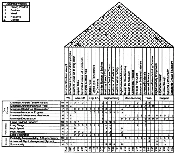
2.2.4 QFD analysis
Quality Functional Deployment (QFD) is a technique used to assign weightings to technical requirements based on their relative importance in meeting customer needs. A QFD requirements matrix, or "House of Quality" is developed in order that a quantitative value may be computed for each design parameter. Figure 2.4 illustrates the concept.
Need Importance Weighting (rypicalty 1- 10) Identdiies Rqmt. Correlation Cofic"s Matrix
Technical use Corp. (Engrg.) Technical Language Requirements How, iecn. Rqmt. Priorities Benchmarking Assessment of Engineering Competitive Capabilities Fimlre 2.4: OFD Benchmarking Assessment of Customer Views about Competitor Capabilities Quantification of - Tech. Rqmts "How Much?" Tech. or Regulated Constraints / Considerations concent (Ref.
61
Customer Relationship Needs MatrixUse Determines Tech.
Customers Rqmts. Priorities Using Words Need Importance
Weightings
'Whats'
. .. . . "m[~ . . . .. . r - | -- -'T'- - - =
L-Technical requirements are compared against customer needs. The relationship matrix, like the DOC relationship matrix in Figure 2.3, assigns weighting terms to technical requirements based on the degree of influence each requirement has in terms of meeting a particular customer need. Several different weighting schemes are available. In this particular design, traditional practice was altered and penalties were assigned for negative effects. It was the author's decision that this method would produce more realistic results. Weighting numbers in the relationship matrix are multiplied by the customer need importance weightings in order to arrive at technical requirement priorities. The "roof' on the house is a correlation matrix which identifies those technical requirements that conflict with others. For example, if "minimizing structural weight" and "increasing aspect ratio" were two design goals, achieving one would make the other one harder to achieve. This conflict would be noted in the correlation matrix. Such conflicts are used to identify where design trade studies should be performed. For this design the perimeter comment regions are not used. A detailed description of the QFD process is given by Ref. 6.
The QFD build for the NSA wing design is shown by Figure 2.5. For clarity, technical requirements were subdivided into seven categories: weight, aerodynamic efficiency, engine efficiency, engine sizing, manufacturing, technology, and support. Also, customer needs were categorized into three types: cost, performance, and support (operational) drivers. From the resultant QFD build, a set of prioritized technical requirements was determined, and is shown in Table 2.4.
2.2.5 Customer Needs Summary
Through breakdown of the ORD, explicit customer needs were obtained. Implicit customer needs were identified based on life cycle cost design drivers. Both explicit and implicit customer needs were then assimilated and prioritized. Technical requirements were identified and prioritized through the QFD process based on their impact on important customer needs.
Quadratic Weights 9 Strong Positive 3 Positive 1 Weak -3 Negative 0 Confhct
Minimize Aircraft Takeoff Weight 10 9 3 3 1 3 1 9 -3 3 3 9 3
Minimze Aircraft Purchase Pnce 10 9 3 9 9 9 9 9 1 -3 -3 9 3 9
Minimize Block Fuel Consumption 7 9 9 9 9 9 3 3 3 - 3
' Minimize Number of Engines 7 9 1 3 3 3 3 9 -3 3 9 9 3
Minimize Maintenance Man Hours 6 3 9 9 1 1 3 3 -3919 99 9 9
MinimizeDepreciation 6 9 9 9 9 3 1 9 1 9 11
Large Payload Capac 10 9 3 1 1 9 9 9 3
Long Range 10319999911 -3 -3 1 3
High Spee 4 -3 1 9 3-3 3 9
High Altitude 4 9 3 3 3
Long Endurance 4 3 1 9 9 9 9 3 1 1 3 -3 -3 3
Rea ,Maintainabli, & Suortabt 10 3 9 9 9 9 9 - 9 9 9 9 9 9
Advanced Flight ManagementSystem 7 9 9 3
Survivabdy 4 3- -3 9 9 9 CY 9 a, 9, 11 1N-3
o rY
N .4 N N N a,
Figure
2.5:
OFD Build.
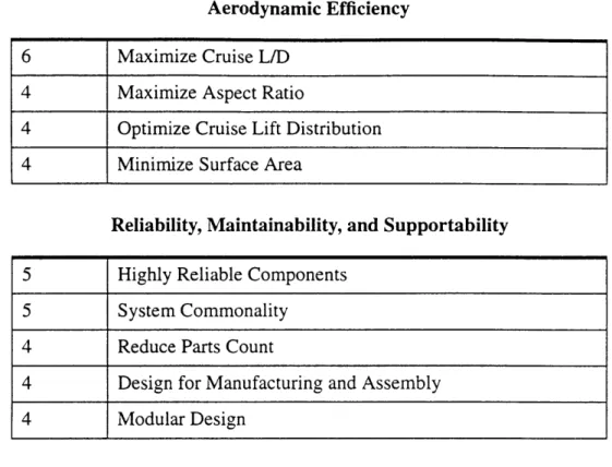
Table 2.4: Prioritized Technical Requirements
Wing Structural Weight
A41 141 LM cc ; C) V (M Fg C M 0 L C E -E t Bd C E Z w 2 2 2-E Hf I~ E E UH E - : Id a L ) = - AO
10 Minimize Structural Weight
6 Reduction in Systems and/or Synergize 6 Maximum Cruise L/D
4 Maximize Aspect Ratio
4 Optimize Cruise Lift Distribution 4 Minimize Surface Area
Aerodynamic Efficiency
6 Maximize Cruise L/D
4 Maximize Aspect Ratio
4 Optimize Cruise Lift Distribution
4 Minimize Surface Area
Reliability, Maintainability, and Supportability
5 Highly Reliable Components
5 System Commonality
4 Reduce Parts Count
4 Design for Manufacturing and Assembly
4 Modular Design
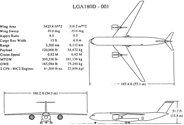
2.3 Baseline Configuration
Figure 2.6 shows a three-view of the Lockheed-provided baseline configuration for the
NSA. The three-view shows planform sizing and engine placement. The same
configuration was used for the baseline wing and all of the flexible variants used in this project.
2.4 Derived Requirements
Beyond customer needs, the ORD was examined for technical flight requirements. Using ORD explicit specifications and empirical practice, a set of derived requirements was obtained for the deployment mission of the NSA. Derived requirements represent the mission profile (used for determining loads), structural arrangement and structural properties (used for sizing of structural elements). These derived requirements, along with
the baseline configuration, are used in the design of a baseline wing for the NSA.
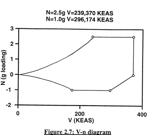
2.4.1 V-n Diagram
The limit loading during flight for a plane in the weight category of NSA is 2.5 g (Ref.
7). Gross takeoff weight is specified as 400,000 lbs. Initial cruise weight is therefore
of 0.82. A V-n diagram was prepared which represents the worst-case combined weight and dynamic pressure flight scenario. The diagram is shown in Figure 2.7. This type of diagram shows the combined velocity and loading conditions that the aircraft is expected to withstand during the worst-case scenario maneuver. However, the V-n diagram resulted from consideration of only one point in the flight envelope, and only 6 loading scenarios out of a possible 38 listed in Ref. 8 were considered.
LGA1 80D
- 0017
Wing Area
Wing Sweep
Aspect Ratio Cargo Box Width Range Payload Cruise Speed MTOW OWE 2 CF6 -80C2 Engines 3425.8 ft**2 35.() deg 9.5 13 ft 3,300 nm 120,000 lb 0.82 M 399,330 lbi 165,984 lb 6 ,500 IIb ea.
Figure 2.6: Baseline Configuration
3 1 8.2 m**2 3.5.0 tleg 9.5 4. min 6,112 km 54,432 kg 0.82 M 181,136 kg 75,290 kg 27,896 kgf -. 187.4 ft (57.1 m) --. _~~s .____N=2.5g V=239,370 KEAS N=1.Og V=296,174 KEAS CD, .-z 200 V (KEAS) Figure 2.7: V-n diagram 400
2.4.2 Wing Structural Arrangement and Material Selection
For this design, a two spar wing was chosen with the front spar placed at 15% of the
chord and the rear spar placed at 65%, measurements taken perpendicular to the mid-point
of the chord. A generic supercritical airfoil was used. Airfoil and spar locations are shown in Figure 2.8.
Rib spacing was usually set at 24 inches. Unless obstructed by a pylon, stringers were spaced every 12 inches starting from the trailing edge of the torque box. Table 2.5 lists the Lockheed-specified wing planform parameters. Aluminum was used for all structural elements in the wing, with Al 2024 used on the bottom surfaces and Al 7075 used for the top surfaces, as is standard practice for aluminum wings.
Table
2.5:
Wing Planform Geometry
2.4.3 Determination of Structural Parameters 2.4.3.1 Reference Frame
Figure 2.9 is a schematic showing the positions of the structural elements which will be referred to throughout this section. The coordinate system used in this design places x
in the axial direction with x = 0 representing the leading edge, y spanwise perpendicular
to x with y = 0 representing the centerpoint in the span of the wing, and z in the vertical
direction with z = 0 representing the bottom of the airfoil.
Span 180.2 feet
C/4 Sweep 35.0 degree
Root chord 29.3 feet
Tip chord 8.8 feet
MAC 20.9
Area 3,425.8 sq feet
AR 9.5
X apex (leading edge junction) 44.9 feet
Y apex (leading edge junction) 0.0 feet
Z apex (leading edge junction) 19.6 feet
X C/4 MAC 44.7% fuselage
length
t/c root 16.3%
Trailing Exterior Landing edge
Center plate gear nboard flap
wing doubler fing Flap vane
jl Spoiler
aileron
Outboard flap S Flap vane
SOutboard aileron
Slat track Front spr Slat track can ar Flap vne
Figure 2.9: Structural Reference Frame (Ref. 8)
2.4.3.2 Calculation of Torsional Rigidity
The torque box includes the area between the forward and rear spars:
Abx = h - x es) c
where Abx is the area of the torque box, hf is the height of the airfoil, xfs represents the
axial location of the front spar (distance of the front spar from the leading edge), Xrs the axial location of the rear spar, and c is the chord length at the particular spanwise location.
From this information, the torsional moment of inertia is given by:
(2.1) 4Ax2 bxr c (Xrs - Xfs) c (X c (xrst- - XfS)fs) t b
where t terms represents thicknesses of the top and bottom skin. Structural property equations used in this section can be found in Ref. 9.
4A2
The shear modulus, G, for Aluminum is 4.0 x 10^6 psi. Torsional rigidity is given by
GJ.
2.4.3.3 Calculation of In-Plane Bending Stiffness
Airfoil height was determined geometrically from the baseline configuration. The airfoil height is given by
h = 0.09c,
f 0.12
t in this case represents airfoil thickness.
Next was the determination of respective areas for the top and bottom of the torque box. These areas are given by
At, b = nstAst + Afs + Ars + ts (Xrs - Xfs) (2.4)
where nst is the number of stringers, Ast is the cross-sectional area of each stringer, As is the cross-sectional area of the front spar cap, Ars is the cross-sectional area of the rear
spar car, ts is the thickness of the skin in question (top and bottom), Xrs is the axial
location of the rear spar, xfs denotes the axial location of the front spar. The z center of mass is given by
Ahf (At + Ab)
where z =0 denotes the bottom of the airfoil (as defined earlier). In-plane moment of inertia is given by
(2.5)
(2.3)
Ixx = At(z - )2 +Ab (zb-) 2= At(hf-2) +Ab (2.6)
The modulus of elasticity, E, is 1.05 x 10^7 psi. In-plane bending stiffness is given by
EIxx
2.4.3.4 Calculation of Out-of-Plane Bending Stiffness
Out-of-plane inertia, Izz , is given by the following relation:
which is approximated by the discrete sum:
Iz = Ax2 - ZA-2 (2.8)
with the x -centroid given by:
- Ax
x= A (2.9)
EA
This discrete approximation was used for the stringers and spar caps. Locations and areas of both the stringers and spar caps are known. For the case of the skin (continuous mass), an exact integral can be computed. This is given by:
x
rs
J(x - ) 2dxdz (tt + tb) (x- ) dx (2.10)
where tt and tb denote the top and bottom skin thicknesses, respectively. This term is
added to the summation for the discrete terms to produce overall zz . Multiplying by E yields the out-of plane bending stiffness, EIZz
2.4.3.5 Determination of Coupling Plane Bending Stiffness
This derivation is similar to that of Ezz . The coupling inertia term, Ix, is given by:
I=-f f (x - ) (z - ) dxdz = -f f (xz- )dxdz (2.11) with a discrete approximation given by:
I z = IA2- lAxz (2.12)
The center of masses, 5i and Z, were determined by the in-plane and out-of-plane stiffness derivations. For the discrete cases of the stringers and the spar caps, lAxz can be determined because the locations of the elements are known. In the case of the skin, the appropriate integral is:
Xr,, X h
I=-J (x-i )((Z- )ttt+ (Z- )btb)dX = -(X (-5)2 2 )dx (2.13)
EIxz is computed from this. 2.4.4 Mass Distribution
For the purposes of this design, the wing empty mass percentage breakdown was set to the following for the baseline case:
Leading Edge Mass = 5% of total Trailing Edge Mass = 35% of total Torque Box Mass = 60% of total
Overall torque box mass was reduced for the more flexible cases, while leading edge and trailing edge masses remained the same. Determination of torque box mass reductions is discussed in Chapter 4.
2.4.4.1 Determination of Leading Edge Mass
The leading edge mass per length for each spanwise location is proportional to chord length and is thus given by the following relation:
0.05cwt
Mie A (2.14)
le Aws
where wt is the total wing mass and Aws is the wing surface area. 2.4.4.2 Determination of Trailing Edge Mass
Similarly, mass of the trailing edge per unit span is:
0.35cwt
Mte A (2.15)
ws 2.4.4.3 Determination of Torque Box Mass
The torque box mass is assumed to be proportional to its EI, with B defined as the constant of proportionality.
mb = BEI (2.16)
Here El is taken to be EIxx , except that all structural elements in the torque box but the
skin are neglected (an assumption that in this application yields a very accurate answer because of the relatively similar spanwise distribution of masses of all of the elements).
EI =2EAs(f (2.17)
xx 2)
mb = gpA12As (2.18)
where As is the area of the skin, hf is the airfoil height, g is acceleration due to gravity,
and PAl is the density of aluminum.
Combining equations 2.16 and 2.17 yields:
EIxx 2
nb = 2gpAl- h- (2.19)
or:
mb = 4gPA1 El2 x (2.20)
where g is the acceleration of gravity and PAl is the density of aluminum. Recalling the equation for hf,
h = 0.09c 1 2
The torque box mass equation can now be presented in terms of already available design parameters:
(0.12 2 gpA/
b 0.09) ct )c2E 2 xx
Equation 2.21 presents a useful relation for determining the effect of chord, thickness
to chord ratio, and EIxx on torque box mass. B therefore can be taken to be proportional
to the term in front of EIxx in equation 2.21. The constant multiplier of B is one which
brings the torque box mass up to 60% of the empty wing weight. In this case, that multiplier is 2.92. So, B is given by:
B 2.92 4 0.122 P(2.22)
0.09 t )2 C2 E
2.4.4.4 Determination of Fuel Mass Distribution
Overall fuel weight included in the wing is 114,931 pounds. Fuel mass per unit span
Mf is given as follows:
Wf 2
(t; wf
M = Ct = C (2.23)
tb C tb
where Vtb is the volume of the torque box, t is the thickness of the airfoil, wf denotes fuel
weight, and c represents the chord.
Fuel is placed out to 85% of the half span. Torque box volume in the equation represents the volume out to 85% of half span. It should also be noted that terms representing fuel weight in the equation are for half of the total fuel mass, because total fuel mass accounts for fuel placed in both halves of the wing.
2.4.4.5 Engine Mass
Each of the CF6-80C2 engines specified for this project weighs 15,000 pounds and will be attached with an engine pylon at 411 inches along the half span (Ref. 10). The offset between the engine center of mass and the pylon is -198.80 inches along the chord,
-93.03 inches along the span, and -80.945 inches normal to the wing. The reader can refer
to Figure 2.6 for a visual representation of engine placement. Engines act as point masses at their points of attachment.
2.4.5 Other Parameters
Center of gravity along the chord is calculated by assuming center of masses for each of the contributions to mass:
X
cg = 0.4Mf+ 0.382BEI + 0.075Me + 0.0825M (2.24)
C f xx le te
Zero load values of x and z due to sweep and dihedral respectively were obtained from the baseline configuration geometry. Also specified by the baseline configuration are built-in twist, zero degree angle-of-attack, and the placement of the ailerons along with their effects on lift and moment per degree deflection.
2.5 Functional Analysis
2.5.1 OverviewThe objective of functional design is to facilitate the design, definition, and development process. Functional analysis is a systematic approach for translating system technical requirements into specific qualitative and quantitative design requirements. Within the context of functional analysis is a tool known as a functional flow diagram. A functional flow diagram is a pictorial scheme used as a mechanism for portraying system functional requirements, illustrating series and parallel relationships, and establishing a hierarchy of system functions.
2.5.2 Functional Flow Diagram
For the purposes of this design, a functional flow was created in order to identify potential design variants. The top-level functional flow diagram is shown in Figure 2.10.
Level 3 (operational)
-I
etc.
Level 4 (functional)
I Provide RangeLevel 5 (requirements)
2.5.3 Design Variants
The following possible design variants were identified:
* structural material for the wing can be either metal, composite, or a hybrid combination of the two
* size of control effectors can be changed and they can be placed at both the front and back of the wing planform
* conventional and AFW technologies could be mixed by changing the degree of wing
flexibility
* the high-lift system can be broken up into multiple parts to accommodate bending
Because only one design iteration is used for this project, wing flexibility is the only design variant examined. The remainder are left for future AFW research.
2.6 Physical Design Questions
In order to better satisfy the functions and requirements of the NSA using AFW technology, a set of physical design questions was developed:
Wing Structural Weight
* What is the desired material selection: metals/composites? Can the tailorability of
composites be beneficial in an AFW?
* What are the potential weight savings with an AFW for a high aspect ratio wing? * What are the potential penalties for systems integration and complexity?
Aerodynamic Efficiency, Flight Controls, and High Lift
* How does use of an AFW affect load alleviation? * Can control surface reversal be exploited?
* How does use of an AFW affect elastic mode control? * How is high-lift integration affected by an AFW?
Reliability, Maintainability, and Supportability
* What are the reliability, maintainability, and supportability issues that may affect the implementation of AFW technology?
This project examines the issues of weight savings, aerodynamic efficiency, and controllability. Remaining issues are left for future study.
Chapter 3
Design Process and Computer Tools
3.1 Design Process Overview
Having determined requirements for the NSA, a design process was formulated to translate these requirements into a baseline wing design. Figure 3.1 shows a schematic of the wing design process used in this project. As discussed in Chapter 2, aircraft geometry was the starting point of the design process. From this, and from empirical data, a wing structural arrangement was determined. This wing structural arrangement along with planform and control surface layout was input into a computer tool known as ACAD (Advanced Computer Aided Design), chosen because of its excellent drawing and geometric analysis capabilities. ACAD produced the wing geometry used in this project. The program is also a preprocessor for ASTROS (Automated Structural Optimization System). ASTROS was chosen for use in the project because of its overall excellent interdisciplinary analysis of wings. ASTROS took as an input a finite element model determined from ACAD geometry. It then performed an air loads analysis, a sensitivity
analysis, and a structural analysis. Structural analysis. Structural analysis was performed using the finite
element model and the determined loadings. Geometry from ACAD along with flight conditions was also input into ASWING, a multi-discipline design tool which uses lifting line theory to predict airloads and nonlinear beam theory to predict structural loads. Sizing of structural elements was input into ASWING from ASTROS. ASWING and ASTROS were also used to validate each other's structural and aerodynamic predictions. The capacity for ASWING to quickly incorporate changes in wing structure led to its being chosen for use in sensitivity analysis, while ASTROS was used to produce a high-fidelity
model of the wing structural weight.
3.2 ACAD Description
ACAD is the primary computer tool used by Lockheed Fort Worth Company's Advanced Programs for configuration design of aircraft, both new and existing. The program was initially developed starting in 1982 by the Design Methods Group, a section
of Advanced Programs, with the main goal being to facilitate the preliminary design process by eliminating drawing boards and reducing design iteration time. The program's main role is the generation of geometry; however it does perform limited analysis. Wireframes, surfaces, and solids can be used to model geometry in both two and three dimensions. Geometry can then be downloaded into a postscript file, and hardcopy outputs can be obtained. A full description of ACAD is given by Ref. 11. For discussion of the use of ACAD in this project refer to Ref. 12.
ASWING g o ASWING
Aero/Stuct Analysis Sensitivity Data
Planform and Control Surface Layout M
ACAD
Structural
ASTROS Weigh
AAutomated Structural
FEM Model Optimization System
Figure 3.1: Wing Design Process Elements
3.3 ASTROS Description
ASTROS is a broad-based, multidisciplinary computer tool used for the analysis of wings and the interactions between structures, aerodynamics, and control systems within the wing. There are six major functions performed by ASTROS: design optimization, sensitivity analysis, structural analysis, air loads analysis, aeroelastic analysis, and control response. Design optimization is accomplished using the Automated Design Synthesis procedure. The program searches for the lowest weight design possible that satisfies specified structural and aerodynamic constraints. Sensitivity analysis involves the calculation of analytic derivatives for response methods in order to determine the effects of varying parameters and constraints. Structural response is determined by finite element
analysis, with response gauged in terms of stresses, strains, strain energies, natural frequencies, and displacements. Air loads analysis is performed based on a panelling method known as USSAERO-C, with minor modifications. Aero loads are coupled with structural loads. Aeroelastic analysis is based on flutter calculations. ASTROS also analyzes the interactions between a control system and the wing structure in order to determine structural response and control effectiveness. A full description of ASTROS is given by Ref. 13. For discussion of the use of ASTROS in this project, refer to Ref. 12.
3.4 ASWING Description
ASWING was developed by Mark Drela at MIT as a tool to perform structural and aerodynamic analysis of flexible high-aspect ratio wings. Initially, the program was used for modelling of the small human-powered plane Daedalus, but was modified to account for arbitrary sweep angle to allow for use on the wings in this project. Nonlinear beam theory is used for the structural model, with up-down, fore-aft, and torsional deflections allowed. No limit is placed on the magnitude of these deflections. Prandtl lifting-line theory is used for the aerodynamic model, applied to the deflected wing geometry. Hence, the structural and aerodynamic models are fully coupled. A complete description is included in Ref. 14.
3.5
ASWING Input File
In order to determine the values of variables in the input file, a MATLAB script was written which computed the necessary structural and aerodynamic parameters from
structural element sizing and the assumed wing planform. This input file is located in Appendix C. Structural element sizing for the ASWING build was based primarily on ASTROS results. In the ASWING case, unlike ASTROS, the sizing distribution is assumed to be linear from root to tip. Structural parameters were calculated at spanwise locations corresponding to termination of stringers, flaps, engine pylons, and the end of the fuel tank.
3.6 Sensitivity Analysis Using ASWING
Parameters considered in the sensitivity analysis were ratio of torque box mass to that
of the baseline wing torque box mass (baseline wing torque box mass given by ASTROS sizings and used in the ASWING input file), tip washin angle, and flight load factor. These parameters were analyzed to determine effects on spanwise efficiency, aileron reversal speed, maximum spanwise strain, and maximum spanwise shear. The parameters specified in Table 3.1 were kept constant throughout the analysis.
Table 3.1: Constant Flight Conditions in ASWING Analysis
Flight Conditions
Gross weight = 380,000 lbs
Altitude = 32,000 ft.
Flight Mach number = 0.82
ASWING allows for direct linear scaling of any or all input file parameters, with the values affected at all spanwise locations. This feature was used in the analysis as the torque box weight was altered. As described earlier, the weight of the torque box is assumed to scale directly with all of the bending stiffnesses and torsional rigidity.
3.7 Risk Management
Because an AFW had never before been examined using any of these programs, the project was structured to avoid dependency on any one of these codes alone. ACAD geometry was not affected by the AFW alterations, because it was only used for drawing the baseline configuration. If the program had failed, Lockheed-provided planform parameters and a sketch of the baseline wing would have been used for estimates of the wing geometry that would have been input into ASTROS and ASWING. The sensitivity analysis of ASWING could have been performed by ASTROS, although it would have been a much more time-consuming endeavor. Similarly, if ASTROS had not been able to output structural data, a spreadsheet analysis would have been used for the task, although with much less fidelity.
Chapter 4
Results
4.1 Overview
As specified in Chapter 3, both the baseline wing and the flexible wing variants were analyzed using computer codes ASTROS and ASWING. ASTROS provided sizing of structural components and deflections under design-intended flight conditions. ASWING was used to "fly" the airplane through different points on the V-n diagram and determine deflections, stresses, strains, reversal speeds and span efficiency. Because of the versatility of ASWING, the program was used to perform comparisons between the baseline and more flexible wings, as well as to determine the effect of washin on the wing.
4.2 Wing Sizing Results
Inputs into ASTROS were the NSA baseline configuration provided by Lockheed, the structural layout as specified in Chapter 2, and the V-n diagram for the intended military deployment mission. ASTROS produced sizing distributions of structural elements along the span, as well as deflections under the loading conditions encountered during the mission. These sizings were incorporated into the baseline wing. For the baseline wing, a conservative yield criteria was used for sizing, such that the wing could be made more flexible. The effects of increased flexibility were examined in the sensitivity analysis. Stringers were not included in the ASTROS model, but are included in the ASWING analysis. This difference was due to the complexity of entering stringers into ASTROS. Table 4.1 shows the root and tip sizings of structural elements for the ASWING build. A more complete discussion of the use of ASTROS in this project as well as the elemental sizing results throughout the span can be found in Ref. 12.
4.3 ASWING validation of ASTROS deflection results
ASWING computed results for several flight conditions, and wing deflections were
compared with those determined by ASTROS for the same conditions. The results compared favorably. To quantify this result, for Mach 0.69, equivalent airspeed 239 knots,
and 2.5 g of loading, ASTROS tip deflection was 16.9 feet and ASWING tip deflection was 17.6 feet, a difference of less than 5%.
Table 4.1: ASWING Structural Element Sizing
Structural Element Root Tip
Top forward spar (in^2) 16.0 0.5
Top aft spar (in^2) 15.0 0.5
Bottom forward spar (in^2) 17.0 0.5
Bottom aft spar (in^2) 50.0 0.5
Top skin thickness (in) 0.50 0.05
Bottom skin thickness (in) 0.50 0.05
Stringers on top (in^2) 1.06 0.53
Stringers on bottom (in^2) 0.86 0.43
4.4 Effect of Flexibility on Wing Weight
For the purposes of this study, a parameter K was created and defined to be the ratio of the torque box weight of the wing in question to the torque box weight of the baseline wing. Thus, K = 1 for the baseline wing. Change of overall structural weight due to change in K, denoted by AK, is given by:
AW ( Wbx N1AK = 0.60AK (4.1)
W = Wle + Wte + Wbx
where W is the wing structural weight, the w terms represent respective weights listed as
follows: wle is the leading edge weight, wte stands for the trailing edge weight, wbx is the weight of the torque box of the baseline wing. It should be noted again that the above equation represents a simplification used here solely to illustrate trends. If a full wing with
K < 1 was designed, the actual wing structural weight would be determined by an
4.5
Aileron Control Effectiveness
Roll rates for 1-g maneuvers were examined as a function of equivalent airspeed for both the baseline torque box K= 1 and a torque box that was reduced to 60% (K=0.60) of its original mass (24% lower wing structural weight). Factoring in the wing structural
weight to the weight of the aircraft, the K = 0.60 torque box leads to a 3.2% uniterated
gross takeoff weight as compared to the baseline torque box case. Uniterated weight means that no further design cycles were performed to scale down the entire configuration in response to this component weight reduction. In actuality, gross takeoff weight savings would be greater. Figure 4.1 is a graph of roll rates for the two cases versus flight velocity with a five degree aileron deflection.
d I K=1.00
3 2
K=0.60
0 0 It 150 a 1 230 :W 350 4W 450
Equivalcnt Airpccd. V. KEAS
Figure 4.1: Aileron Control Effectiveness
For a completely rigid wing, steady state roll rate is a linearly increasing function of airspeed. Flexibility has a continually greater effect in reducing aileron effectiveness as dynamic pressure is increased.
Control effectiveness can be quantified by the parameter -,.which is the roll rate for
r
an aileron deflection relative to what it would be for a rigid wing. From Figure 4.1, one can see the drop-off in control effectiveness from a rigid wing as compared to a flexible
wing. A lower value of - means that either a larger aileron deflection or a bigger aileron
r
surface is required to produce the design roll rate. There is a physical limit to aileron deflection and sizing, which could place a restriction on use of conventional controls on flexible wings. A more in-depth analysis, which would examine structural effects of large
aileron deflections and sizings, would be needed to determine whether this reduction in control effectiveness is a significant design problem. If desired roll rate could not be achieved by a flexible wing, a conventional high speed inboard aileron (see Figure 2.10) could be designed that would be used when the outboard aileron loses effectiveness. It
should also be noted that for both torque box masses, the value of nf is equal to
r
approximately 0.70 at the point where roll rate begins to drop.
Reversal speed (the velocity at which roll rate is zero) decreases with increasing wing
flexibility (about 25% lower for K = 0.60 as compared to K = 1. As can be seen from
Figure 4.1, reversal velocity occurs at 430 knots equivalent airspeed (KEAS) for the reduced weight torque box case. Therefore, the issue of aileron reversal is not a factor for this design, and conventional control surfaces can be used. Production of a design which would include reversal phenomena would likely involve having more than two spars and/ or different material selection (Ref. 15).
4.6 Maximum Strain
Maximum strain (highest value of strain at any spanwise location) is important structurally in a wing design because often a wing is sized by its yield point, meaning structure is designed such that at worst expected case scenarios for dynamic pressure during flight, the wing would be on the verge of yielding. Figure 4.2 shows the predicted
effect of washin angle t and stiffness (torque box mass) on maximum strain:
.007
.001
S 1.25 1.5 1.7 2 2.25
Lod Factor, N (-)
Figure 4.2: Maximum Strain
t=+4 t=+O t=+4 t=+O 1 K=0.60 K=1.00
2-Stiffness, as expected, has a significant effect on maximum strain. This is because bending and torsional stiffness parameters, El and GJ respectively, are strong drivers of strain calculations. In this case, a 40% reduction in torque box weight leads to about a 45% increase in strain, with the percentage increase being approximately the same over several load factors. Washin angle, on the other hand, has an effect of only about 6.5% effect on strain for the 4 degree change that is examined here. In the reduced torque box case, the value of maximum strain approaches 0.006 (aluminum's yield value) as the design load of 2.5 g is approached. This does not imply that the torque box weight could not be reduced any further because different sizing distributions of structural elements would yield different strain results. However, the sharp increase in strain due to flexibility represents an important factor in a flexible design. One possible result of this is that stiffer materials will tend to be chosen for flexible wings.
4.7 Maximum Shear Stress
As with strain, shear stress was calculated as a function of washin angle t and torque
box stiffness. Results are summarized in Figure 4.3.
1.03 K=1.00 .... K=0.60 ,--'"° ° t=+4 0.9 0.8 0.75 . 0.7 0.65 1.25 1.5 1 75 2 2.25 2.5 Load Factor, N (-)
Figure 4.3: Maximum Shear Stress
In the shear stress case, it is not stiffness but rather washin angle which has the strongest influence, causing a dramatic increase in shear stress. This is due to the effect of washin in moving the centroid of the half span lift further outboard, thereby creating a
more elliptical lift curve distribution. Figure 4.4 shows lift distributions along the K = 1 wing at cruise without washin and with 4 degrees of washin. The dotted line represents no washin, whereas the solid line represents a washin of 4 degrees.
0 .8 . .... . .
0.8 .... ...
0.0
Figure
4.4:
Lift Distributions with and without washin
Although the absolute values of shear stress indicated in this analysis do not reach the structural limiting value for aluminum, the trend of increased shear with washin angle is important because it may place a limit on the amount of washin angle in a design.
4.8 Span Efficiency
For the purposes of this analysis, span efficiency e is taken to be
S C2
o L
- e (4.2)
brb DI
0
where b0 represents the zero-load span, S the zero-load wing surface area, C is the
square of the lift coefficient, CDi is induced drag. The zero-load span is used so that e is
strictly a measure of CDi relative to C . If the loaded span was used instead of bo, the
interpretation of e would be less clear. Figure 4.5 shows the effect of weight reduction and