Adaptive Mechanisms for Self-Aware Multicore
Systems
byEric Lau
B. A. Sc., University of Toronto (2010) M ASACHET 2NSITUTE)C 92
Submitted to the Department of Electrical Engineering and Computer Science in partial fulfillment of the requirements for the degree of
Master of Science
at theMASSACHUSETTS INSTITUTE OF TECHNOLOGY
September 2012
@
Massachusetts Institute of Technology, MMXII. All rights reserved.Anthor
Department of Electrical Engineering and Computer Science
August 13, 2012 Certified by
Srini Devadas Professor of Electrical Engineering and Computer Science hesis Supervisor
Certified by
Accepted by
Anant Agarwal Professor of Electrical Engineering and Computer Science Thesis Supervisor
L& AUKolodziejski Chairman, Department Committee on Graduate Students
Adaptive Mechanisms for Self-Aware Multicore Systems by
Eric Lau
Submitted to the Department of Electrical Engineering and Computer Science on August 13, 2012, in partial fulfillment of the
requirements for the degree of Master of Science
Abstract
As the push for extreme scale performance continues to make computer architectures in-creasingly complex, there has been a call for better programming models, and the systems to support them. Todays microprocessors now expose more system resources than ever to software, leaving it up to the application programmer to manage them. Studies have shown that the energy efficiency of future technologies may eventually affect the ultimate perfor-mance of multicore processors, and so programmers are forced to optimize systems for both performance and energy in the midst of countless configurable parameters - an extremely difficult task.
Self-aware systems can configure themselves through introspection, providing perfor-mance and energy optimization without pressing an unrealistic burden on the programmer. However, to build effective self-aware systems, we must identify useful sources of adaptivity. This thesis will show the effectiveness of a number of adaptive mechanisms for self-aware multicore systems. We show that adding these mechanisms improves efficiency, and then make a case for coordinated adaptive systems. Coordinated systems treat adaptivity as a first-class object, and can outperform all non-adaptive, statically configured, and uncoordi-nated adaptive systems that do not possess a general view of system-wide adaptivity.
Thesis Supervisor: Srini Devadas
Title: Professor of Electrical Engineering and Computer Science
Thesis Supervisor: Anant Agarwal
Acknowledgements
How do you write something like this without loads of help?
You don't. At least, if there is a way I don't know it, because I have a lot of thank you's to distribute.
First, I would like to thank Anant Agarwal for taking me into his group, and giving me a chance to work here at MIT. However much has changed as I've grown up, coming to MIT has ever been a dream of mine. His passion and leadership have been a constant motivation, and his ideas were invaluable to this work.
Thank you to Srini Devadas, who took me under his wing after my first year. It was almost by chance that we pinballed into his group, but he welcomed us with open arms anyway, and provided me with inestimable wisdom and guidance.
To Jason Miller and Hank Hoffmann, who would have been listed as co-advisors if they would let me. Thanks for being consummate leaders and teachers, and being two of the smartest people I have ever met. It still has not ceased to amaze me how much these guys know, and on what seem like virtually every existing topic. For better or for worse, I've never felt more incompetent than when I am with them. I'm not even sure they realize this, but without them this thesis would probably have no content at all.
Thanks to George Kurian, who helped me solve almost every Graphite issue I had to misfortune of facing, which is saying something because almost all of my work has been on Graphite. Also thanks for being an awesome programmer. I always felt a happy sense of security when I knew he was helping out on anything, for it was basically a guarantee that it would be working at the end of it.
Thank you to the test chip family: Sabrina, Yildiz, and Mahmut. We hit some snags and a couple of false starts, but we made it. Now on to newer and better chips! And to the Carbon Group, you guys are awesome. I've worked in a lot of research groups in my academic career, but this group has been by far the smartest and most awesome. I realize I have used the word awesome twice, but really it is the only word that is appropriate here. On the flip side, my family and friends will always be the reason I do any work whatsoever. The past couple years have been tough, even by my dismal standards, but somehow you all got me through it again. I will not use names, but all of you know how important you are to me.
1 Introduction
1.1 Motivation . . . . 1.2 Previous Work . . . . 1.2.1 Self-Aware Systems . . . . 1.2.2 SEEC (SElf-awarE Computing) Framework .
1.3 Thesis Scope . . . .
2 Self-Aware Systems
2.1 Overview . . . . 2.1.1 Multicore Scaling and Limitations . . . . 2.1.2 Observation-Decision-Action Loops . . . . 2.2 Uncoordinated Adaptive Systems . . . . 2.3 SEEC Framework . . . . 2.3.1 Observation . . . . 2.3.2 Decision . . . . 2.3.3 A ction . . . .
3 Angstrom: A Massively Multicore Self-Aware System 3.1 Architecture Overview . . . . 3.2 Observation . . . . 3.2.1 Performance Monitoring . . . . 3.2.2 Energy Monitoring . . . . 3.3 D ecision . . . . 3.4 A ction . . . .
4 Knobs for Self-Aware Multicore Systems
4.1 Caches Associativity and Size . . . .
-6-12 12 14 14 15 16 18 . . . . 18 . . . . 19 . . . . 21 . . . . 23 . . . . 26 . . . . 27 . . . . 28 . . . . 29 31 . . . . 31 . . . . 33 . . . . 33 . . . . 36 . . . . 38 . . . . 40 43 43
4.1.1 Motivation ... 4.1.2 Tradeoffs . . . . 4.1.3 Implementation . . . . 4.2 Core Allocation . . . . 4.2.1 Motivation . . . . 4.2.2 Tradeoffs . . . . 4.2.3 Implementation . . . . 4.3 Domain-Specific Dynamic Voltage and Frequency Scaling (DVFS)
4.3.1 Motivation . . . . 4.3.2 Tradeoffs . . . . 4.3.3 Implementation . . . . 5 Experimental Evaluation 5.1 Methodology . . . . 5.1.1 Graphite Simulator . . . 5.1.2 Benchmarks . . . . 5.2 Results . . . . 5.2.1 Setting Goals . . . . 5.2.2 Static Oracle . . . . 5.2.3 SEEC Results . . . . 5.3 Discussion . . . .
6 Conclusions and Future Work 6.1 Contributions . . . . 6.2 Future Work . . . . 6.2.1 Partner Cores . . . . 6.2.2 Application Classifier . 6.2.3 Extra Knobs . . . . Bibliography Contents 43 44 48 59 59 59 62 63 63 64 65 67 67 67 69 70 70 71 73 76 82 82 84 84 85 87 90
. . . .
. . . .
2.1 Normalized energy efficiency results for
ift
using different L2 caches, divided across phases. The target architecture has 64 cores and an 8KB Li Cache. 20 2.2 Graphical representation of an Observe-Decide-Act loop in a self-awaresys-tem . .... . . . .. . . . . 21 2.3 Adaptive microarchitecture in [1]. The shaded components are designed
for adaptivity, and each adapt to application demands through independent ODA loops. Observations are made by built-in performance counters, and decisions are made by events triggered by the counters. . . . . 23 2.4 Intel Turboboost ODA loop. Core frequencies are determined by a global
controller that makes decisions using observations on all cores in the system. 24 2.5 Normalized efficiency of barnes. The Pareto frontier is shown as the blue
connected line. . . . . 26 2.6 The SEEC model. . . . . 27
3.1 The Angstrom architecture. . . . . 32 3.2 Performance counters are memory mapped, access is made through regular
load/store instructions. . . . . 35 3.3 Event probes allow observation of rare events without polling from software. 35 3.4 Breakdown of cache and core component energy between phases in the
ift
benchm ark. . . . . 37 3.5 Block diagram of energy monitor circuit. . . . . 38 3.6 Architecture of a single tile in the Angstrom architecture, showing the main
and partner cores. . . . . 41
4.1 Miss rate vs. cache size and associativity for the SPLASH2 benchmarks, taken from [2]. . . . . 45 4.2 Cache bank organization with surrounding control and sense logic. . . . . . 49 4.3 A 4-way associative cache converted to a 2-way associative cache. A write
access intended for Way 3 is decoded to Way 1 due to the new associativity. 51 4.4 A 4-way associative cache converted to 2-way associativity. The power signals
for each bank are delivered from an encoder that converts the value stored in the associativity status register. . . . . 52
-8-List of Figures
4.5 A 4-way associative cache where half the number of sets is powered down.
Set adaptivity is achieved by turning off constituent blocks in a bank. . . . 53
4.6 Address mapping for static and adaptive caches. The number set index bits changes with the set adaptivity knob, but the number of tag bits stays the sam e. . . . . 54 4.7 An address is that is mapped to the bottom half of the cache is re-mapped
to the top half when the set configuration is adjusted. . . . . 55
4.8 Illustration of the aliasing problem in the set associativity knob. . . . . 56
4.9 Memory hierarchy showing private L1/L2 caches, and a distributed directory. 57 4.10 Illustration of the coherency problem if the cache knobs are implemented for
the L2-cache. ... ... 58
4.11 Unbalanced workloads in Matrix Multiplication: both distributions (a) and
(b) execute with the same latency because block D is a bottleneck, so
distri-bution (b) is much more energy efficient. . . . . 61
4.12 To adapt the core allocation knob, SEEC sets the affinity mask of each thread to correspond to the desired configuration. . . . . 63
5.1 An application is simulated on a self-aware multicore system using Applica-tion Heartbeats, SEEC, and Graphite. . . . . 68 5.2 Results comparing static oracle configurations against an optimal non-adaptive
system . . . . . 74
5.3 Energy efficiency of the best knob combination in each knob class when tar-geted to one-quarter maximum performance. Results are normalized against the non-adaptive, fully-loaded system; actual knob combinations are shown in Table 5.7. . . . . 76 5.4 Contrasting performance and energy behavior of barnes and radix. barness
completion time scales with the number of cores, but radix does not. . . . 78 5.5 The convergence behavior of the knob combination in each knob class with
the largest configuration space for volrend. . . . . 80
6.1 Histograms comparing behavior of compute- and memory-bound applica-tions. Well-defined peaks allow classifiers to make accurate predicapplica-tions. . . 87
Roles and responsibilities in the SEEC model. . . . . Example action model for core allocation knob. . . . .
3.1 Characteristics of SEEC decision engine placement. . . . .
4.1 Miss behavior and causes. . . . .
5.1 5.2 5.3 5.4 5.5
Application parameters for benchmarks. . . . . Simulation settings for fully-loaded system. . . . . Possible knob configurations. . . . . Optimal non-adaptive configuration over all benchmarks. Static oracle configurations for all benchmarks. . . . . .
5.6 Top five knob combinations as ranked by average Heart Rate/W. Values are normalized to the non-adaptive configuration. . . . . 5.7 Best knob combinations for each knob class. The efficiency of each combina-tion is shown in Figure 5.3 . . . .
- 10 -2.1 2.2 26 30 39 47 70 71 . . . . . 72 . . . . . 72 . . . . . 73 75 77
Introduction
1.1
Motivation
As we continue to push the limits of microprocessor technology, the diminishing returns of transistor scaling have made it increasingly difficult to maintain performance gains. In response, architects have shifted their approach to multicore architectures, where several cores on a chip can provide speedup by exploiting application parallelism. Systems with as many as 64 cores have already been fabricated and tested [3], and at the current scaling pace our systems will contain 1000s of cores within the next decade [4].
The development of these systems introduces a critical problem for architects. As transistor technology continues to scale, the number of transistors on a chip increases ex-ponentially. Historically, this has been a boon for architects, whom have happily benefited from the extra budget for logic. However, while scaling does allow us to fit more transistors per unit area - which, to be sure, allows for the development of 1000-core chips in the first place - it also increases the power density across the chip. In fact, if every transistor in
-1.1 Motivation
a 1000-core chip were to be active simultaneously, it would threaten to melt the silicon substrate itself.
The dark silicon challenge describes the phenomenon where, regardless of chip or-ganization and topology, power dissipation constraints will limit the number of transistors that can be active at one time [5]. As a result, much of the chip must be powered off, and is unable to do any useful work; hence the term dark silicon. For architects, this means that energy efficiency is no longer a secondary design constraint that is only relevant for mobile and low-power devices. For future technologies, minimizing energy consumption actually allows for more transistors to be powered on, directly affecting the ultimate goal of performance.
Unfortunately, developing efficient, low-power architectures is non-trivial, and even with a working architecture, it is unrealistic to assume that it would be optimal for every possible application type. Traditionally, the job of configuring a system to optimize the competing goals of high-performance and low-energy consumption has been left to the application developer. This is usually done by extensively profiling the application on different configurations, and identifying the optimal resource distribution over the target architecture. This not only requires the expertise in the application domain, but also a deep understanding of the performance and power characteristics in the system. With the added complexity of varying application workloads, unreliable components, and the sheer number of configurable parameters in modern and future systems, this task is essentially impossible for a massively multicore processor.
One vision for addressing these challenges is embodied by self-aware systems (also known as autonomic, adaptive, self-optimizing systems etc.). These type of systems au-tomatically observes its own state, and optimize performance and energy efficiency by adaptively changing the configuration of the system in real time. In this way, the sys-tem is automatically optimized as the application runs, relieving the burdensome task of
optimization from the programmer.
Furthermore, while exposing large amounts of configurability to the application de-veloper can be counter-productive, a self-aware system lets the system expose as much of the hardware as necessary. Where a programmer would be overwhelmed by the sheer number of configuration parameters, an intelligent software-based management system can utilize all the extra parameters to make well-informed decisions.
With this new way of managing configurability, self-aware systems give rise to an opportunity for implementing large amounts of adaptivity in both software and hardware. There has already been some work in the development of adaptive mechanisms, but most were closed systems that optimized a single component: very few studies investigated inte-grated systems utilizing several adaptive mechanisms. In addition, there has been almost no work on the effectiveness of adaptive mechanisms in massively multicore core systems. As technology scales ever further, the knowledge of which mechanisms perform the best is extremely valuable.
1.2
Previous Work
1.2.1 Self-Aware Systems
Self-aware systems dynamically adapt the behavior of system without human guidance [6,7]. These can be implemented in hardware, as Bitirgen et al. showed by implementing a decision engine using a set of fixed-point multipliers, and observing performance traces to change underlying hardware components [8]; or in software, as the ControlWare runtime observes latency feedback and dynamically partitions web server bandwidth across threads [9]. Many systems in both hardware and software have been implemented and evaluated [7,10,111.
-1.2 Previous Work
Depending on the system, the mechanisms used to enable self-awareness vary widely. In [8], the authors dynamically configured L2-cache sharing, memory bandwidth, and the total power budget for a chip multiprocessor. In another study, the authors in [1] focused on microarchitectural components such as adaptive issue queues load/store queues, reorder buffer, etc., and in yet another project the focus was solely on dynamically reconfigurable caches [12].
A common criticism of this work is that these approaches are limited to an inflexible
set of adaptivity. Once these systems are built, it is very difficult to add or remove levels of adaptivity. Furthermore, the systems that are responsible for actuating the adaptivity are closed to a single level of the compute stack. For example, the engine in [8] implements a hardware-based neural network that configures the adaptive mechanisms through hardwired connections. The neural network has no knowledge of other parts of the compute stack -such as application-level algorithms or OS-level mechanisms - even though the decisions made by the neural network will likely affect the performance of components across compute stack boundaries. Without consolidating observations from all levels, it is improbable that such a system would converge to a global optimum.
1.2.2 SEEC (SElf-awarE Computing) Framework
The SEEC framework developed by Hoffmann et al. allows the consolidation of all adapta-tions in the form of goals, and allows adaptaadapta-tions to be made simultaneously at both the hardware- and OS-level [13]. For SEEC, there is no distinction between types of adaptivity, as long as the appropriate developer registers it into SEEC. For example, an OS-level mech-anism such as the total cores allocated to an application would be registered by the systems programmer, whereas an application-level mechanism such as algorithm choice would be registered by the application developer. SEEC only requires knowledge that the adaptivity exists, and an associated function stub to effect the change.
We will describe SEEC in detail in Section 2.3, but we point out now that while SEEC dissolves the barriers between adaptivity at separate levels, there has been little work studying such a framework with specific adaptive mechanisms, especially on future massively multicore processors. While SEEC indeed possesses the advantage of being able to adapt across computing boundaries, it also takes on the burden of managing exponentially more adaptivity. In this thesis, we will study the performance of SEEC on future multicore systems, and show precisely the adaptations that benefit SEEC the most.
1.3
Thesis Scope
This thesis will explore adaptive mechanisms, or knobs, that provide useful adaptivity for future massively multicore self-aware systems. To measure the effectiveness of these knobs, we will investigate the implementation details of the SEEC (SElf-awarE Computational) framework using the distributed multicore simulator Graphite [14].
Our main metric for evaluation is the energy efficiency of a system, or the perfor-mance per watt, because as discussed future architectures bring the issue of energy con-sumption into the foreground. Designing an optimal architecture has always been difficult, because the resource demands of different applications can be exceedingly dissimilar. To make matters worse, the traditional approach of over-provisioning functionality to protect against the risk of underperformance is no longer realistic, because the threat of dark silicon makes the waste of energy intolerable. Architects have since allowed parts of the system to be configurable, and exposed the knobs to the application programmer so that the optimal architecture can be configured after fabrication. Unfortunately, even if an optimal system configuration existed, identifying it is a task that takes extreme amounts of time and effort, especially as the number of cores continues to scale.
Self-aware systems dynamically configure themselves on-the-fly, and rely on a runtime
-1.3 Thesis Scope
controller to determine the optimal configuration. In this way, there is no tedious process of statically configuring a system, and even an initially over-provisioned system can be made to adapt to the application at hand. Self-aware systems have been an active research topic in the past decade, but with that said, the uncertainty in future computer architecture has left gaps where little work has been done. To wit, even with the failure of Dennard's scaling and the advent of core scaling, there has been little work on adaptivity on massively multicore architectures.
One key challenge is determining whether or not a knob is actually suited for a massively multicore system, because the large number of variables makes this result non-trivial. Therefore, in this thesis, we will focus on potential knobs for self-aware systems, and show results on their effectiveness on a massively multicore architecture.
For this work, we will be using the SEEC framework to enable self-awareness, but we note that many of the points we show will hold true for any aware controller. Any self-aware system that provides goal-oriented programming will allow the developer to specify goals instead of configuration parameters, and the otherwise tedious process of system optimization is abstracted away.
This thesis is organized as follows. Chapter 2 provides essential background on self-aware systems. Chapter 3 describes the architecture of the Angstrom project, especially the features that enable self-awareness. Chapter 4 is the focus of the thesis, where the details of the adaptive mechanisms, or knobs, are thoroughly described. Details on the implementation of the knobs will be included, as will the tradeoffs they provide to a self-aware system. Chapter 5 is the experimental evaluation section. It shows that an adaptive system outperforms a static non-adaptive system, and then evaluates the performance of the knobs when used by a self-aware controller. Chapter 6 will conclude this thesis by summarizing the contributions of this work, and describing future avenues of promising research.
Self-Aware Systems
2.1
Overview
Self-aware systems (sometimes also known as autonomic, adaptive, or self-optimizing) at-tempt to automatically monitor the behavior of a system, and dynamically optimize its own configuration based on runtime conditions. With the unyielding trend of multicore scaling, and the coming to fore of hard power constraints, these systems address a critical issue: How exactly do we select the optimal system configuration for our application? Self-aware tuning of system parameters allows an application to accomplish its goals for performance and energy efficiency, and it does so without placing the burden solely on the application programmer. However, most modern systems are only proficient at dealing with a single source of adaptivity, and therefore cannot leverage the knowledge of other adaptable param-eters in the system, whether synergistic or competitive. We call such systems uncoordinated adaptive systems, and introduce the SEEC framework that provides a coordinated adaptive solution.
-2.1 Overview
2.1.1
Multicore Scaling and Limitations
Traditionally, managing system resources was a job delegated to the application developer. This is done by extensively profiling the application on numerous different configurations, and identifying the optimal resource distribution over the target architecture. While this was a reasonable task in the past, multicore scaling has made the space of possible resource distributions grow exponentially, and rendered this approach unusable in future systems.
Consider a single core with O(M) configurable components, each with O(N) con-figurations. The total space of possible configurations for this system is on the order of
O(NM). If these variables are small, as is the case for current low core-count systems, an
intelligent programmer can explore a reasonable part of the search space and determine a configuration that is close to - if not exactly - optimal. However, in a system with
Q
cores, the total number of configurable components grows exponentially, producing a space of con-figurations on the order of O(NQM)! With the added challenge coming from the fact that massively multicore processors will likely have several applications running simultaneously, even the best of programmers cannot determine which reasonable part of the configuration space to search.Furthermore, the challenges of multicore scaling are not limited to finding a single, globally optimal configuration. Even assuming that a programmer can determine the opti-mal configuration of a massively multicore system at one time, there is no guarantee that it is optimal during the entire lifetime of the application. Many applications go through sev-eral phases, and each of those phases exerts specific demands on the system, likely requiring several time variant configurations for optimality.
Consider a Fast-Fourier Transform application, where the convolution of large matri-ces is usually split into transpose and multiplication phases. We use the example of the
fft
1.2
1
IL. 0.8 - -L2 Cache Size
V 0.6 -0 0 1 O 1K *32 KB
E
0-4 -35 4 KB b M*128 KS Z 0.2 U 256 KB 0Tranpose 1 Compute 1 Transpose 2 Compute 2 Transpose 3
Phase Number
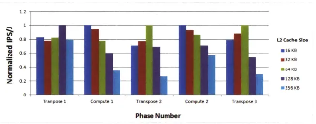
Figure 2.1: Normalized energy efficiency results for
fft
using different L2 caches, divided across phases. The target architecture has 64 cores and an 8KB Li Cache.FFT with three transpose phases interspersed with two compute phases [2]. Figure 2.1 is generated by the experimental methodology described in Section 5.1.1, and shows the energy efficiency of different L2 cache sizes on a 64-core architecture.
During the transpose phases of
fft,
the application is dominated by memory opera-tions, and during the compute phases the application is dominated by compute operations. As a result, the demands on the cache are greater in the transpose phases than the compute phases, but it is evident in the figure that this relationship is non-trivial. Depending on how warm the caches are before each phase, the actual efficiency of the cache can vary. In fact, the first transpose phase shows a larger cache demand than the pursuant transpose phases. Small caches are predictably efficient during the compute phases. Due to the con-flicting nature of these phases, there is no single resource distribution that can be optimal for both: if a 64KB cache was implemented, then the Compute 1 phase is 78% optimal, whereas if a 16KB cache was implemented, the Transpose 2 phase is 70% optimal. An ideal scenario would feature a cache that can adapt its size to the appropriate phase, so that energy consumption is optimized for the necessary performance.2.1 Overview
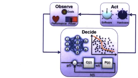
Figure 2.2: Graphical representation of an Observe-Decide-Act loop in a self-aware system.
A final challenge with multicore scaling is that it also increases the chances of unfore-seen events during the execution of the application. This could be a thermal emergency that may throttle the speed of a core, or an error that restarts a part of the application. These are cases that a statically configured system has no means of resolving, but an intelligent self-aware system can deal with in stride.
2.1.2 Observation-Decision-Action Loops
The common denominator of all self-aware systems is the negative feedback loop that cor-rects the error between the current and target state. At a high level, this feedback loop is driven by continuously observing system behavior to determine how close it is to its goals, deciding based on these observations what it can do to achieve the goal, and then
acting out its decision by tuning the available knobs. Hence, these loops are known as observe-decide-act (ODA) loops [6,15], and are illustrated in Figure 2.2.
contains an ODA loop. In this subsection we will show how the ODA model fits in two ex-isting self-aware systems, noting that the implementation of the ODA loop varies drastically in literature [9,16-18].
In the adaptive processing system described by Albonesi et al. in [1], a number of microarchitectural mechanisms are built for configurability. Depending on statistics gath-ered by the controller, the system dynamically adjusts the issue queue, load/store queues, reorder buffer, register files, and the instruction cache to match the utilization demand. Observations are made by monitoring a number of performance counters built into the hardware, and decisions are made to adapt the knobs when the counters trigger specific events. For example, the average occupancy statistics of the issue queue are tracked by a counter, and if a smaller queue is sufficient to hold the average number of instructions, an event is triggered and the queue downsizes; if an overflow occurs, the adaptive issue queue upsizes. This sort of ODA loop is present in many parts of the system. Figure 2.3 illustrates the adaptive processing system of [1] superimposed with the associated ODA loops. Note that, in this case, the ODA loops are built directly into hardware, and they all function independently.
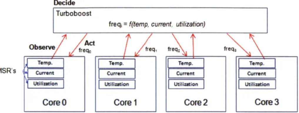
Intel's Turboboost feature controls the frequency of its cores to maximize perfor-mance [19]. If a core is heavily used, Turboboost can tune up the frequency of that core. On the other hand, if a core is lightly used, Turboboost can tune down the frequency, or even power gate the core to yield even larger power savings. Observations are made by hardware counters implemented as MSRs (Machine State Registers), and the decision for the frequencies of the cores is ultimately constrained by power delivery limits, current con-sumption, and temperature. When Turboboost decides that the statistics are under the constraints, it steps up the frequency of the active cores. Figure 2.4 shows the associated
ODA loops on Turboboost.
2.2 Uncoordinated Adaptive Systems
Observe p e
Decide counter
Obsere missrate>? Observe Decide aver eos, pancy utiiaion=? t erd bunter g overfow?
miss rat av ea ccpancy A t
-- Q -- ALUI
L1|$ -- Fetch Logic - ROB
-loop IObserve
~we~ counter
miss rate ee
s Obsrve te ce Dede the y L1 eD$ Decide Act
cone utilization ?
averuge ocfpad y F e miss rate >?
Figure 2.3: Adaptive microarchitecture in [1]. The shaded components are designed for adaptivity, and each adapt to application demands through independent ODA loops. Ob-servations are made by built-in performance counters, and decisions are made by events triggered by the counters.
system: each adaptive component in Turboboost does not have its own independent ODA loop. Instead, there is a single decision engine that collects all the observations from the cores, and makes a decision on the core frequencies based on the state of the global system. Nevertheless, both Albonesi's adaptive processing systemand Tes Tems are equally valid self-aware controllers, and both rely heavily on ODA loops.
2.2
Uncoordinated Adaptive Systems
Most self-aware systems, such as those explained above, do very well in their sphere of in-fluence. A major drawback, however, is that because they only have knowledge of their own knobs, they do not work well with other sources of adaptivity. Fo r example, in the adap-tive processing system described in the previous section, all of the adaptivity is built into hardware, and so application-level goals are beyond the scope of its observations. Software-based approaches, on the other hand, will assume that the hardware is fixed and make no attempt to coordinate with these low-level adaptations. These systems are closed to
Decide Turboboost
freq= f(temp, current, utilization)
Observe fr freq, freq2 freqa
Temp. TemTemm Te..
S R's i currentcuetCurn rrt
Core0 Core1 Core2 Core3
Figure 2.4: Intel Turboboost ODA loop. Core frequencies are determined by a global controller that makes decisions using observations on all cores in the system.
other levels of adaptivity, and cannot coordinate with others; we refer to such systems as
closed/uncoordinated adaptive systems.
Of course, this is not an issue if there is only one single adaptive mechanism in the system. However, future systems will have many resources that are capable of being adaptive, and the impact of each knob on the other cannot be ignored. Simply running multiple ODA loops in hardware and software simultaneously is not a valid solution either, because even with both loops targeting the same goals, it is almost impossible for each loop to make intelligent decisions without understanding the impact it has on the rest of the system. For example, two closed ODA loops running at the same time and targeting the same application performance goal might realize the system is underperforming, and in response both allocate extra resources. More likely than not, the next observation by the controller will find that the system is over-performing, because both loops independently added enough resources to make up the performance deficit and over-provisioned the system. In response, both controllers remove resources from the application, and the system never converges to an optimum.
The root cause of this problem is the existence of configurations that are sub-Pareto optimal. Consider a system with the competing goals of performance and energy: a Pareto
2.2 Uncoordinated Adaptive Systems
optimal configuration is a configuration that runs with maximum performance and mini-mum energy. With the sheer number of configurations available in a massively multicore processor, the fact that some combinations of those knobs are sub-Pareto optimal configu-rations is not surprising. However, in general, Pareto-optimal points are the only ones that a controller in a self-aware system should ever consider. Unfortunately, without a sense of how other knobs behave, an uncoordinated controller has no way of gauging the global Pareto optimality of its actions.
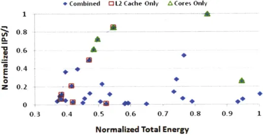
To illustrate this, we explore the behavior of the barnes application from the SPLASH2 benchmark suite (see Section 5.1 for details on methodology) on a multicore system with two knobs: the total number of cores assigned to it (from 1-64, by powers of 2), and the size of the last-level cache on each core (from 16-256KB, by powers of 2). We simulate each configuration on the Graphite simulator
[14),
measure application performance in in-structions per second, total energy consumption in joules, and plot the normalized results in Figure 2.5. The solid diamond points represent all simulated configurations; the squares show configurations that appear optimal for a closed system which only considers cache adaptations; and the triangles show optimal configurations for a system that only considers core allocations. The Pareto-optimal frontier is depicted by those diamond points that are connected together. Notice there are triangles and squares that appear below the Pareto frontier: these points represent configurations that uncoordinated systems would believe to be optimal, but, in fact, are sub-optimal for the overall system. For the closed systems, these states are Pareto-optimal within its own space of possible configurations, but they are clearly sub-optimal in the global system.To avoid sub-optimal configurations, adaptivity needs to be considered as a first
class object, so that all knobs are considered globally instead of in piecewise,
uncoordi-nated objects. In a coordiuncoordi-nated self-aware system with a global view of all the knobs in the system, sub-optimal configurations can be filtered out and discarded, leaving only the
* Combined L2 Cache Only MCores Only 1 0,:8 0.6 M
0.4
0 0.3 0.4 0.5 0.6 0.7 0.8 0.9 1Normalized Total Energy
Figure 2.5: Normalized efficiency of barnes. The Pareto frontier is shown as the blue connected line.
Pareto-optimal configurations as actions for the ODA loop (the Pareto frontier).
2.3
SEEC Framework
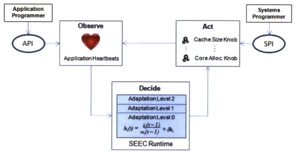
In [15], Hoffmann et al. proposes the SEEC (SElf-awarE Computing) framework. In the SEEC model, there are three distinct roles with distinct responsibilities:
Role Responsibilities
Application Developer Specifies application goals.
Systems Developer Specifies actions in the form of subroutines that tune the knobs.
SEEC Runtime System Observes the system and determines the amount of speedup needed to achieve goal; decides on appropriate actions
Table 2.1: Roles and responsibilities in the SEEC model.
Note that the application developer is completely relieved from the optimization task, and needs only to set the performance goal that he/she desires. All adaptive knobs are registered into the SEEC framework by the systems programmer, who is exactly the
2.3 SEEC Framework
Observe Act
7 5 7 ,
- £ CacheSizeKnobApplication Heartbeats CoreAloc Knob
Decide Adapteihntevd 1
SEEC Runtime
Figure 2.6: The SEEC model.
individual most familiar with a systems underlying adaptivity. Since all the knobs are registered in one place, SEEC filters out all sub-Pareto optimal configurations that would otherwise plague an uncoordinated adaptive system.
In this thesis, we will be using SEEC as the self-aware controller for our architecture, and use it to explore the effectiveness of the proposed knobs. A full description of SEEC can be found in [13], but is mostly beyond the scope of this thesis. Instead, we will describe only those features that are important for our interests. Figure 2.6 serves as a reference for the following subsections.
2.3.1 Observation
Application goals are specified through an API provided by the SEEC framework, which provides an abstraction of performance in the form of an Application Heartbeat [20]. The application developer instruments the application to emit heartbeats at important intervals, and sets the desired heart rate. The programmer can also specify the size of a rolling
window, which acts as a low-pass filter to smooth out the heartbeat data. This abstraction level allows the programmer the purchase for setting fine-grained goals, without having to understand the lower level features of the system itself.
It is interesting to point out that, unlike the self-aware systems we have already dis-cussed, goals in SEEC are specified directly by the application developer. In the previous discussions, systems are optimized with extreme goals: run an application with maximum performance, run an application with minimum energy consumption, etc. While this does mean that these systems can run without any instrumentation in the application, it also means that there is no way for these systems to target application-specific goals. For in-stance, consider the target performance for a video encoding application: it could be 30 frames per second, 40 frames per second, or any number deemed necessary by the devel-oper; there is no way for the application developer to specify such a goal. On the other hand, SEEC assumes that the application developer has the most knowledge of application demands, and provides the heartbeats interface to communicate these goals.
2.3.2 Decision
SEEC's decision engine is divided into several levels. At the simplest, or Adaptation Level 0, the decision engine is a basic model-based feedback controller. This controller continuously monitors the heart rate h(t), and compares it with the target heart rate g to compute the required speedup s(t). Using the set of actions made available by the system programmer and their associated models, SEEC decides on the appropriate action (or combination of actions) to move the system closer to its goals. This basic control system is the backbone of all the engines available.
The next level of sophistication, or Adaptation Level 1, addresses the issue of work-load estimation. While the heart rate, h(t), measured by SEEC is a general indicator of
2.3 SEEC Framework
the latency between heartbeats, it is not a direct measurement of application performance. This is because the actual application performance also depends on the actual work done. That is, the heart rate h(t) can increase either because the system is performing more ef-ficiently, or the actual work being done for the application has decreased. In Adaptation Level 0, the work done is assumed to be time invariant, but this is patently untrue for some applications (i.e., a video suddenly becomes more difficult to encode). In Adaptation Level 1, a 1-dimensional Kalman filter is used to estimate the workload of the application. This increases the speed of convergence substantially.
Adaptation Level 2 addresses the accuracy of the models provided to SEEC. While the Kalman filter can estimate application workload, it cannot differentiate between cases where workload actually changes, and cases where the action models provided by the sys-tems programmer are inaccurate. The fact that the action models could be erroneous is not unlikely, because a single model for a knob is unlikely to be appropriate for all applications (although we discuss including multiple models per knob in Section 6.2). As an example, consider the knob that tunes the total number of cores available to an application. Obvi-ously, depending on the application, the limits of parallelism will provide different speedup tradeoffs. Incorrect models imply that SEEC will select actions that are sub-Pareto optimal, because it will adjust to changes in estimated workload that might not exist. In Adaptation Level 2, another Kalman filter is used to estimate the actual cost and benefits of an action, and modifies the models if it finds them incorrect. In this way, SEEC gradually learns the correct action models, and will be able to recompute Pareto-optimal actions on-the-fly.
2.3.3 Action
The systems programmer specifies the action model for a knob by providing a set of actions A0, A1, .., A., and associating a relative speedup and cost over the baseline action A0,
which by definition has a speedup and cost of 1.
Action Speed-up Cost Description Ao 1.0 1.0 1 allocated core
A1 2.0 2.0 2 allocated cores
A2 3.0 3.0 3 allocated cores
Table 2.2: Example action model for core allocation knob.
For example, to specify actions for the knob that tunes the number of cores available to an application, the baseline action Ao represents the allocation of a single core. Action A1 might represent the allocation of two cores, and the associated speedup and cost could be set as 2.0, which represents double the performance and cost, and so on. This is shown in Table 2.2.
The systems programmer provides a set of actions for every knob, and SEEC inter-prets the combination of multiple knobs as the product of the associated speedup and cost for each constituent action. The flexibility of this framework allows several different systems programmers to provide action models for the knobs they are most familiar with. It also allows the removal and addition of knobs as is appropriate, which allows SEEC to use new knobs or a subset of existing knobs. If the models are accurate, SEEC will rapidly converge to the optimal configuration to achieve the specified goals. In the case that the models are inaccurate, either due to a single knob or a combination of them, the Adaptation Level 2 in SEEC's decision engine will resolve the inaccuracies.
-Chapter 3
Angstrom:
A Massively Multicore
Self-Aware System
3.1
Architecture Overview
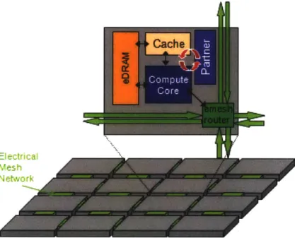
Angstrom is a large, cross-disciplinary project that aims to create a fundamentally new system to meet the challenges of extreme-scale computing. Solutions are posed for challenges at all levels, from circuits, to architectures, to operating systems, to applications. For this thesis, we will be using the Angstrom proposal as the backbone architecture for our study. The full specification of Angstrom is, of course, well beyond the scope of this thesis, but there are two important features of Angstrom that are relevant to our interests.
First, Angstrom is proposed as a massively multicore processor, with up to a thou-sand cores. This proposal comes from a projection of the multicore scaling trend, which has seen the number of cores double every three years since 2006 [4]. Cores in Angstrom are organized as a tile-based architecture, connected by a mesh network with endpoints at
Figure 3.1: The Angstrom architecture.
each tile. Figure 3.1 illustrates a basic picture of the Angstrom architecture.
Cores in Angstrom are much simpler relative to modern processors, which otherwise have large re-order buffers, superscalar issue width, and a considerable number of pipeline stages. These architectural features are useful because they substantially improve perfor-mance, but come at the expense of high energy consumption. For future technologies, where transistor density will increase exponentially, the tradeoff of energy for performance is not as forgiving as in previous generations. In fact, the heat dissipated from the transistors pose a hard limit to the total number of active components, forcing large numbers of transistors to be powered off at any one point in time. Studies predict that at 8nm, up to 50% of a chip could be forced to be powered down, coining the term dark silicon to describe devices that cannot utilize all its constituent transistors simultaneously [5]. Therefore, it is important for a massively multicore system like Angstrom to be extremely energy-efficient. Notwith-standing, the actual hit in performance from removing the complex architectural features
3.2 Observation
is not fully realized anyway, because even if they were left in place, most of them could not be powered on for doing useful work. Adding to the fact that a massively multicore system targets parallel applications instead of sequential ones, then simple in-order cores are perfectly reasonable for Angstrom.
The second feature of Angstrom that is relevant to our interests is that it is designed to treat adaptivity as a first-class object. This means that all components of the architecture are designed to contribute to the specification of the ODA loop. As such goals are specified through a single interface, the self-aware controller will have purchase to adapt all levels of adaptivity to accomplish them. Angstrom uses the SEEC model, and exposes a wide array of both hardware and software observations and actions to the SEEC runtime. In the following sections, we will describe in detail the features in Angstrom that contribute to the ODA loop.
3.2
Observation
To provide SEEC appropriate feedback to model the tradeoffs associated with its knobs, Angstrom provides a means to monitor both performance and power. As we will describe, Angstrom goes beyond normal architectures to provide a level of introspection for SEEC that would be impossible on a traditional system.
3.2.1 Performance Monitoring
The main interface for setting goals and observing the performance of the system is pro-vided by the Application Heartbeats API described in Section 2.3.1; this is an architec-ture independent feaarchitec-ture, and is not reliant on Angstrom in any way. However, beyond the application-level performance monitoring enabled by the Application Heartbeats API,
Angstrom also provides several hardware features that provide valuable insight into the application behavior on the underlying architecture.
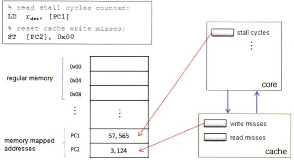
The first such feature is the implementation of performance counters. Of course, existing systems already possess a number of performance counters, but most of them either impose strict limitations to the number of counters that can be monitored simultaneously, or require heavy kernel interaction for each access [21]. As a result, either multiple profiling runs are required to comprehensively pre-analyze an application, or the programmer is left with limited and possibly out-of-date information about the system.
In Angstrom, all performance counters are exposed directly to software by mapping a portion of memory dedicated to observation hardware. As such, all levels of the software stack have access to all of the counters. This not only allows SEEC to gather informa-tion from all the counters at one time, but provides low enough overhead per access to allow SEEC to dynamically analyze the information during runtime. Counters enumerate any events that may provide insight to application behavior. Some examples include: the number of cache hits and misses, pipeline stall cycles, network flit traffic, etc. Figure 3.2 illustrates the architectural design of the performance counters.
Since performance counters are only enumerators, it is far too expensive for a runtime system to continuously poll them for information, especially if it is trying to observe the occurrence of a rare event. For such cases, Angstrom provides event probes that can be associated to a performance counter, or some other architectural state. These event probes contain a programmable comparator that continuously watches for a specific state, and triggers an interrupt when the event occurs. Event probes can be set to different operations - such as equal to, greater than, or less than etc. - and may be masked to only watch selected bits. In any case, programmable event probes effectively move the busy-polling loop from software to hardware.
3.2 Observation
' read 5all cycles counter:
LD rdaS, [PC1]
% rese: cache write misse5:
ST [PC2], OxOO regular memory memory mapped addresses
I
0x04 0x04 PCi PC2Figure 3.2: Performance counters are memory mapped, access is made through regular load/store instructions.
3.2.2
Energy Monitoring
To effectively monitor the performance versus power tradeoff, the self-aware runtime re-quires some sort of energy consumption feedback. Accurate measurements of energy allow the controller to gauge the actual effect of its actions during exploration. In modern sys-tems, power can be measured either by placing current meters at major power delivery inputs of the system, or through an ad-hoc power model developed to estimate the energy consumption of the specific architecture. The former approach fails to provide fine-grained information on energy efficiency, and the latter is only as accurate as the model, which can be especially vulnerable to rare corner cases, or unforeseen events such as thermal emergencies.
Accurate, fine-grained power monitoring is key to architectural adaptivity because it shows exactly which components of the system are the least efficient, allowing SEEC to target knobs for improving efficiency on exactly those components. Otherwise, SEEC runs the risk of unknowingly sacrificing the performance of components that might otherwise be efficient. For example, consider an application that is compute-bound and uses very few cache accesses, then the focus of optimization should be localized around the computational part of the system. Application Heartbeats has no means of conveying this information a priori; without fine-grained energy measurement, it is up to SEEC to discover the energy tradeoff through exploration of the configuration space in both components. To be sure, SEEC will eventually converge to the optimal configuration, but power observation can improve the performance of the SEEC runtime.
To motivate fine-grained energy observation, we study the
fft
application first de-scribed in Section 2.1.1. This Fast Fourier Transform algorithm alternates between a trans-pose and computation phase, which alternately stresses different parts of the core architec-ture. Figure 3.4 shows the dynamic energy breakdown offft
across the two phases. During3.2 Observation
ift (transpose phase) fft (compute phase)
0 Cache Dynamic Energy
4 L
: a Core Dynamic Energy
Figure 3.4: Breakdown of cache and core component energy between phases in the
fft
benchmark.
the transpose phase, when
fft
is focused on memory operations, the core pipeline spends most of its time stalled. The results show that during this time the core consumes only 21% of dynamic energy, but core dynamic energy consumption jumps to 93% during the compute phase. This information is extremely insightful, as it can direct the optimizations in a very clear direction, allowing any self-aware controller to converge to an optimal configuration much faster.This leaves the question of implementation. One way to provide this feature is to implement circuits to monitor energy directly on-chip. One approach is to track the current through the component under measurement, and the number of times it charges a pre-defined capacitance. This number can then be converted to a power measurement by comparing dividing the count with the system cycle counter:
P
#
cap charges x Vcap#
cycles elapsed xf
The counters that track the number of capacitor charges and the system clock cy-cles are exposed to software as memory mapped locations, much like performance counters. Therefore, accessing power information has the same overhead as any regular load or store for memory mapped registers. Note, to allow for power measurements during specific
win-clk
cVap # cycles
sensor
# cap charges
Figure 3.5: Block diagram of energy monitor circuit.
dows of time, the energy monitoring register can be reset. Figure 3.5 is a high-level diagram that shows how such a circuit is implemented.
By integrating multiple energy monitoring circuits within a single tile, Angstrom provides a granularity of observation to SEEC never before available. Any such number of these energy monitoring circuits can be implemented, limited only by the area available. One concern is that current prototypes of this circuit use an off-chip capacitor to serve as Vcap. This may stress the I/O constraints of the physical chip, and add considerable routing complexity to connect the I/Os to every single energy monitoring circuit. However, work in integrated switched capacitor technology has been promising, and can potentially be used as a replacement for off-chip capacitors.
3.3
Decision
As we described in Chapter 2.3.2, the SEEC runtime has a decision engine that dynamically converts observations from the system into actions for its knobs. Unfortunately, this type of self-awareness does not come for free: the decision engine is real code, and must be given some execution context to run upon. Angstrom provides a number of places to run the
3.3 Decision
SEEC code:
(i) Instrumented Source The decision engine code is instrumented into the same context as the application.
(ii) Same Core The decision engine code is run in a separate thread on the same core, and receive heartbeats through the built-in API.
(iii) Separate Core The decision engine code is run in a thread on a separate core.
(iv) Partner Core The decision engine code is run in a separate thread on a specialized, low-power core.
The efficiency of each approach can be summarized by two key metrics: communi-cation latency and applicommuni-cation slowdown. Communicommuni-cation latency is related to the speed in which SEEC receives observable data, and the speed that it can effect change to the tile containing the application; this is important because it directly affects the speed in which SEEC can make adjustments. Application slowdown, for obvious reasons, is undesirable in
terms of application performance. Table 3.1 summarizes each approach. Communication Latency I Application Slowdown
Instrumented Source Low High
Same Core Low Low to High
Separate Core Med to High None
Partner Core Low None
Table 3.1: Characteristics of SEEC decision engine placement.
The instrumented source approach epitomizes low communication latency because it is co-located with the application thread, but suffers from slowdown because the application must stop to allow the SEEC code to run. In the same core approach, or similarly an SMT approach, communication is still cheap because hardware is still shared between the threads. The application slowdown, however, is application specific. Slowdown could be kept low if the scheduler is able to execute the SEEC runtime during periods where the application thread is otherwise stalled. In cases where this is not possible, the application thread must stall and wait for the SEEC thread to compute its decisions, resulting in substantial application slowdown. On the separate core approach, the SEEC thread is completely
decoupled from the application, allowing it to make its decisions asynchronously. The communication latency can be variable, as it is a function of the distance between the cores executing the SEEC runtime and the application. At best, the SEEC runtime thread is scheduled on a tile adjacent to the application, which is inherently slower than the previous two approaches but still reasonable. However, in the case where the SEEC runtime is scheduled on a tile several network hops away, the communication latency grows quickly.
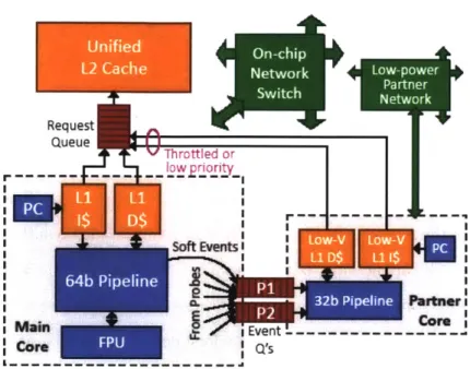
To address all these issues, Angstrom provides a novel architectural feature, called
Partner Cores, to allow for low-latency communication and no application slowdown. At
a high-level, a partner core is simply a small, low-power core on the same tile as the core running the application. The uniqueness of the partner core is its emphasis on low power rather than performance, and the way in which it communicates to the application core. To minimize the power consumption and area of the partner core, each partner core includes a low-power pipeline with very few architectural frills. Such a pipeline will be much slower than the application core, but this is acceptable because SEEC makes its decisions asynchronously and can avoid application slowdown. To observe and communicate with hardware, the partner core makes use of direct hardwired connections to the main cores hardware, resulting in bare minimum communication latency (Figure 3.6). Details of the partner core architecture are described in [22], so we will not include them here.
3.4
Action
The Angstrom processor provides several adaptive mechanisms, or knobs, that can be tuned on-the-fly by SEEC to reflect the speedup changes deemed necessary by its decision engine. To register knobs with SEEC, the programmer must associate each knob configuration with a speedup and cost, and then provide a valid subroutine that modifies the values in the appropriate memory-mapped locations. Depending on where in the compute stack a knob
3.4 Action
Figure 3.6: Architecture of a single tile in the Angstrom architecture, showing the main and partner cores.
is located, knobs may be registered by different developers.
If a knob is built in hardware, such as a knob that tunes the cache size or instruction issue width, Angstrom will map the relevant control hardware into memory. Thus, a normal load and store to the appropriate location can directly adjust the underlying hardware. The process of creating these hardware interfaces is the responsibility of the architect, and is completely invisible to the application developer. A detailed example of how such an interface is built will be given in Chapter 4.
If a knob is built in software, such as a knob that schedules threads on cores, the system programmer must again provide the appropriate subroutine and associated speedup and cost. Unlike hardware-based knobs though, which are fixed with the specific processor architecture, there is no limitation on the number of software-based knobs. To be sure, designing a software-based knob requires deep knowledge of the system, and likely also
![Figure 2.3: Adaptive microarchitecture in [1]. The shaded components are designed for adaptivity, and each adapt to application demands through independent ODA loops](https://thumb-eu.123doks.com/thumbv2/123doknet/13861291.445540/23.918.155.763.204.426/figure-adaptive-microarchitecture-components-designed-adaptivity-application-independent.webp)
![Figure 4.1: Miss rate vs. cache size and associativity for the SPLASH2 benchmarks, taken from [2].](https://thumb-eu.123doks.com/thumbv2/123doknet/13861291.445540/45.918.135.744.279.699/figure-miss-rate-cache-associativity-splash-benchmarks-taken.webp)
