Automatic Implementation Generation for
Pervasive Applications
by
Justin Mazzola Paluska
Submitted to the Department of Electrical Engineering and Computer
Science
in partial fulfillment of the requirements for the degree of
Master of Engineering in Electrical Engineering and Computer Science
at the
MASSACHUSETTS INSTITUTE OF TECHNOLOGY
June 2004
c
° Justin Mazzola Paluska, MMIV. All rights reserved.
The author hereby grants to MIT permission to reproduce and
distribute publicly paper and electronic copies of this thesis document
in whole or in part.
Author . . . .
Department of Electrical Engineering and Computer Science
May 13, 2004
Certified by . . . .
Steve Ward
Professor
Thesis Supervisor
Accepted by . . . .
Arthur C. Smith
Chairman, Department Committee on Graduate Students
Automatic Implementation Generation for Pervasive
Applications
by
Justin Mazzola Paluska
Submitted to the Department of Electrical Engineering and Computer Science on May 13, 2004, in partial fulfillment of the
requirements for the degree of
Master of Engineering in Electrical Engineering and Computer Science
Abstract
Pervasive computing promises to put computers in almost every corner of our life. Unfortunately, it also promises to make programmers’ jobs harder since they cannot know what components are available in the run-time environment and as such, cannot statically plan out their programs. To help this situation, we propose goal-oriented programming, which may be more amenable to programming pervasive applications. Goal-oriented programming adds a level of indirection between Goals, high-level intentions such as “make me available for chat,” and Techniques, the code that im-plements the intentions. Each Technique is a combination of code and prerequisite subgoals, so that a Technique can be itself goal-oriented.
By decomposing an application this way, it is possible to automatically build parts of it based on the runtime environment. When an application would like a Goal satisfied, the implementation Planner first finds Techniques that can satisfy the Goal, and then recurses to satisfy the Techniques’ subgoals. After a sufficient number of Techniques are found, the Planner evaluates the Techniques in some user-defined way, and chooses a set to execute.
This work focuses on programming framework that isolates the planning aspect of goal-oriented programming from the Goals and Techniques themselves. We provide a reference Planner and evaluate its how well the Planner performs in simulation. Thesis Supervisor: Steve Ward
Acknowledgments
First, I would like to thank my advisor Steve Ward, with whom I had innumerable discussions that helped me identify the important problems that my thesis should try to solve. His comments on the thesis paper itself also helped me significantly tighten the prose and emphasize important points.
Thanks also go to Dr. Umar Saif and Hubert Pham. Umar listened to many of my implementation and design ideas and helped filter out the less useful ones. Hubert helped in the final days of thesis writing by editing drafts of this documents late at night.
I would not have been able to write my thesis with out the help of all of my friends and family. In particular, my mom and sister have helped me so much by encouraging and supporting me over the past few years. They are the foundation on which I have been able to grow. Finally, I would like to thank Trisha Montalbo for putting up with me, making cookies appear at precisely the right time, and just in general being there for me as I stressed over my thesis.
Contents
1 Introduction 13
1.1 Goal-oriented Programming . . . 14
1.2 The O2S System . . . 15
1.3 Thesis Outline . . . 16
2 Overview of Goal-oriented Programming 17 2.1 Goals . . . 17
2.2 Techniques . . . 18
2.3 Planner . . . 19
2.4 An Example: Goal-oriented Conferencing . . . 19
3 Related Work 23 3.1 make . . . 23
3.2 Multiple Dispatch . . . 24
3.3 Planning in the ai Community . . . 24
3.4 Heuristic Search . . . 25
3.5 Recent Systems Developments . . . 26
4 Design Challenges 27 4.1 A Typical Planner/Technique Interaction . . . 28
4.2 Construction . . . 30
4.3 Evaluation . . . 31
4.3.2 Evaluation Reach . . . 32
4.3.3 Changing Evaluation with Time . . . 33
4.4 Execution . . . 33
4.5 Error Handling . . . 34
5 Design 35 5.1 Simplifying Assumptions and Clarifications . . . 35
5.2 Technique Discovery . . . 36
5.3 Satisfaction: A Uniform Evaluation Value . . . 37
5.4 The Planner api . . . 38
5.5 The Technique api . . . 40
5.5.1 Phases of Goal Resolution . . . 40
5.5.2 Event Handling . . . 42
5.6 Satisfaction api . . . 42
5.7 Goal-oriented Conferencing Revisited . . . 43
6 Implementation 45 6.1 Writing a Parallel Planner . . . 45
6.2 Physical Code Structure . . . 47
6.3 The O2S Programming Environment . . . 48
6.4 Runtime Code Structure of the Planner . . . 49
6.4.1 The Plan Object . . . 50
6.5 The EventFramework . . . 51
6.5.1 Implementation of the EventFramework . . . 52
7 Performance Evaluation 55 7.1 Scenario Anecdotes . . . 55
7.2 Performance . . . 56
7.2.1 Test Methodology . . . 56
7.2.2 Satisfy Performance on Full Trees . . . 57
7.2.3 Satisfy Performance on Long, Scrawny Trees . . . 63 8
7.2.4 Fail-Over Performance . . . 63
8 Conclusion 67
8.1 Future Work . . . 67
List of Figures
2-1 Stages of a Goal-oriented Teleconference . . . 20
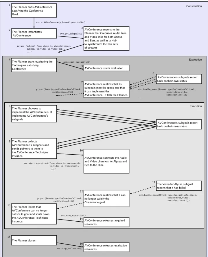
4-1 A transcript of the interaction between the Planner and the AVConference Technique in the example scenario. . . 29
5-1 Illustration of the Goal-oriented programming system’s architecture. . 36
5-2 Planner api used by Techniques . . . 39
5-3 api for Techniques . . . 40
5-4 Each function call the Planner makes moves the Technique into a dif-ferent phase. . . 41
5-5 The Satisfaction api the Planner exports to Applications. . . 42
5-6 The sample interaction between the Planner and the AVConference Technique Instance annotated with the api calls that each makes. . . 44
6-1 Simple Plan Tree . . . 46
6-2 The runtime environment of O2S. . . 48
6-3 The runtime structure of the Planner. . . 49
6-4 api exported by the EventFramework. . . 52
6-5 The runtime structure of the EventFramework. . . 53
7-1 Application code to run the scenario. . . 55
7-2 Latency for plan trees of varying size and no evaluation delay. . . 58
7-3 Latency for plan trees of varying size and 6ms evaluation delay. . . . 59
7-4 Latency for plan trees of varying size and 250ms evaluation delay. . . 60
7-6 Latency for scrawny trees of varying height and no evaluation delay. . 63 7-7 Latency for scrawny trees of varying height and an evaluation delay of
6ms . . . 64
7-8 Latency for scrawny trees of varying height and an evaluation delay of
250ms. . . 64
7-9 The tree used for the fail-over tests. . . 65
7-10 Re-plan delay as a function of how many tree levels must be re-planned. 65
Chapter 1
Introduction
Pervasive computing promises to put computers in almost every corner of our life. Conventional computers will interact with new computers in appliances, cars, build-ings, and other electronic jewelry. In such a world, users will expect their devices to be aware of their environment and maintain services in the face of radical changes in the computational environment.
For example, suppose Alyssa would like to communicate with Ben. In a pervasive computing environment, all Alyssa should do is request a conference with Ben and the environment should take care of the rest. If both parties both have phones, perhaps a phone call is the best way to conference, while if they have access to video equipment, the two should be connected by video. In other words, the conference software should make use of the best components available in the environment. Furthermore, suppose that after establishing the conference, Alyssa needs to walk out of her office, but would like to continue talking with Ben. When Alyssa leaves, the conference should switch over to using her cellular phone, since it is the best way for her to stay connected and be mobile.
An application that supports such a rich variety of conferences is hard to pro-gram. In a traditional computing environment, it is nearly impossible: Alyssa and Ben would need to agree beforehand what kind of conference they want, fire up their conferencing software, and restart the conference when some parameters of the con-ference (such as location) change. Pervasive environments typically offer a variety of
frameworks to make this task easier, ranging from discovery tools to pluggable com-ponents. However, even with such frameworks, the programmer cannot know what components are available in the environment and as a consequence, cannot statically plan programs.
Luckily, the programmer still has control over and can statically plan two levels of a pervasive application. The first is the high-level intents the application has. The second level is the many individual recipes that implement intentions. What is needed, therefore, is a framework for dynamically choosing, instantiating, and connecting code modules to maintain some higher-level intent.
1.1
Goal-oriented Programming
This thesis proposes Goal-oriented programming as a way of constructing pervasive applications. Goal-oriented programming makes explicit the separation between in-tent and implementation. The hope is that by exploiting the underspecified nature of many intents, the system can automatically choose among different ways of imple-menting each intent.
In a Goal-oriented program, the application asks a Planner to satisfy a high-level intent—embodied as a Goal. The Planner then matches the Goal against a repository of Techniques satisfying the Goal. If there are many Techniques satisfying the Goal, the Planner must choose one among them. Next, the Planner executes the Techniques it has chosen. Finally, as the environment changes, the Planner revisits its set of chosen Techniques and may choose a new set to satisfy the Goal in the changed environment.
Goal-oriented programming offers two key advantages over existing programming methodologies:
1. A Goal may be satisfied in a myriad of ways, each of which is best suited at different times. Since the Planner evaluates and monitors each of the Techniques satisfying a Goal, the Planner may progressively refine its implementation as the environment changes.
2. New capabilities may be built into old applications by simply adding new Tech-niques. The Planner will incorporate the new Techniques in the course of sat-isfying future Goals.
These advantages greatly ease the job of writing an adaptive pervasive application.
1.2
The O2S System
Goal-oriented programming is motivated, in part, by our experience maintaining ap-plication services in O2S[13], a typical pervasive computing environment. O2S gives programmers three primitive types—Resources, Events, and Connectors—on top of which the programmer can layer any pervasive application. Resources are generic net-work objects that provide access to services through synchronous requests. Events are asynchronous messages and notifications generated by Resources. Finally, Con-nectors are low-overhead network sockets that can be used to stream data between two Resources. In addition to the primitive types, O2S also provides a framework to discover and acquire additional resources, as well as monitor the health of the existing resources.
Hence, O2S provides an environment where pervasive applications can be com-posed by discovering resources, connecting them together, and handling events as necessary. However, much of this work is mundane and, moreover, error-prone as the programmer must be careful to handle all execution modes. To make matters worse, the logic of handling failures and adapting to changing environments is often scattered in many parts of the program, making it hard to maintain. Finally, even given perfect adaptability, making rich use of the computing environment is difficult since knowledge of new capabilities needs to be built into the application before they can be used.
Goal-oriented programming provides a way mechanize much of this work as well as a way of concentrating adaptation logic in the Planner.
1.3
Thesis Outline
The next two chapters present an overview of Goal-oriented programming and related work. Subsequently, Chapter 4 outlines the constraints and goals we tried to meet when creating our design. Chapters 5 and 6 detail our final design and implemen-tation. Chapter 7 evaluates our implemenimplemen-tation. Finally, Chapter 8 outlines future work and concludes.
Chapter 2
Overview of Goal-oriented
Programming
Goal-oriented programming centers around three main concepts: Goals, Techniques, and the Planner.
2.1
Goals
A Goal is a parameterized specification of a class of high-level applications intents or desires. A Goal instantiated with a particular set of parameters is formalized as a Goal Instance. Goals specify both the type and meaning of their parameters as well as the type of value returned by a particular Goal Instance.
A Goal is analagous to a function specification. Likewise, a Goal Instance is much like a function call. However, there are a few differences between function calls and Goal Instances:
1. The usual job of a function call perform a calculation or mutate state. A Goal Instance, on the other hand, maintains an intent. In the process of maintaining the intent, the Goal Instance may perform many of the same actions that a function call may. However, unlike the “call and return” semantics of a function call, a Goal Instance persists until an application no longer needs the intent
maintained. In other words, a function call executes once, while a Goal Instance runs continually and adapts as the environment changes.
2. A function call maps to exactly one body, while a Goal Instance has many ways of being satisfied. It is the responsibility of the Planner to match appropriate Techniques to the Goal Instance and make sure that these Techniques still satisfy the Goal as the environment changes.
2.2
Techniques
A Technique is a parameterized template for satisfying a Goal. A Technique itself may be goal-oriented by declaring prerequisite subgoals that the Planner must satisfy. Goal Instances are satisfied by Technique Instances, which are Technique objects with their parameters bound to the parameters of the Goal Instance that the Technique Instance is to satisfy. Each Technique declares which class of Goals it can satisfy. However, at runtime each Technique Instance works with the Planner to decide how well, if at all, it can satisfy its particular Goal Instance. This is necessary since the Planner must make an informed decision among the many Technique Instances that satisfy any particular Goal Instance.
Since Techniques are recipes for satisfying Goals, a Technique contains arbitrary code that allows it to interact with the Planner, its own subgoals, and the world at large. Conceptually, a Technique’s code is use to:
1. Help the Planner determine how well a Technique Instance satisfies its Goal Instance,
2. Form the implementation that actually satisfies the Goal Instance, and
3. Adapt the Technique Instance to a changing environment. 18
2.3
Planner
The Planner is responsible for building implementations that satisfy Goal Instances. In order to do this, the Planner maintains a Plan Tree that encodes all of the possible ways of satisfying the top-level Goal Instance. The Plan Tree takes the form of an and/or tree since each Goal Instance can be satisfied by any one Technique Instance, but each Technique Instance needs all of its subgoals satisfied. There are many ways the top-level Goal Instance may be satisfied: a particular walk through the Plan Tree encodes a single way of satisfying the Goal instance. We call the Technique Instances in this walk a Plan.
Given this setup, from a high-level, the job of the Planner is to satisfy Goal Instances by:
1. Recursively constructing a Plan Tree,
2. Evaluating each of the Plans in the Plan Tree, 3. Choosing one Plan and executing it, and
4. Monitoring the chosen Plan and choosing a new one as changes warrant.
2.4
An Example: Goal-oriented Conferencing
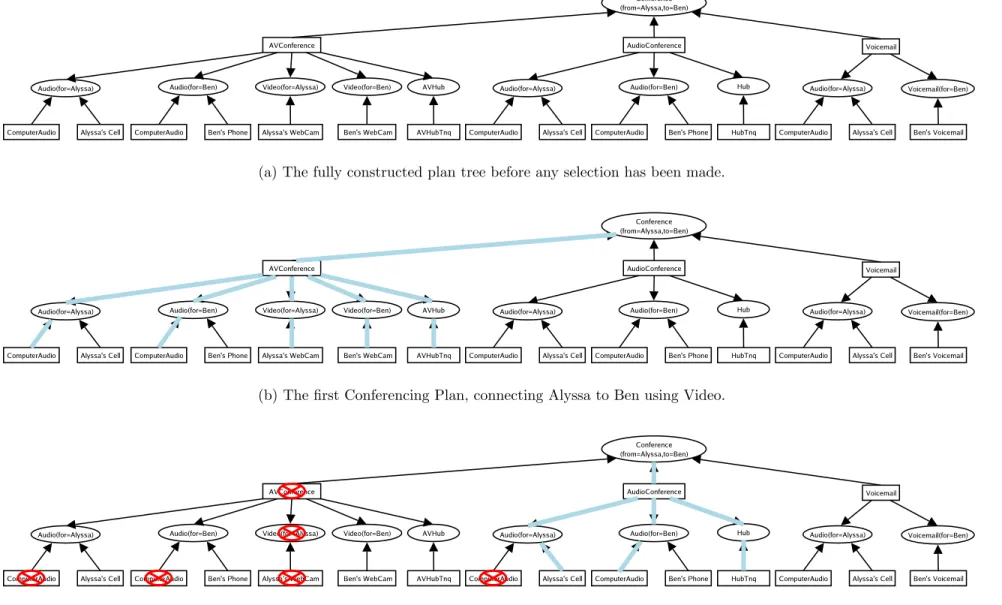
In order to solidify the concepts of the Goal-oriented paradigm, consider the Con-ferencing task of the introduction. Figure 2-1 illustrates the example. In the goal-oriented system, the entire Conferencing task is represented by the Goal Instance Conference(from=Alyssa, to=Ben). When Alyssa requests satisfaction of this Goal,
her Planner will try to find Techniques that satisfy the Goal Instance. In this
case, it finds AVConference, AudioConference, and Voicemail and instantiates these Techniques with the parameters {from=Alyssa, to=Ben} to form three Tech-nique Instances. In Figure 2-1(a), these form the second level of the plan tree. Each of these Technique Instances specifies subgoals based on its parameters. The
(a) The fully constructed plan tree before any selection has been made.
(b) The first Conferencing Plan, connecting Alyssa to Ben using Video.
(c) The second Conferencing Plan, initiated after Alyssa leaves her office. Note that several Techniques have failed, and as a consequence new ones were chosen.
Figure 2-1: Stages of a Goal-oriented Teleconference
for Ben, and a Hub. The Audio subgoals provide duplex audio, while the Hub connects the audio streams together. The Planner continues recursively constructing the Plan Tree until it bottoms out at Technique Instances with no sub-goals.
Once the tree has been built, the Planner will decide which Plan in the Plan Tree best satisfies the Conference Goal Instance. Assume that initially, Alyssa and Ben both have duplex audio and video connections on their computers and they are both in their offices. The Planner realizes that it can use these resources so it executes the Plan of Figure 2-1(b).
The Planner continually monitors its executed Plan. Suppose Alyssa leaves her office. After leaving, she no longer has video capabilities and her audio capabilities are limited to her phone. This causes her ComputerAudio and WebCam Techniques In-stances to fail. As a consequence, the AVConference’s subgoal of Video(for=Alyssa) is no longer implementable, so the AVConference Technique Instance itself fails. The Planner recognizes this and chooses the next best implementable option: fail-over to the AudioConference Technique Instance using Alyssa’s phone for her audio connec-tion and Ben’s computer for his. Figure 2-1(c) shows failures and the new Plan.
Finally, when either Alyssa or Ben decides to cancel the conference, the Planner shuts down all active Techniques Instances and garbage-collects the Plan Tree.
Chapter 3
Related Work
Related work falls into roughly five categories: make, multiple dispatch, ai Planning, heuristic search, and other pervasive computing systems.
3.1
make
Many people immediately think of make [11] when they first hear about Goal-oriented programming. This is because make seems to implement goal satisfaction: the com-mand make file.o will result in the object file.o being created if there is some rule that can make file.o and if all of that rule’s preconditions are met. Roughly, a Goal would correspond to the actual make command, Techniques to the Makefile rules, and Technique subgoals to rule preconditions. Some have even called this goal-oriented programming and have proposed make-like distributed systems [17].
However, our model differs significantly. First, we allow true separation of intent and implementation. A Goal Instance may be satisfied by zero or more Technique Instances whereas a Makefile rule has exactly one body. Moreover, since each Goal may be satisfied by any one Technique, our dependence graph is an and-or tree rather than make’s less flexible and tree. Second, make’s rules are not parameterized, so any variation in rules can only be achieved by creating many similar, but distinct rules. Finally, and most importantly, make is not adaptive. When make runs, it either completes successfully or fails if any dependency fails. Goal-oriented programming,
on the other hand, tries to maintain its goal in spite of failures of dependencies.
3.2
Multiple Dispatch
Satisfaction of a Goal Instance is close in spirit to a generic function call in a multiple dispatch language [3, 2, 6]. Multiple dispatch languages are a generalization of com-mon object oriented languages. Instead of letting the first argument (the object) of a procedure determine the what function body will process the call, all of the arguments are treated equally. Hence, a function dispatch must go through a phase of arbitra-tion where the runtime types of the arguments to the funcarbitra-tion are evaluated and a function chosen. The Plan evaluation phase is analogous to this arbitration phase but with one large difference: in a Goal-oriented system, each Technique Instance evaluates the arguments to determine its own ability to satisfy the Goal Instance, and, as such, contributes to the arbitration process.
3.3
Planning in the ai Community
Planning and goal resolution are two long standing problems in the Artificial Intel-ligence community. Indeed, there are several downloadable planner implementations as well as many concrete applications, such as in nasa’s space program [18].
Most planning solutions are based on the strips model [10]. The strips model was developed to plan the ordering and choice of actions of a robot as it accom-plishes some task. strips operates on world models—sets of known facts about the environment—and satisfies a goal by applying operators to a series of world models in an attempt to find a final world model where the goal is satisfied. Each operator acts on a starting world model and produces a new world model incorporating the operator’s changes. If a strips planner can find an ordering of operators that take the initial world model to the final one, then the goal is achieved.
Interestingly, in their 1971 paper on strips, Fikes and Nilsson wrote “...we would like strips to be able to generate computer programs,” [10] anticipating that
style planning could be used to tie together primitive software operators to make a larger software system. However, even given this forshadowing, it was many years before planning was applied to software constrution. In the early 1990s, a group at the University of Washington created a strips-based software robot[8, 9], or softbot for short. The softbot knew how to interact with unix to solve a variety of tasks,
such as keeping LATEX and postscript files in sync or locating a person by searching
through network databases.
Goal-oriented programming aims to solve what we believe is a different problem. strips and ai planners try to find an ordering of actions that can create the envi-ronment it needs to achieve a goal. Goal-oriented programming, on the other hand, simply searches the environment for its dependencies. Whereas an ai planner may try to build complete solutions to a problem, Goal-oriented programming can only aggregate smaller solutions. While this seems simpler, we are unsure if it is provably so.
3.4
Heuristic Search
Many ai applications, such as theorem proving, employ a variety of algorithms and heuristics to speed up search in a large problem space. This research is directly applicable to Goal-oriented programming since the Planner must search through the set of all Plans in the Plan Tree to find the Plan it eventually executes.
Prolog [16] is a language designed to address such applications. Prolog matches its current goal to the set of rules it has. Then it expands the body of the rule to create more goals that need to be solved. A goal can be achieved if the search bottoms out a some set of base rules. Prolog will backtrack if a goal cannot be achieved. This nearly matches our goal resolution methodology and influenced our current implementation. More recently, ai researchers have turned to sat solvers for quick search solutions. For example, strips planning problems have been compiled to boolean satisfiability problems [18]. After compilation, the Planning problems are fed to sat solvers like BlackBox [12]. The sat community has produced such incredibly fast solvers that
many “compile-to-sat” planners are significantly faster than hand-tuned planners. Goal-oriented programming might similarly benefit from having a sat engine as its backing algorithm.
3.5
Recent Systems Developments
Finally, the systems community has been actively exploring application programming in pervasive and Internet environments. For example, service composition projects try to build frameworks for tying together several distributed systems to perform some greater service. HP’s eFlow [4] attacks the problem of re-composing a running service or even an entire class of running services. Specifically, eFlow creates a pro-gramming interface that is easy to reason about. The Planner of a Goal-oriented system must be similarly able to reason about change and be able to export some implementation-modification api that Technique writers can easily understand and implement. However, unlike eFlow, which requires all service changes to be created by a programmer, the Planner must be able to make such changes automatically using information from Technique Instances.
A few projects even integrate aspects of ai planning into their composition engines. One example, DReggie [5] uses a Prolog-based planning engine to discover services in a changing mobile environment. The Prolog engine helps DReggie find service providers that match ranged constraints as well as others that come close to matching the constraints. Such an engine may be helpful during the construction phase of Goal planning. Unfortunately, DReggie does not tackle the problem of actually composing the discovered services.
Additionally, there are many pervasive computing projects that have goals similar to this project. For example, the Aura Project [1] at Carnegie-Mellon also sepa-rates user intents from implementations of intents in order to create a framework for adaptive applications. However, it only matches pre-defined implementations to user intents. The Goal-oriented system of this thesis goes one step further and allows the implementations—Techniques—declare subgoals.
Chapter 4
Design Challenges
In the design of a Goal-oriented system, there are two linked design spaces. The first is the api that Techniques must implement in order to be used by the system. The second is the environment that the Planner creates for Techniques. Both play off each other and center around a trade-off of giving Techniques maximum flexibility while simultaneously enabling reasonable implementations of the Planner. This trade-off must be deliberate since a Goal-oriented system will only truly thrive if Techniques can be used with many generations of Planners.
To guide our design, we kept to a few key design principles:
Ease of Programmer Reasoning Programming in a pervasive environment is al-ready difficult since the programmer must keep track of asynchronous events and changing network conditions while ensuring that application logic is correct. Since we do not want to make this situation worse, a Goal-oriented system must make it as easy as possible for the programmer to correctly write application logic as well as providing the simplest interfaces possible to handle events and other requests.
Separating policy from mechanism Techniques provide templates for Goals, and as a consequence, as many policy decisions as possible should be made in these templates. The Planner’s should strive to provide mechanism only to connect Techniques. Occasionally, however, the Planner will need to make decisions
about the Technique Instances. For example, the Planner needs to choose which Technique Instance will be chosen to satisfy a Goal Instance. Since such a decision, and others like it, fundamentally alter the way a Goal Instance is satisfied, the Planner should provide a way to customize the policy or leave it completely to the Techniques.
Isolation of Planning mechanism from application logic and Techniques This ensures that development of the Planner, applications, and Techniques can progress independently. In particular, this design principle means that we do not assume any particular Planner implementation or evaluation algorithm. Given information about all of the Techniques, a Planner is free to implement any path of the tree. This way, we can plug-in ai planners or theorem-provers in our system.
Simplicity Overall, we would like our system to be as simple as possible so that there are fewer parts to understand, fewer guarantees that need to be met, and fewer restrictions on optimization. For example, when deciding what policy decisions the Planner must force on Techniques, we need to consider how much simpler or more complex it forces Techniques to be.
The rest of this section describes some of the challenges associated with the Tech-nique and Planner architectures. First, we delve more deeply into the Goal-Oriented Conference example in order to better understand the challenges involved in Planner and Technique interaction. Then for the remainder of the chapter, we identify and explore the challenges in each phase more deeply.
4.1
A Typical Planner/Technique Interaction
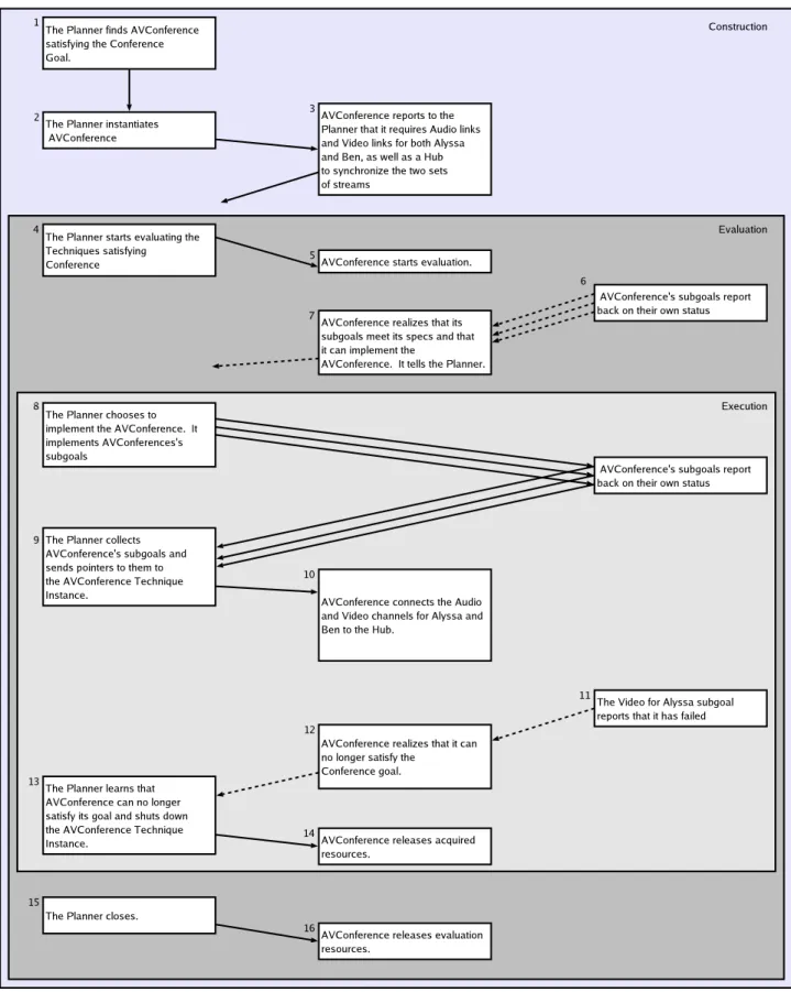
All of the components in a goal-oriented system must support the three phases of goal resolution: construction, evaluation, and execution. Figure 4-1 shows the interactions that the AVConference Technique Instance and the Planner have over the course of the example scenario.
Figure 4-1: A transcript of the interaction between the Planner and the AVConference Technique in the example scenario. Synchronous calls are represented by solid arrows while asynchronous events are represented by dashed arrows. Blocks not connected by arrows may be widely separated in time.
The Planner first interacts with the AVConference Technique after discovering that it implements the Conference Goal. In Step 2, the Planner instantiates the
AVConference Technique to create an AVConference Technique Instance with the
correct parameters. Next, in order to construct the Plan Tree, the Planner asks the
AVConferenceinstance to enumerate its subgoals. Some time later, the Planner starts
its evaluation of the Conference Goal Instance, which kicks off a variety of activity in
AVConference(Steps 4–7). Recall, in the example scenario, Alyssa and Ben are both
at their video-equipped computers, so initially the AVConference best satisfies the
ConferenceGoal Instance. Therefore, after evaluating the other Technique Instances,
the Planner chooses to execute AVConference in Steps 8–10. Eventually, Alyssa leaves her office, causing one of AVConference’s subgoals to fail, which in turn causes
AVConference itself to fail and the Planner to choose another Technique Instance.
Accordingly, AVConference’s implementation is shutdown, though it continues to evaluate its environment in case the video conferencing tools become applicable again. Finally, when the conference ends, the Planner garbage collects the AVConference Technique Instance.
4.2
Construction
As step 1 of Figure 4-1 shows, for every Goal Instance in the tree, the Planner must try to find a set of corresponding Technique Instances. Since each Technique declares
the Goal it satisfies, this amounts to a table look-up1 and instantiation with
parame-ters. However, maintaining this table presents a policy problem since the Techniques that the Planner has access to fundamentally alter the resulting implementations. Therefore, the Planner must provide a user-defined way of finding Techniques.
Similarly, the Planner must also query each Technique Instance for its subgoals and subgoal arguments. Both of these may depend on the Technique Instance’s bound parameters. For example, in step 3 of Figure 4-1, the AVConference Technique 1Note that there is no corresponding repository of Goals since each Technique can contain a
pointer to its Goal specification.
Instance needs to know that it is connecting Alyssa and Ben in order to properly enumerate its subgoals. The Planner, therefore, needs to let the Technique Instance dynamically declare its subgoals.
4.3
Evaluation
The next phase evaluates potential Plans in order to choose which Technique Instances are executed in order to satisfy each Goal Instance. Each Technique Instance provides the Planner with a self-evaluation, while Goal Instances inherit the evaluation values of their children Technique Instances. In Figure 4-1 this is the essence of steps 4–7.
Two basic considerations are the metrics used to communicate suitability for a particular goal as well as the “reach” of the metrics—how much information the metric has at its disposal when it computes its suitability. Applied to the scenario, the metric affects the form of the messages passed in steps 6 and 7. This is potentially difficult since AVConference must be able to understand the evaluation results of any Technique the Planner chooses to implement its subgoals. The “reach” of the metric affects how much information about the Plan Tree as a whole the AVConference has as its disposal in Step 7 when it decides that it can implement the Conference goal.
4.3.1
Evaluation Metrics
Fundamentally, the job of the Planner in the evaluation phase is to order all of the Technique Instances satisfying each Goal Instance so that it may choose one for execution. Choosing a correct metric is important since the metric shapes how the Goal Instance is satisfied. For example, one Goal Instance that provides video links may favor Technique Instances providing high bandwidth links, while another Goal Instance may favor Technique Instances providing low latency links. The evaluation metric should allow the Goal Instance to discern between these to kinds of links and choose what it wants.
To aid in Technique Instance selection, evaluation information may flow both up and down the Plan Tree. For example, a Technique may want its subgoals to succeed
if and only if they meet some expectation. This is a case for passing evaluation information down the tree. Another Technique may be able to cope with variability in its subgoals, and as such is interested when they change how well they satisfy their Goal Instances. Since subgoal variability may change how well the Technique Instance itself can satisfy its Goal Instance, evaluation information flows up the tree. Some Techniques may even use a combination of both flows. This is particularly useful in the example scenario since the AVConference Technique could specify video links limited by a maximum latency, but with variable quality. Since both top-down and bottom-up evaluation styles are valid policies, the Planner must strive to support both.
Finally, while the Technique may employ a variety of policies to judge its suitability to a particular goal, these policies are useless if the Planner cannot interpret the final result of the Technique Instances’ evaluation. For the Goal-oriented system to work correctly, either the Planner needs to understand all possible evaluation methodologies or all Techniques must conform to a particular Planner-imposed standard.
4.3.2
Evaluation Reach
Suppose that we do have a way for Technique Instances to communicate how well they satisfy their Goal Instances. A remaining unanswered questions is how information the Planner may use when evaluating an entire Plan.
There are two fundamentally different ways of evaluating a Plan. One is to eval-uate entire paths through the Plan Tree and choose the “best” path based on the Techniques’ metrics. A second is to evaluate each node in the tree and make local decisions as to what is best.
Largely, the evaluation methodology the Planner uses is an implementation detail. Moreover, our Isolation design principle implies that we shouldn’t specify any con-straints on the Planner’s Plan evaluation phase. However, evaluation methodology becomes a design issue when Goals may be specified in such a way that they depend on the evaluation method of the Planner.
At first glance, it seems that the path-based evaluation may lead to better plans 32
since Technique Instances at the end of the path may make up for deficiencies in Tech-nique Instances at the beginning of the path. However, there are some disadvantages to path-based evaluation. Since the suitability of a particular Technique Instance may change rapidly in time, it is difficult to pin down an entire path of Technique Instances for evaluation. Furthermore, this evaluation method may add complexity to the evaluation phase, violating our simplicity design principle. We also expect many Planners to make greedy decisions at each Goal in the tree since greedy algorithms are easy to implement. Therefore, the design of the Planner must restrict evaluation in some way that allows both simple implementations as well as more complicated ones.
4.3.3
Changing Evaluation with Time
As exemplified by step 11 in Figure 4-1, Technique Instances can change their reported ability to satisfy their Goal Instance at any time. This can be due to both external events and changes in its subgoals. Therefore, the Planner must support a way for Technique Instances to respond to evaluation events and notify of the Planner any changes it makes.
4.4
Execution
As step 9 of Figure 4-1 shows, once a Plan has been chosen, the Planner must execute the Technique Instances in the Plan starting at the bottom. Starting at the bottom is necessary because Technique Instances depend on their subgoals to satisfy their own Goal Instances.
After execution, each Technique Instance must be able to handle events from its subgoals. These events may be implementation-altering events, such as the swapping of subgoals, or more mundane management events, such as a signal that the Technique Instance should quit and shutdown its executing code.
4.5
Error Handling
The execute phase is the commit point for a Technique Instance. All information in the Construction and Evaluation stages is tentative because the Technique Instance is only estimating what resources it needs or how well it can meet its Goal Instance. However, only when the Technique Instance is actually executes will the estimates be proved right or wrong. For example, the AVConference might run into problems connecting its Video subgoals together. Moreover, as Alyssa’s leaving her office in step 11 shows, even if the Technique Instance successfully executes initially, at a later time it may no longer be able to satisfy its Goal Instance. Therefore, the Planner must be able to react to failures in the execution phase.
Chapter 5
Design
Given the challenges of the previous chapter, any architecture for a Goal-oriented system must provide:
1. a way to find Techniques,
2. a way to evaluate them uniformly,
3. an environment for executing Technique evaluation and execution code, 4. methods for Technique Instance-Planner interaction, and
5. a way for Technique Instances to respond to events.
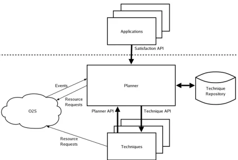
Our architecture for providing these services is illustrated in Figure 5-1. The archi-tecture separates Technique Discovery from the rest of the Planner, then concentrates on the interactions between Techniques and the Planner. These interactions are cod-ified by a Planner api and a Technique api. Finally, the architecture also provides a Satisfaction api that applications use to access the Planner.
5.1
Simplifying Assumptions and Clarifications
In order to concentrate on the dynamics of the evaluation and execution phases of the Goal-oriented system, we make a simplifying assumption that the construction phase completes before any part of the plan tree starts its evaluation phase.
Figure 5-1: Illustration of the Goal-oriented programming system’s architecture.
Furthermore, we assume that the Planner and its Techniques operate in an envi-ronment much like that of the O2S System. That is, both the Planner and Techniques may assume that there are resource discovery, remote resource invocation, and asyn-chronous event handling services inherent in the operating environment. This also means that the Planner itself must support these operations. We allow both the Tech-niques and the Planner make synchronous requests on the outside world. However, in order to have control over the Technique execution, only the Planner can receive asynchronous events and callbacks. This way, the Planner can serialize all events, and schedule event callbacks for execution when it makes the most sense to.
5.2
Technique Discovery
Keeping with our design principle of separating policy from mechanism, the Planner offloads technique discovery to a user-controlled Technique Repository. This repos-itory contains only the Techniques that the Planner can and should access. A user can customize the Techniques her Planner sees by altering the contents of her reposi-tory. Additionally, adding a level of indirection for technique discovery helps with the
fourth design principle of simplicity since the Technique Repository can implement complicated caching or security independent of the Planner.
5.3
Satisfaction: A Uniform Evaluation Value
As reviewed in Section 4.3, to allow arbitrary Techniques to interoperate with gener-ations of Planners, either the Planner must understand all Techniques, or the Tech-niques must speak a common evaluation protocol with the Planner. We believe the latter approach is simpler and in many cases as expressive as letting Technique define their own evaluation protocol.
Therefore, we require that each Technique render all evaluation decisions into a single scalar we term satisfaction. The higher the satisfaction, the better a Technique Instance can implement its Goal Instance. A satisfaction of 0 indicates that the Technique Instance cannot satisfy the Goal Instance at all. What other values mean is determined by each Goal and codified in the Goal specification. Thus, satisfaction is an evaluation metric mechanism that: can be passed up the tree, allows for Goal-specific policy, and has simple semantics that both the Planner and the Technique programmer can understand. All of these properties are in line with our design principles.
The satisfaction metric also enables a simple, policy-independent way of pushing evaluation information down the tree. A Technique Instance need only specify what it expects as the arguments to its subgoals. If the Technique Instances fulfilling the subgoal cannot meet expectations, they report back a satisfaction of 0. If they can meet expectations, they report back a non-zero satisfaction and the Planner chooses among the satisfactory Technique Instances.
In order to allow for particularly simple Planners, we require that Goal specifica-tions, and thus, Technique Instance evaluaspecifica-tions, be workable with a greedy algorithm that works on only one Goal at a time. In other words, a Technique Instance’s eval-uation can only depend on its subgoals’ satisfaction and whatever other evaleval-uation information the Technique Instance can generate. To enforce this, the Planner will
only report to the Technique Instance the satisfaction levels of its immediate subgoals. Finally, each Planner can set its own policy on how to determine the satisfaction of any given Goal Instance. We impose only two contraints on the Goal satisfaction level. First, a Goal Instance with no satisfactory Techniques must have a satisfaction of 0. Second, the Goal Instance’s satisfaction level must be consistent with the Goal’s specification.
Some may argue that the Planner-imposed satisfaction system violates our design principle of separating policy and mechanism. The argument is based on a common need to express how well a Technique Instance may perform on orthogonal issues. This is a valid criticism since a general evaluation method may not compress into a single metric. However, we rely on the heuristic that in most evaluations there is some final decision that sways the evaluation one way or another. The particular use of the satisfaction metric in the Goal specification can reflect this final binary decision. While having to specify such decisions in the Goal specification may com-plicate specification writing, we believe the trade-off for policy-independence is worth it. Moreover, we believe that satisfaction also ports to ai theorem-proving systems, making the trade-off even more valuable.
5.4
The Planner api
The Planner api provides a set of functions aimed at enabling inter-Technique In-stance and Planner-Technique InIn-stance communication. These functions are shown in Figure 5-2. Only the first three functions are needed by the Planner: these allow a Technique Instance to pass information to and through the Planner. The remaining functions are convenience functions that help a Technique integrate into a pervasive environment.
The send event function is used to send an event between executing Technique Instances. The to argument can either be "parent" or the name of one of the Technique Instance’s subgoals. This function is provided to strengthen the subgoal abstraction since the Technique Instance should only be able to control its subgoals by
Communication Functions: send event(to, event) post(event)
signal quit() Pervasive Functions:
find resources(profile) returns set of resources
add subscription(profile) returns subscription id
remove subscription(subscription id) monitor resource(resource)
unmonitor resource(resource)
get event listener() returns listener resource
Figure 5-2: Planner api used by Techniques
name. post is used to inform the Planner of changes in satisfaction or the return value of the Technique Instance. Finally, the signal quit function notifies the Planner that the Technique Instance would like to quit normally. signal quit should only be used for normal terminations. Section 5.5.2 describes Technique event generation in more detail.
The first block of pervasive helper functions allows the Technique Instance to discover resources. Specifically, the find resources returns a possibly empty set of resources matching the given profile. The next two manage callback subscriptions that allow the Technique Instance to be notified if new resources come into the environ-ment. The callback messages are received by the Technique Instance’s handle event method.
The next block of functions allows the Technique Instance to monitor the health of a resource. Like resource subscriptions, resource health notifications are received by the Technique Instance’s handle event method.
Finally, there may be other kinds of event callbacks that the Technique Instance may want to register, many of which are application-specific. The get event listener function returns an event listener. Any event sent to this event listener will be queued to be received by the Technique Instance’s handle event method.
Constructor(planner, arguments) Construction Functions:
get subgoals() returns map of names to subgoals
Evaluation Functions: start evaluation() stop evaluation() Execution Functions:
start execution(subgoals) returns handle
stop execution()
Event handling Functions: handle event(event)
Figure 5-3: api for Techniques
5.5
The Technique api
Figure 5-3 shows the api that Techniques must implement. Techniques need not be thread-safe as the Planner guarantees that the Technique is executing in at most one thread at any given time.
When the Planner instantiates a Technique, the Planner gives the Technique both
its arguments and a pointer to itself. The resulting object is a Technique Instance1.
The Planner pointer enables the Technique to access the Planner api. The Planner also passes the arguments of the Goal Instance for which the Technique is being in-stantiated since the Technique will need to make decisions based on those arguments.
5.5.1
Phases of Goal Resolution
During the construction phase, the Planner calls each Technique’s get subgoals function. The Technique returns a set of name, subgoal pairs. In all subsequent stages of Goal resolution, the Planner will refer to the subgoals by the names the 1In this section, we will primarily refer to Techniques rather than Technique Instances. This
is because programmers write Techniques that are instantiated by the Planner into Technique In-stances.
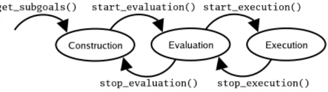
Figure 5-4: Each function call the Planner makes moves the Technique into a different phase.
Technique chose.
When the Planner determines that the Technique should enter the evaluation phase, it calls start evaluation. Here, the Technique can send to the planner a basic estimate of its satisfaction as well as register relevant network probes.
When the Planner chooses a Technique for execution, it calls start execution with the return values of the Technique’s subgoals, using the same names that the Technique chose earlier. The exact type of the value bound to each subgoal name is determined by the Goal specification that the subgoal implements. During this call, the Technique should acquire any resources it needs. If the initialization succeeds, the start execution function returns a handle as dictated in its Goal specification. Otherwise, the start execution call fails by returning a special FAIL return value to the Planner. The Technique returns to the Evaluation phase and the Planner makes alternate plans if possible. If the Planner decides to shutdown an executing Technique, it calls the stop execution function on that Technique. The Technique must release all of the resources that it reserved.
Finally, if the Planner decides that certain Techniques are taking too many evalu-ation resources, it may call stop evaluevalu-ation. In this call, the Technique must cancel any callbacks it started in the start evaluation function.
The Planner calls Technique methods in “Goal resolution” order as Figure 5-4. In particular, get subgoals, start evaluation, and start execution must be called to move the Technique into the construction, evaluation, and execution stages, respectively. Similarly, stop evaluation and stop execution are used to take the Technique out of the evaluation and execution stages. These guarantees are made so that the Technique knows what plan phase it is in so that it can handle events
Planner Functions:
Constructor(technique repository, event listener)
satisfy(goal, goal args, event listener) returns Plan object
stop()
Plan Functions: stop()
Figure 5-5: The Satisfaction api the Planner exports to Applications. properly.
5.5.2
Event Handling
At any point after instantiation, the Planner may call the Technique’s handle event function. Typically, the events passed to this function are callbacks from sub-goals or parent Techniques, though they may also be callbacks from the event listener the Technique has access to. Any events from subgoals are identified by the name of the subgoal given to the Planner in the construction phase.
The Planner defines two kinds of Events that it understands. Techniques send these messages using the post method of the Planner’s event system. The first is the EvaluationCallback message, which carries with it an update to a Technique’s satisfaction. The Planner will then take this into consideration and pass the value up the tree as necessary. If a Technique needs to report that it can no longer solve its Goal, it sends an EvaluationCallback message with satisfaction set to 0. The other message is an ExecutionCallback, which returns the result of re-implementing part of the executing plan tree.
5.6
Satisfaction api
In order to separate development of applications from development of the Planner, the Planner’s Goal Satisfaction api must be standardized. Figure 5-5 shows the api the Planner exports to applications. The most important function is the satisfy call, which instructs the Planner to satisfy some Goal Instance. It returns a Plan object,
which is a handle to that specific satisfaction call. One Planner can satisfy many Goal Instances at once. Both the Planner and the satisfy call can optionally take in event listeners, which will receive status events. For example, a Plan object may notify the event listener whenever it changes its underlying implementation. Both objects export a stop method. The stop method is used to cleanly shutdown the Plan or Planner as a whole. Finally, the Planner also takes in a Technique Repository that it will use as its database of Techniques.
5.7
Goal-oriented Conferencing Revisited
Figure 5-6 shows the interaction between the Planner and the AVConference Tech-nique Instance using our api. There are a few things to note. First, the Planner always uses the names of the subgoals that the Technique Instance returns in step 3. Instances of this can be seen in steps 6, 9, and 11. Second, there are no direct calls between the Technique Instance and its subgoals, or from the Technique Instance to its super-goals. Such interactions are provided through the handle event and post method calls. This way, each Technique Instance is isolated from all other Technique Instances. Finally, the ordering of method calls on the AVConference object helps the Technique Instance know what execution stage the Planner is in. This way, the
AVConference can handle the events of steps 6 (received when evaluating) and 11
Figure 5-6: The sample interaction between the Planner and the AVConference Tech-nique Instance annotated with the api calls that each makes. p is a reference to the Planner planning the Conference goal. avc is a reference to the AVConference Tech-nique Instance created in step 2.
Chapter 6
Implementation
We implemented a basic Planner and several Techniques based on our Goal-oriented programming system design. Our implementation was written in Python 2.3 [15]. We chose Python mainly because the rest of the O2S environment is written in Python. No code of the Planner depends on a special feature unique to Python and could have been implemented in Java or any other object-oriented language supporting xmlrpc (to support communication with the rest of O2S). The implementation runs under GNU/Linux, Windows using Cygwin, and Mac OS X.
There are two main goals for this implementation. The first is to prove that the proposed api of the previous chapter is workable. The second is to exploit as much parallelism as possible in the Planner. This helps show that the proposed api lends itself to optimization as well as allowing large plan trees to be evaluated and implemented quickly.
6.1
Writing a Parallel Planner
For our Planner implementation, we chose to try to exploit as much parallelism as possible. This is motivated by the fact that Techniques do not do much computation, but rather connect together Resources. Since many of these connections happen over a network, most of the time a Technique is blocked waiting for a response. In a serial Planner, this could lead to serious performance problems. For example,
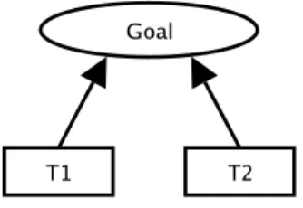
Figure 6-1: Simple Plan Tree. If T 1 takes a long time to evaluate, in a single-threaded Planner, T 2 will be blocked.
consider the simple plan tree of Figure 6-1. Suppose that Technique Instance T 1 makes many network requests to determine its satisfaction and takes 5 seconds to post a satisfaction of .25, while T 2 takes far less time to post a better satisfaction of .5. A single-threaded Planner can take 5.25 seconds to choose T 2 when it should take closer to .25 seconds. It is easy to see that adding Technique Instances only makes the problem worse. However, a multi-threaded planner could run the two Technique Instances in parallel and have more of a chance of approaching the lower
bound of .25 seconds.1 Similar problems also plague event dispatch to Techniques.
In a single-threaded Planner, one Technique Instance could block event dispatch to other Technique Instances if its handle event function takes sufficiently long.
In order to avoid these performance problems, we chose to implement a multi-threaded Planner that runs as much of the planning process in parallel. Our Goal-oriented system architecture anticipates that some Planners may be multi-threaded and as such, ensures that distinct Technique Instances only communicate with each other though asynchronous events. Since we don’t need to worry about isolating Tech-nique Instances from each other, the main difficulty in our implementation becomes efficiently parallelizing the Planner while at the same time ensuring that a Technique Instance is never called in more than one thread at a time.
A Technique Instance may be called by more than one thread because its handle event method may be called any time after object construction. The obvious solution is to wrap a lock around each Technique Instance and block operations on Technique Instances that are already running. However, this imposes scheduling problems when 1Note that if T 1 had a higher satisfaction than T 1, parallelism is still helpful since we could more
quickly get a worse solution with T 2 and then swap T 1 for T 2 when the Planner learns that T 1 is better.
a single Technique Instance may get many events at once, since the Planner may schedule all of its threads to servicing those events, essentially leading to a livelocked state. A potential refinement of this scheme is to give each Technique Instance its own event queue and schedule it to handle all of the events in the queue. This has a fairness problem since a set of Techniques with many events may take up all available worker threads servicing their event queues, starving other threads of computation time.
Therefore, we eschew fine-grained locking for the coarser mechanism of thread coloring. The Planner assigns each Technique Instance in the tree a unique color. During runtime, each worker thread assumes the color of the Technique Instance it is working with. The Planner makes sure that no color is running in more than one thread at any given time. Clearly, such a system allows each Technique to run in only a single thread at any time. However, it also solves the fairness problem: the Planner can schedule each call to handle event separately, breaking up large computation blocks so other Techniques can run.
6.2
Physical Code Structure
Physically, the Planner code is broken into three Python modules mirroring our de-sign.
techniques Prototypes for user-defined Techniques and Goals. Contains a Technique interface and the GoalDescription class. This module provides templates for programmers.
planner The bulk of the Planner. Contains the Planner, Plan, GoalNode, and
TechniqueNode classes. This module encapsulates our specific planner
imple-mentation and related files.
event driven The parallelizing framework. Contains the EventFramework class and currying functions.
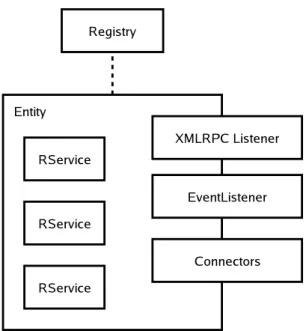
Figure 6-2: The runtime environment of O2S.
All of the interesting implementation is in the planner and event driven mod-ules. The event driven module implements a stand-alone multi-threaded event-driven framework [14, 19]. It has no dependencies on O2S, and as such may be used in other projects. The Planner of the planner module implements a simple Technique selection algorithm. Both parts are described in more detail later in this chapter.
6.3
The O2S Programming Environment
Before delving in the details of the Planner’s implementation, it makes sense to briefly review the O2S programming environment. Figure 6-2 illustrates the major runtime-structures of O2S. All Resources are concrete subclasses of RService. Resources run within an Entity object. The Entity provides Resources with an xmlrpc listener as well as an EventListener. The former allows the Resource to receive function calls over the network while the latter lets it receive asynchronous Events. For performance reasons, the xmlrpc listener will optimize out network calls if two objects share a process on a local machine.
Additionally, an Entity registers with the O2S Registry. The O2S Registry is 48
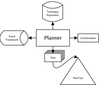
Figure 6-3: The runtime structure of the Planner.
a simple resource discovery and health monitoring system. The Registry also offers a subscription service that allows registered Entities (and the Resources contained within them) to receive events when suitable Entities come up and go down. The Planner’s resource functions are based on this interface, and in our initial implemen-tation, the Registry backs these calls.
Usually, a programmer will create an Entity:
1. when the Entity needs to be located through the Registry, or 2. when the Entity serves as a database of related Resources.
Typically, Entities act as proxies for some host or user. Almost all other functionality is coded as Resources.
6.4
Runtime Code Structure of the Planner
Figure 6-3 shows the runtime structure of the Planner. One Planner object contains a reference to a TechniqueRepository, an EventListener, an EventFramework, and zero or more Plan objects. Each Plan object represents a user-initiated goal call. The TechniqueRepository contains the database of Techniques the Planner should access, while the EventListener is an O2S event listener that enables the Planner
to receive O2S events. The EventFramework provides a loop that drives the Planner and is discussed in more detail in Section 6.5.
In our current implementation, the main job of the Planner object is to run the main EventFramework loop, serialize O2S events, and support the Planner half of the Satisfaction api. Most of the algorithmic logic for goal resolution is embedded in the
Planclass and the PlanTreeNodes it contains. The Plan object also implements the
Plan half of the Satisfaction api, as well as the Planner api exported to Techniques.
6.4.1
The Plan Object
Each Plan object contains all of the necessary state to satisfy a user-initiated Goal. In particular it contains a tree of PlanTreeNode objects that represents the Goal tree. PlanTreeNode is an abstract O2S RService with two concrete sub-classes,
GoalInstance and TechniqueInstance, which are instances of Goals and
Tech-niques, respectively. PlanTreeNode contains mostly mechanism related to O2S, while its concrete sub-classes implement the Goal-selection algorithm.
The PlanTreeNode Class
The PlanTreeNode provides the Planner api interface of Figure 5-2.
PlanTreeNodeinherits from O2S’s RService class and as a result, can be passed as
a Resource. In particular, the PlanTreeNode class implements the O2S EventListener Resource specification. One bookkeeping job the Planner must perform efficiently is routing of Events through the Planner’s one EventListener. Since each PlanTreeNode is directly corresponds to a Goal or Technique Instance, if the PlanTreeNode is passed, it knows which node the event goes to, and as a result can multiplex the Planner’s EventListener without keeping lookup tables. This significantly simplifies the Planner object’s implementation.
The GoalInstance Class
The GoalInstance class implements a very simple algorithm for Goal selection. On initial evaluation, the GoalInstance chooses the TechniqueInstance with the high-est satisfaction for implementation. This choice is made either after all TechniqueInstances have reported their satisfaction or a timeout occurs. Note that as long as TechniqueInstances correctly calculate their satisfaction, this choice is in line with our requirement that
Planners choose a Goal satisfaction in line with the Goal specification. The GoalInstance updates its choice as TechniqueInstance satisfactions change: it always tracks the most satisfying TechniqueInstance and keeps the satisfaction value of that best instance.
The TechniqueInstance Class
The TechniqueInstance class is a thin wrapper around a Technique. It only adds functionality around the Technique’s handle event function. Specifically, it trans-lates the from field of the event from the GoalInstance object itself to the name of the Goal specified by the Technique’s get subgoals function.
6.5
The EventFramework
The EventFramework contains all of the code to implement our thread coloring system as well as the api of Figure 6-4. The api is loosely based on that of libasync-mp [20, 7]. As its name suggests, the EventFramework centers on “events” that it reads from an event queue. Each event contains at the least a function pointer and a color. The function pointer is executed when the event is serviced while the color is used for thread coloring. The EventFramework ensures that no two events of the same color are serviced at the same time.
The first two functions in the EventFramework api schedule functions. enqueue and run both create events that run their fn argument; run also calls creates an event that runs cb when fn completes. The next two functions manage time-delayed callbacks, typically used to implement timeouts. The delay cb function will cb at
Call Scheduling Functions: enqueue(fn, color)
run(fn, cb, color, cb color)
Delayed Execution Management Functions:
delay cb(cb, delay, color) returns callback id
remove cb(callback id) Function Currying for above:
curry(fn, arguments...) returns closure
Callback Functions: post(poster, message)
register post callback(cb, filter, poster, color) returns reg id
unregister post callback(reg id)
Figure 6-4: api exported by the EventFramework.
least delay seconds after the delay cb call. remove cb allows delayed callbacks to be removed before they are run. Function arguments to all of the above calls must be argument-less. As a convenience, the curry function turns the application of fn to its arguments into a parameter-less closure that can be used by the other functions. Finally, the last three EventFramework methods allow Techniques to post messages and register callbacks to receive those messages asynchronously.
6.5.1
Implementation of the EventFramework
Figure 6-5 shows the major components of the EventFramework. Events scheduled by delay cb contain delay times, while events scheduled by run also contain callback functions and colors for the callbacks.
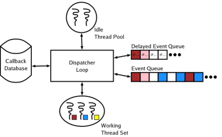
The heart of the Event-Driven implementation is the Dispatch Loop. Its job is to assign events from the Event Queue to idle threads in its thread pool. It also monitors the Delayed Event Queue and adds events to the main Event Queue when the delay has expired. Finally, the Dispatch Loop also manages messages and callbacks from produced by the post calls. The Dispatch Loop is responsible for ensuring that only one color runs at any given time and also that for any given color, events run in fifo order.
Figure 6-5: The runtime structure of the EventFramework.
The rest of the implementation is straightforward. When assigned an event, a worker thread runs the function, and schedules the event’s callback (if it has one) when the function completes. When it completes, the worker thread returns to the idle thread pool. The CallbackDatabase maintains a mapping between post callback registrations and subscription ids so that post messages can be routed to the correct callbacks.
Chapter 7
Performance Evaluation
A good goal-oriented system must provide a reasonable programming environment as well as decent performance at runtime. Therefore, we evaluate our Planning system in two ways. First, we detail a few anecdotes from development of Techniques in our Conferencing scenario of earlier chapters. Second, we evaluate the planner’s runtime performance using a variety of simulations.
7.1
Scenario Anecdotes
To support the Conferencing scenario, we created six Goals and nine Techniques. The Goals and Techniques correspond directly with Figure 2-1. We were able to write and debug the all of the Techniques in a single day. As a show of how much mechanism the Planner hides, the complete application code fits in the five lines of Figure 7-1.
The satisfaction metric works well in the Conferencing scenario: it provides a clear ordering of Techniques as well as a method of indicating failure. Additionally, we were
1 p l a n n e r = P l a n n e r ( t e c h n i q u e d b , 2 a p p e v e n t l i s t e n e r ) 3 p l a n = p l a n n e r . s a t i s f y ( c o n f e r e n c e g o a l , 4 f r o m u s e r=” A l y s s a ” ,
5 t o u s e r=”Ben” )
Figure 7-1: Application code to run the scenario. technique db is a pointer to a common TechniqueRepository
able to combine satisfaction with a few Goal parameters to avoid any backtracking in our initial evaluations phases. However, it still remains to be seen if satisfaction will be useful in larger systems and if backtracking can be avoided in the evaluation phase.
As an additional anecdote, during Technique development, we found that Goal-oriented programming lends itself quite well to incremental development. For the sce-nario’s Techniques, we first implemented the simpler AudioConference before tack-ling the more complicated AVConference Technique. We made no changes to the code in Figure 7-1: all we had to do was add the new Techniques to the TechniqueRepository and re-run the Planner.
7.2
Performance
Ideally, a user should not be able to notice that a goal-oriented system is planning her application. To the user, it should appear that the application is just adapting to its environment. However, in reality, the Planner takes time to perform its operations. This shows up as latency between making a satisfy call and getting an implementation, and as lag time between changes in the environment re-implementation of the plan.
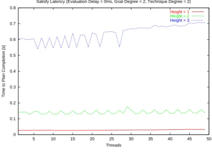
We measure performance as the amount of real time it takes the Planner to im-plement a solution to a satisfy call or re-imim-plement a solution after a change to the environment is made. We believe that this metric is appropriate because the Planner does not actually run Application or Resource code, but only glue code when im-plementations must change. For each test, the real time delay is plotted against the number of threads the Planner’s EventFramework is allowed. Since the Planner can do one operation per thread at any given time, variation in real time delay shows how well the Planner is exploiting parallelism in the tree.
7.2.1
Test Methodology
All tests were performed on a lightly-loaded Pentium 4/3.0GHz Linux workstation with 1.0GB of RAM connected to a local-area network at 100Mb/s. For each test,