Architecture and Implementation of Automation and
Scripting for Oxygen
by
Mohammad Ali Tariq
Submitted to the Department of Electrical Engineering and Computer Science in partial fulfillment of the requirements for the degree of
Master of Science at the
MASSACHUSETTS INSTITUTE OF TECHNOLOGY
May 2001
© Massachusetts Institute of Technology 2001. All rights reserved.
Author... ...
Department of Electrical Engineering and Computer Science May 11, 2001 /1)
Certified by...
Srinivas Devadas Professor of Electrical Engineering and Computer Science
Thesis Supervisor
Accepted by...
Arthur C. Smith Chairman, Department Committee on Graduate Students
MASSACHUSETTS NsTITUTE OF TECHNOLOGY
Architecture and Implementation of Automation and Scripting
for Oxygen
by
Mohammad Ali Tariq
Submitted to the Department of Electrical Engineering and Computer Science on May 11, 2001 in partial fulfillment of the
requirements for the degree of Master of Science in Electrical Engineering and Computer Science
Abstract
This thesis presents a software framework for automating simple and complex devices. This software framework consists of a user interface and a scripting engine. Special consideration has been given to creating a suitable user interface. The interface provided is a graphical user interface, which allows the user to have easy and natural access to his everyday devices. This interface enables the user to control and automate these devices. The user's automation scripts are stored and carried out as required. This thesis also discusses how this work fits into an architecture for device automation, which allows multiple devices to be networked together and automated. We also show examples of how this automation architecture can be used.
Thesis Supervisor: Srinivas Devadas
Acknowledgements
First and foremost, I would like to thank my thesis advisor, Srini Devadas, for all his help, direction and support in guiding me through the completion of my Masters thesis. He has always made himself available and has always done his best to help, even with problems I had in my personal life. He is very understanding and always has good advice to give, whatever the problem.
During my time at MIT I made a lot of very good friends. I would like to thank them all for all their support and advice in my personal as well as academic life. Especially I would like to thank Mohsin Naqvi, Smita Edulji, Sarfraz Khurshid, Raj Rao, Todd Mills and Edward Suh. We had a lot of good times and I hope to stay in touch with all of them.
I would also like to thank my family, for everything. My parents, my sister and my
brother for their support in every decision I made since I was very young. Their guidance has been invaluable to me. My wife, Marlynn, for giving me the motivation and encouragement I needed to finish on time. Without my family I would never have been able to done this.
Contents
1
Introduction ... 7 1 .1 G o a ls ... 8 1.1.1 Device Control ... 8 1.1.2 Autom ation ... 8 1.1.3 Ease of Use ... 9 1.1.4 Security ... 9 1.2 Related W ork ... 91.2.1 Cambridge Event Architecture ... 9
1.2.2 Active House ... 10
1.2.3 AutoHAN ... 10
1.3 Roadmap ... 11
2 System Architecture ... 12
2.1 Layered Architecture ... 13
2.1.1 Device Network Layer ... 14
2.1.2 Routing Layer ... 16
2.1.3 Scripting Layer ... 19
2.2 Communication between Layers ... 24
3 Im plem entation ... 26
3.1 Initialization ... 27
3.2 User Interface ... 28
3.2.1 Choosing the right interface ... 28
3.2.2 Details of the GUI ... 32
3 .3 S crip tin g ... 3 8 3.3.1 Storing Triggers and Responses ... 38
3.3.2 Receiving Events ... 39 3.3.3 Trigger M atching ... 40 3.3.4 Sending Responses ... 42 3.3.5 M ultiple Scripts ... 42 3.3.6 Killing Scripts ... 42 3.4 Device Interface ... 42 3.4.1 Sending Events ... 43
3.4.2 Determining Rooms... 44
3.4.3 Determining Device Types at a Location ... 44
3.4.4 Determining Device Names at a Location ... 45
3.4.5 Getting Device Controls and Responses for a Device ... 45
3.4.6 Getting Associated Values... 45
4 Conclusion...46
5 Appendix A - Com m and Exam ples...47
6 Appendix B - Script Exam ples... 49
List of Figures
Figure 2-1: Layer Hierarchy... 21
Figure 3-1: Architecture of Scripting Layer... 27
Figure 3-2: The Com m and Pane ... 33
Figure 3-3: The Initial Script Pane... 35
Figure 3-4: The Script Pane with two Triggers... 36
Figure 3-5: The Script Pane with a Trigger and a Response ... 37
Figure 5-1: One light bulb...47
Figure 5-2: M ultiple light bulbs ... 47
Figure 5-3: Device without Location ... 48
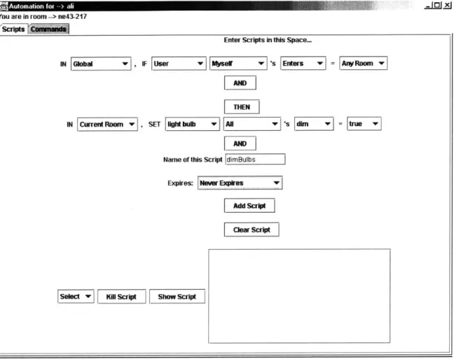
Figure 6-1: Script for dim m ing bulbs... 49
Figure 6-2: Setting A larm ... 50
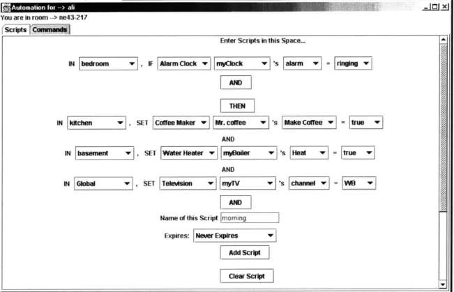
Figure 6-3: M orning Script ... 50
Figure 6-4: Sim ple Audio Script ... 51
1 Introduction
In today's world, devices exist for almost all of our needs. Over time, we have accurately identified our needs and technology has made it possible to create devices that fulfill them. Today we have devices and technology for almost everything - waking us up in the morning, making coffee, cooking food, entertainment - the list goes on. However, one important feature has consistently been overlooked - ease-of-use. Although all these devices have been created to make humans' lives easier, using most of these devices is not very easy. These devices may be very useful in terms of their functionality but the human interface usually leaves much to be desired. Additionally, no standard interface to devices exists. Each device has its own special features and its own human interface. As a result people have to learn to use each device individually, which takes up some valuable time.
In addition to this lack of usability, modern devices do not have the ability to automate tasks and store preferences. People like to have things done automatically for them. If devices could do these things without any direct human intervention, peoples' lives would become much easier. A person should be able to specify how he wants a device to react to his needs. For example, he might want the television only to play news channels, or he might want the lights in any room to dim upon his entering that room. The device could store these 'preferences' and then carry them out as required. The person could similarly specify his preferences for each device in the house, or his office. Magically, the devices would carry out the person's needs as and when required. The television would ignore the channels other than the news channel. Similarly, the lights in any particular room would dim as soon as he enters that room. And so on. As mentioned above, modern devices generally lack this automation ability.
A problem related to automation is that of interconnection. Most times it will make sense
to have these 'preferences', or automation scripts cover multiple devices rather than one. Take the television and the clock for example. It would be great if the television can switch to our favorite channel half an hour after we wake up, or half an hour before we go to bed. Or if the coffee machine can start making coffee, and the toaster can start toasting bread as soon as the alarm on the clock wakes us up in the morning. And it would be great if the television or the radio volume
is automatically lowered when the phone rings. In order for these preferences to be stored and carried out, all these devices will need to cooperate with each other. This can be achieved by networking together all of these devices. The devices will then pass messages, containing their status, to other devices in the network. Based on these status messages, the other devices in the system will take actions needed to fulfill the user scripts. For example, the clock can let the coffee machine and the toaster know that its alarm is ringing, thereby implying that the user has woken up. The coffee machine and the toaster can then start making coffee and toast. Most standard devices cannot be simply connected together in this manner.
Our research focuses on solving some of the problems described above. We propose an architecture for device automation, which allows users to easily control and automate devices. This architecture employs a layered approach to solving the problem. It consists of three distinct layers - the device network layer, the routing layer and the scripting layer. This thesis presents the architecture and implementation of the scripting layer. The device network layer is presented in [13]. The routing layer is in the process of being documented [4]. These three layers together form a device automation environment. This research forms part of the Oxygen project being carried out at LCS, MIT [15].
1.1 Goals
Our system is designed with the following goals in mind.
1.1.1 Device Control
Users should be able to control any device using our system. The system should not be limited to certain devices or certain device operations.
1.1.2 Automation
Users should be able to set up preferences, or automation scripts, for any device in the system. The automation scripts could involve more than one device and could cover a wide range of requirements. The system should store each user's scripts separately and make sure that the requirements in those scripts are carried out. Each user's scripts should be independent of all other users in the system.
1.1.3 Ease of Use
The present interface to most devices is less than desirable. We would like to enable our system to have a very friendly and standard human interface. The learning curve for that interface should be small to enable more people to use it. The interface should allow users to control devices and create complex device automation scripts simply, easily and in a straightforward manner.
1.1.4 Security
The system should be secure so that devices can only be controlled by authorized users. We want end-to-end security in the system so that the devices themselves are able to authenticate users.
1.2 Related Work
There are various research projects being carried out that are related to our research in one way or the other. These are described below.
1.2.1 Cambridge Event Architecture
The OPERA group [14] at Cambridge University has developed an event architecture called the Cambridge Event Architecture (CEA) [11]. The CEA is based on a publish, register, notify paradigm. An event is a parameterized, asynchronous message that is an instance of an event class. Objects that are event sources publish the event types they produce. Other objects register interest in these events, possibly providing parameter values to be matched. Finally, when an event occurs, all registered parties with matching parameters are notified and may take appropriate action.
Our system also makes use of an event architecture. The CEA is a very useful architecture but it lacks the lightweight nature of our event system. Devices need to go through a strict handshake protocol, which we avoid. Expressing events in the CEA is also more complicated than our system.
1.2.2 Active House
The Active House project 0 is very similar to our system in that it provides a user control and automation over devices. It uses events to link a range of automated appliances within a home. These events are based on the Cambridge Event Architecture. The appliances can both produce and receive events, i.e., they can act as an event source and sink at the same time, and publish, register, notify and receive events. On receiving an event an appliance will typically perform some action.
The owner of the house is allowed to specify how an appliance will behave upon receiving an event. Additionally, he can express complex policies on how it should behave in terms of combinations of event occurrences. The Active House also supports composite events that allow for the definition of complex scenarios.
A demonstration is available which shows how the Active House enables its owner to
control and automate appliances in a house. See [2].
The Active House is very similar to our system except specifying automation scripts is slightly more complicated. Users need to know the details of the CEA to be able to compose composite events. Also, the system does not take security into account.
1.2.3 AutoHAN
AutoHAN [4] [22] tries to solve the basic problems of home control, where a multitude of devices must interact with each other and the residents in a sensible manner. The AutoHAN control architecture is based on events as developed in the Cambridge Event Architecture.
All devices are connected to a network of some sort and these networks are bridged
within the home. Devices register descriptions of themselves using XML strings, as defined by UPnP [25] in a centralized XML repository. The repository also contains information about the structure of the house and the people who live there. In AutoHAN, everything is described in XML: devices, programs, rooms, people, licenses, and, of course, events. Devices generate and listen to commands in the form of events corresponding to their XML schema and modify their
Higher entities, called Composite Event Engines in the network are programmed with scripts. These embody the application programs that, in turn, automatically control the home on a day-to-day basis. The user via two possible ways - Media Cubes and Rabbit Wands, can create these.
Rabbit Wands are universal controllers, which can be used to point at devices and set commands and scripts. They allow speech input by the user. Sometimes a script could involve abstract things, like a radio program. Media Cubes embody these abstract things and can be pointed at by the Rabbit Wands to include them in scripts.
The AutoHAN is also very similar to our system except specifying automation scripts is slightly more complicated and confusing. Most of the user interface work is still in progress at the Home Area Networks group [6]. The system is very focused on the home environment and hence all events are broadcasted to every device, which could potentially slow down the system for non-home environments. Also, the system does not take security into account.
1.3 Roadmap
This thesis focuses on the design and implementation of scripting and automation for a device automation environment. Section 2 discusses the automation environment's architecture, focusing on the architecture of scripting and Section 3 explains the implementation details of scripting and automation. The conclusion and appendices follow that.
2 System Architecture
From a user's point of view, our system provides a new way of interacting with devices. Devices have an easier and more standard interface and are able to do more. They are also able to automate tasks. The system allows users to specify preferences, or automation scripts for these devices. The system makes sure these preferences are carried out as and when required. The preferences can contain a large number of conditions and variables, and may include many devices. The user might say that he wants to be woken up at 6 in the morning, have his bath water be warmed, his coffee made and the radio to be switched on to the news channel, all at the same time. The system will record his preferences, or his script, and make sure that they are carried out at 6 in the morning. This section describes an architecture for creating such an automation environment.
As mentioned earlier, in order to create a useful automation environment, a network of devices is required. This network should be simple and easily set up. It should allow the devices in the network to communicate with each other. Once such a network is available, an infinite number of possibilities exist to automate and control devices. In the presence of such a network, scripts involving multiple devices can be easily created and carried out.
If complex scripts are allowed, it becomes difficult to have the individual devices hold
these scripts. An intermediate level, or layer, between the user and the device network, is better suited to storing and managing scripts and ensuring that they are carried out. This layer should store scripts for all users and should be able to differentiate between the scripts of different users.
If the raw devices were to store all this information, the system would become very dependent on
the devices. That would make it difficult for the system to replace devices. Additionally the devices would have to be very complex in order to store and understand all that information.
The scripting level and the device network have very specific assignments. The scripting level holds and manages the scripts and the device network manages the devices in the network. In order to communicate with each other they need an appropriate communication protocol. The scripting level needs to know how to communicate with the network, how to send messages to a particular device and also how to accept and understand messages from the network. The device
network also needs to know how to communicate with the scripting layer. An intermediate level is hence needed that lets these two communicate with each other. Ideally the scripting level will not want to confuse itself with the details of the device network and vice versa. This intermediate level will provide the necessary routing capability needed by the scripting layer as well as an easy interface to the actual network.
2.1 Layered Architecture
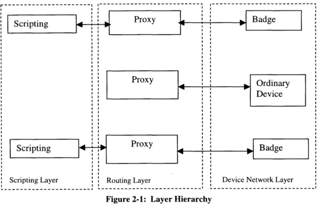
In essence we have defined the three layers of our layered automation environment - the device network layer, which forms the lowest layer of the system, the routing layer, which forms the intermediate layer of our system and the scripting layer, which forms the highest layer in the system. The scripting layer manages all scripts and provides an interface to the user, the device network layer manages the devices in the network and the intermediate layer provides the routing between these two layers. The scripting layer gets device commands and scripts from the user and it makes use of the routing layer to communicate these to the device network layer, which then carries them out. This architecture can be illustrated by Figure 2-1.
Our architecture has all the qualities of a layered system. The three layers are totally independent and have their own defined functionality. All three layers also have a well-defined interface, which allows them to communicate with each other. As in any layered system, our system would work even if any of our layers were to be replaced by another layer that has the same functionality and the same interface.
Portability is particularly important for our system. We could make dramatic changes to our system by simply replacing one of the layers. The device network layer implements a particular networking scheme for the devices. If at a later time we wish to change the scheme and move on to something different, we just have to replace the network layer with a new layer that implements the new scheme. For example, if we decide to have a wired network now, we can choose to go to a wireless network later on, or vice versa. Similarly, the routing layer implements a certain method of routing between the layers. If a different routing scheme is required we could
simply implement the scheme and introduce it in our system. The scripting could be similarly
would have to do is replace the scripting layer. As long as the interface between the layers is preserved, these changes may be done with ease.
2.1.1 Device Network Layer
The device network is the lowest layer of our architecture. It manages all the devices in the system as well as the communication between these devices and the rest of the system. The network consists of simple devices and gateways. The devices form the lower level in the hierarchy, with gateways being above them. The components of the network are explained below. More details can be found in [13].
2.1.1.1 Devices
Devices form the lowest level of our network hierarchy. A device could be something as simple as a light bulb to something more complex, like a television or a microwave. Each device in the system has some processing power in addition to its basic functionality. This is used to communicate with the gateway, which forms the next level in the network hierarchy.
Each device is always associated with a fixed list of possible controls (or commands) and responses (or status messages). Each control and response has a fixed list of possible values. For example, a speaker might have a 'volume' control and that might have values '1', '2', 'highest',
'lowest' and 'off'. The speaker might also generate a 'playing' response and it might have possible values 'music' or 'news', or 'off'. The device will only accept these controls and values and only generate these responses and values.
In our architecture, each user is represented by an entity called the badge. This badge is also a device in the device network and is handled as any other device in the network. This badge is referred to as the K21 device. The K stands for key. The K21 communicates with the system through a secure channel that encrypts all messages.
2.1.1.2 Gateways
Gateways form the next level in the hierarchy. They provide the interface between the devices and the routing layer. They convert messages coming in from the routing layer to a format that devices can understand and then route these messages to the appropriate device. They
also perform the reverse function, i.e., messages going from the device to the routing layer are also converted and routed.
2.1.1.3 Communication
Devices communicate with gateways using radio frequency (RF). The RF communication scheme in use is simple and reliable. RF is used to provide mobility to the devices. The gateway communicates with the routing layer using UDP/IP. The gateway hence converts between RF and UDP/IP.
Devices can receive commands that require certain actions to be carried out. A device will carry out these commands only if the sending device is allowed to control it. Commands from devices that do not have the right permissions are ignored. Devices can also generate responses whenever a significant change in their status takes place. These responses are only sent to devices that are monitoring the status of this device. The routing layer does this routing as and when required.
2.1.1.4 Location
The network allows devices to determine their location within the system. This is done using the Cricket location system [19]. It is important to note that Cricket does not allow the network to determine a device's location. It is up to the device to determine whether the system should know its location. This is useful for the K21 (user) device as it preserves each user's privacy.
2.1.1.5 Security
The device communicates with the routing layer through a secure channel that encrypts and authenticates all the messages. The HMAC-MD5 [10][20] algorithm is used for authentication and the RC5 [21] algorithm is used for encryption. Messages on this channel pass through the appropriate gateway, which converts them to the proper format. The user's K21 provides the necessary security.
2.1.2 Routing Layer
The routing layer is the middle layer of the architecture. It provides the necessary routing and interfacing between the scripting and the device network layers. This is done via a complex scheme that consists of the following components.
2.1.2.1 Name
Each device in the device network is given a 'name'. This name contains all the information relevant to that device, including
1. Actual name (e.g., Fred, Tom or LightBulb-1 etc.). When that device is created, this is the name its owner gives it.
2. Location (i.e., the room it is in). This is the information obtained from the device network using the Cricket system.
3. Service (i.e., what kind of device it is, e.g., microwave, light bulb etc.). 4. Allowed controls and their associated values.
5. Possible responses and their associated values.
6. The IP address and the port number used to communicate with the device.
This name is stored using a special format. This is the same format used by the intentional naming system (INS) [3]. The two main parts of the name are the attribute and the value. Together, an attribute and its associated value form an attribute-value pair or av-pair. A name is a tree of attribute value pairs. Levels of hierarchy are indicated by the use of square
([
and 1) brackets, and attributes and values are separated by the equals sign (=). An example device name for our system might be
[name=Tom
[location=Lounge] [ip=18.1.0.1[port=991]
[service=speaker
[control=volume[values=O, 1, 2, highest, lowest]] (control=play[values=true, false]]
[response=playing[values=true, false]]
[response=power[values=on, off]]
The name is actually represented as a string. Additional line breaks have been added in the example above to make it more readable. This example specifies a speaker device that has been named 'Tom' by its owner. It is presently located in the Lounge. To send messages to it, other devices should use the IP address 18.1.0.1 with port 99. The speaker has 3 controls
-volume, play and power. Each of these has associated values that it can take. Similarly, the speaker has two responses - playing and power. Each of these also has values it can take. In this example [name=Tom] is the top-level av-pair. Everything else is a child. [Location=Lounge], [service=speaker], and [ip=18.1.0.1] are siblings. [ip=18.1.0.1] also has a child - [port=99].
[service=speaker] has 5 children, each of which also has a child each.
An important feature of this naming scheme is that it supports wild-card matching of values. To achieve that, the value of an attribute is simply replaced by the wild-card token (*). For example, [name=* [ location=Lounge ] [ service=speaker] [ip=*]] refers to all speakers in the Lounge, irrespective of their name or IP address.
This naming scheme is very important to the system. Messages sent by devices include the origin and destination in their headers. Both of these are represented by this naming scheme. The routing layer routes the message using the destination 'name'. In case of the destination name having a wild-card value, the layer routes the message to all devices that match the rest of the av-pairs. Hence devices can send messages without fully specifying the destination.
2.1.2.2
Proxy
Each device in the system also has its own private proxy. The proxy can be thought of as a software version of the actual device. It is basically a piece of software that runs on a regular computer and its primary purpose is to provide access control for the device. The proxy communicates with the device through a secure channel that encrypts and authenticates all the messages. The HMAC-MD5 algorithm is used for authentication and the RC5 algorithm is used
for encryption. Messages on this channel pass through the appropriate gateway in the device network which converts the messages to the required format.
The proxy can implement computationally-expensive security algorithms and also keep large access control lists that enable it perform access control functions for the device. The proxy uses these mechanisms to act as a guardian for the device. The proxy authenticates users and only allows those with valid permissions to control the device.
As mentioned earlier, the K21 (user) device is just another device in the network and hence it also has its own private proxy.
2.1.2.3 Server Network
The servers are the next level in the routing hierarchy. Each proxy in the system is registered with a server. Together all these form a server network. All the routing done by this layer is carried out with the help of this server network, which also forms the most important component of this layer. The layer is thus also referred to as the 'Server Network'.
2.1.2.4 Communication
Whenever a device needs to send a message to another device in the network, it has to go through its own proxy. The device communicates with its proxy through a secure channel. The proxy provides functionality that lets the device send messages. The message is passed from the device to the proxy, which forwards it on to its server. The message contains the name of the destination device in the INS naming scheme. The server uses this information and the server network to determine the particulars of the destination device's proxy. The message is then sent to the proxy of the destination device. The proxy contains the intelligence to determine if the originating device should be allowed to communicate with its device. If so, the proxy forwards the message to the device through the normal secure channel.
Responses generated by a device do not include the destination in their headers. These responses should be sent to all devices interested in monitoring the status of that device. The device's proxy keeps a list of these 'listener' devices and sends the message to all of them. A device wishing to add itself to another device's 'listener' list will send the appropriate message to that device's proxy.
The proxy provides a few methods that can be used to send messages. These are
1. Indirect send - This is the standard send method. Devices usually use this method to send messages to other devices. The message is sent to the server network that determines the particulars of the destination device's proxy.
2. Direct send - This is the advanced send method. Devices use this when they know the particulars of the destination device's proxy and going through the server network is not necessary.
3. Query - This method returns a list of devices that match a specified pattern. The device could use this method to determine whether devices that match a certain pattern are available in the device network. For example, if the device wishes to send a certain message to the light bulb, it could use the query method to determine if the light bulb exists. The pattern being searched for is expressed in the INS naming scheme. The proxy determines this list of devices with the help of the server network. It searches the network for all devices that match the specified pattern and returns that list.
These methods form the interface to the routing layer. The routing layer enables the scripting and device network layers to communicate with each other through these methods provided by the proxy.
Messages received for a device by its proxy are forwarded on to its device. Sometimes the scripting layer is interested in listening to these messages to determine whether its scripts should be carried out. The proxy allows the scripting layer to add itself as a 'listener' of these messages. Whenever the device's proxy receives a message for the device, it is not only sent to the device but all the 'listeners' as well by the proxy.
2.1.3 Scripting Layer
The scripting layer is the top layer of our architecture. In simple terms it forms the front-end for the automation environment. It provides users with an interface to the system. This interface allows direct control of devices in the environment as well as the setting up of scripts for
how they should be automated. The layer manages these scripts and makes sure they are carried out as and when required.
The components of the scripting layer are explained below.
2.1.3.1 Distributed
The scripting layer only allows authorized users to control devices and set up scripts. As mentioned earlier, users are represented in the device network by K21 devices. An authorized user is someone who owns a K21 device. Each such user should have access to the scripting layer and should be able to control devices and set up scripts. An unauthorized user is not allowed access to the scripting layer.
One of the reasons for this requirement is security. Our system implements end-to-end security. Devices will only carry out commands from users that have permission to control them. In order to determine whether an incoming command is from an authorized user, the user's name is included in the command. The only tangible name that could represent the user in our system is the name of his K21 device. If the scripting layer was open for all to use, a malicious user could pretend to be someone else and potentially cause havoc.
The scripting layer is hence linked to the K21 and sits on top of the K21's proxy, thereby forming the top layer of our architecture. The scripting layer is distributed in the sense that each K21 has its own layer. It presents its user interface to the person represented by its K21. Each 'authorized' user thus has his own private interface to the system provided by his scripting layer. From that interface only he can send commands to devices and set up automation scripts for himself. Each user's scripting layer stores only that user's automation scripts and is responsible for managing and carrying out only those scripts. Ordinary devices do not have a scripting layer sitting on top of their proxy simply because they do not need an interface to the system.
Users do not share the scripting layer. Scripting layers of different users do not communicate with each other and have no knowledge of each other's scripts or operations. There is no way for these different scripting layers to share information. This preserves users' privacy. Additionally, whenever the user sends a command, or sets up a script, his name (i.e., his K21
name) is automatically included in the message by the scripting layer. This ensures that a user cannot pretend to be someone else. There is no way the user can modify this behavior.
In effect multiple scripting layers exist in our system. Each of these mini-scripting layers has to interface with at most one person, storing and managing only his scripts. All these mini layers can be thought to form one large scripting layer. Although the components of this layer do not interact, they perform the same basic operation.
Figure 2-1 shows the layer hierarchy of our architecture. It also illustrates how the mini scripting layers of different K21 s (users) combine to form one large scripting layer.
Scripting Proxy Badge
ProxyOrdinary
Device
Scripting Proxy Badge
Scripting Layer Routing Layer Device Network Layer
Figure 2-1: Layer Hierarchy
2.1.3.2 User Interface
The scripting layer provides the user with an interface to the automation environment. The interface is a graphical user interface. It allows the user to directly control any device in the
system and create automation scripts for these devices. It allows the user to do all this in a very natural and intuitive way. The interface is easy to use and the user is not required to go through a learning curve before successfully using it. This interface is provided to all 'authorized' users in the system.
2.1.3.3 Commands
Users are allowed to send commands to individual devices in the system directly. They are allowed to send commands to any device in the entire system. Only supported commands can be sent. Commands to multiple devices can also be sent.
Although a user is allowed to send commands to any device in the system this does not imply that the user has control over all devices in the system. All commands sent out automatically include the user's (actually his K21's) name in the header. When the routing layer, or more accurately the destination device's proxy receives the command, it decides whether the user is allowed to control the device. If so, the command is allowed.
2.1.3.4 Scripts
Users are allowed to create automation scripts involving any device in the system. These scripts can be broken down into 'triggers' and 'responses'. Each script waits for some condition, or trigger, on some device to be true before it can carry out some action, or response, on some other device. For example a script might be 'if X happens, do Y'. In this case X is the trigger and Y is the response. These scripts may even involve multiple triggers and multiple responses. These triggers and responses could also involve multiple devices.
Each scripting layer stores and manages its user's scripts in a proper format and makes sure that they are carried out as and when required. In order to do that the layer needs to monitor the network to see what messages get generated. Specifically it needs to monitor the status of each device involved in the triggers. It needs to add its K21's name to the list of status listeners for each such device. This is achieved by sending the appropriate message to each device. Whenever any of those devices changes state it will send out a response and the scripting layer's K21 will be one of the receivers of that message. To be able to react to these responses the scripting layer needs to receive these messages sent to the K21. It needs to register itself as a message listener for its K21. Sending an appropriate message to the proxy of its own K21 does this. After that all messages sent to that K21 are also sent to its scripting layer.
Whenever the scripting layer receives a response from one of the devices involved in the triggers, it checks to see if the device has attained the status required by the trigger(s). If so, the
trigger is considered 'fired'. When all the triggers for a particular script have happened, or fired, the script is considered enabled. At that time the responses are sent off. These responses are just like ordinary commands to devices. The scripting layer's K21's name is included in these commands by default. The destination device allows the command only if the K21 (i.e., user) has permission to control it.
As mentioned earlier, individual users have their own copies of the scripting layer. There is no way for the scripts of two different users to interfere with each other. Hence, a scripting layer only stores one person's scripts and does not worry about two users having conflicting scripts.
2.1.3.5 Communication
The scripting layer runs on top of the K2 1's proxy. The proxy forms the scripting layer's interface to the device network. The scripting layer uses its K2 I's proxy just like the K21 would. It has access to all the proxy methods that the K21 does. Whenever the scripting layer sends out a message using one of the proxy's methods, it adds its K21's name as the sender to the message header. This is done for all messages. So basically the scripting layer acts as the K21 whenever it needs to send out a message to the device network.
The scripting layer needs to send commands to the device network whenever the user wishes to control a device. This is done with the proxy's send method. The destination device name and the command are both obtained from the user. However before using the send, the scripting layer uses the proxy's query method to determine whether the device exists in the system. If so the command is sent.
For scripts the layer needs to use a few of the proxy's methods. Firstly it needs to register the K21 as a status listener for each device involved in the triggers of each new script. These messages are sent using the proxy's send method. These messages are sent and treated just like ordinary commands. The destination device name is obtained from the trigger.
The layer then needs to add itself as a message listener for its own K21. Calling another of the proxy's methods does this. The proxy adds the scripting layer as one of its listeners and from that point on, forwards all received messages to it.
The layer also needs to send out the responses when necessary. Before that is done, the layer uses the proxy's query method to determine whether the device involved in the response exists in the system. If so, it sends out the response message to that device using the send method. Lastly the layer also needs the ability to determine the K21's (user's) location. Some automation scripts could involve conditions based on the user's presence in a certain room and the user's location is hence important. This information is obtained from the device network layer. The scripting layer communicates with the K21 directly to determine its location. The device network allows the K21 to determine its own location, as mentioned earlier. The K21 passes this location on to the scripting layer. This is the only instance of the scripting and device network layers bypassing the routing layer to communicate with each other.
2.2
Communication between Layers
Our automation environment is an event-driven system. Messages from one device to another are made up of events. Each device will generate an event when it needs to convey some information to the rest of the system. Commands, responses and queries are all sent out as events. The proxy methods mentioned earlier accept events as their arguments. Each event contains enough information to determine the sender, the receiver and also the message to be sent. The sender and receiver are always expressed in the INS naming scheme. The significance of using events is that polling can be avoided. In a distributed system polling can cause a lot of difficult problems.
The layer interface is defined by these events. To be compatible with the layer interface, the scripting layer is able to receive and send events and also convert to and from the event format. Following are the important events that are used by the scripting layer.
* CommandEvent - Directed to a device, asking for an action to take place. The required action is included in the event. This event is used as an argument for either of the proxy's send methods. The scripting layer uses this when the user wishes to directly control a device and when sending out script responses. The action to be taken is expressed in the
destination device's allowed controls. The value is one of the allowable values for that control. For example, an action for a speaker might be [volume=highest ] .
" AudioEvent - Sent by devices that generate audio. These contain audio data expressed in raw bytes. These events can be sent to speaker devices or directly to a user (i.e., his K21). The user can choose how to listen to the audio message contained in the event. This is sent using the proxy's direct send method as it needs to be transmitted fast.
" QueryEvent - Requests a list of names that match a specified pattern. The pattern is included in the event and is expressed in the INS naming scheme. This event is used as an argument for the proxy's query method. The pattern will almost always include a wild-card token.
* ResponseEvent - Returned by the proxy's query method. Contains a list of devices that matched the specified pattern.
* AddListenerEvent - Sent out by the scripting layer when it wishes to listen to StatusChangeEvents from a particular device. This is sent to the device that is to be monitored like a regular CommandEvent. The proxy of the destination device will add the scripting layer (actually the K21) as a 'listener' for its device only if the K21 is allowed to monitor that device's status. Each device's proxy keeps a list of all such listeners.
* StatusChangeEvent - Sent by a device, indicating that something significant has
happened to it. This event is sent using the proxy's send method. This event does not have a destination field. The proxy forwards it to everyone in its list of listener devices. The status message is expressed in the INS naming scheme with one av-pair. The attribute for that av-pair is one of the device's possible responses. The value is one of the allowable values for that response. For example [playing=true] might be something a speaker sends back, indicating that it is playing some sound.
3 Implementation
This section presents the implementation details of the scripting layer. The implementation details of the device network layer can be found in [13]. The details of the routing layer are in the progress of being documented and can be found in [4].
We have implemented a scripting layer that provides users with an interface to the system, allowing them to control devices and set up automation scripts. The layer stores all such scripts and with the help of the routing and device network layers, ensures that they are carried out. All code for the scripting layer has been implemented using the Java programming language. The layer basically performs three very special duties. One is providing the user with an interface to the system, another is script management and the third is interfacing to the routing and device network layers. Each of these three duties is independent and very specialized. Therefore, the scripting layer can be thought to comprise of three very distinct entities, each one performing one of the special duties of the scripting layer. These are the User Interface, Scripting and the Device Interface. The User Interface, as the name suggests, provides the necessary interface to the user. The Scripting holds all automation scripts created by the user and is in charge of managing and carrying out these scripts. Both these entities frequently need to communicate with the K21 device as well as the other devices in the device network. The Device Interface handles this communication.
The Scripting entity can actually be broken down into several smaller entities, each one representing a single automation script. For each new automation script created by the user, one of these 'Script' entities is instantiated with the necessary triggers and responses. Each of these 'Script' entities will store and manage only that script. These entities cannot communicate with one another and have no knowledge of other scripts. A Script object will wait for its triggers to be generated before sending out the appropriate responses to the proxy. This scheme allows all the different scripts created by the user to be run simultaneously and in parallel to each other. Each script fires off its responses whenever the conditions are right, irrespective of any other script. All scripts have the same priority level. Any one message coming in from the routing layer could
trigger off more than one automation script. All such scripts send off their responses simultaneously. There is no upper limit on the number of scripts allowed for a user.
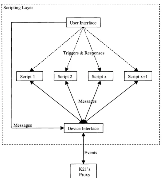
Figure 3-1 illustrates the architecture of the scripting layer.
r---I
Scripting Layer
User Interface
Triggers & Resi~onses
Script I Script 2 Script x Script x+1
Messa es Messagesrn Device Interface Events K21's Proxy
Figure 3-1: Architecture of Scripting Layer
3.1 Initialization
When a new user wishes to enter the system he is assigned a K21. Whenever that K21 is brought online in the device network, a new scripting layer is created for that K21, along with a
proxy. The new scripting layer is owned by the K21 and it provides the K21's owner (i.e., the
This process is repeated for all new K21 devices. All ordinary devices only get a proxy when they are brought online.
3.2 User Interface
The User Interface enables the user to send commands to devices and to set up automation scripts. Commands are passed directly to the Device Interface, which converts them to events and sends them to the K2 I's proxy. If the user wants to create a script, an instance of the Script class is instantiated with the necessary triggers and responses.
The user interface is the front-end of the system. It is a highly critical portion of the system as it has a direct effect on the system's usability. Therefore, it is very essential for it to be easy to use and intuitive. People should want to use the system and not have to go through a learning curve before they can start. The scripts required by the user might, in some cases, be very complex. The interface should allow the user to set up these complex scripts with minimal effort. Special consideration has been given to choosing the interface that best suits the needs of the system.
3.2.1 Choosing the right interface
In order to devise the most useful interface for the system we considered a number of possible interface options. Below is a list of these.
3.2.1.1 Speech Interface
Speech is probably the most natural of all interfaces. It is natural for humans to speak and to expect a response. Enabling a user to use his voice to specify scripts or to issue commands will make the system very user-friendly and usable. Such a system will have a small learning curve and it will be highly intuitive.
Speech, however, also has its problems. For one, it is too difficult to specify a complex script using just voice. One can imagine a script containing multiple triggers and multiple responses. Such a script will probably be very long and dictating it can be difficult and error prone. A user could unknowingly mix up triggers and responses or leave out a condition. To get it right he would have to extremely careful and formal.
If there are multiple people in the same room, communicating with the system using
speech can become very confusing. If more than one user wishes to communicate with the system at the same time, it will be very difficult to understand all the different voices. The scripting layer will need to do voice filtering to filter out all the different voices. It will also need to do very exact voice recognition to determine the voice of its user. It will also be distracting for the users themselves. Additionally, these communications with the scripting layer might be private which will restrict the user to carrying them out only when he is alone.
Lastly, no perfect speech recognition engine exists. Most speech recognition engines perform well, but not perfectly. We looked at a couple of speech recognition engines, which are described below.
3.2.1.1.1 SLS-Lite
SLS-Lite [16] is a utility for easily building and running spoken language systems. The utility has a web-based interface through which it allows developers to create their own
personalized spoken language system. SLS-Lite then allows these applications to be run with the help of the GALAXY [18] system, which was developed at the Spoken Language Systems Laboratory (SLS) at MIT [24].
To create a spoken language system, a developer first has to specify a domain. A domain can be thought of as a context for the application. For example, if the user wishes to have a spoken language system that will allow him to control devices in his house the domain could be his house. Creation of a domain involves setting this context along with possible phrases that the user might wish to use when referring to this domain. For example, if the domain is the house, one of the phrases could be 'switch the lights on'. The developer will need to specify as many of these phrases as possible.
SLS-Lite adds the user's domain(s) to GALAXY's global list of domains. The developer's application can then send received audio directly to GALAXY. GALAXY uses the information in its global domains to determine whether the incoming audio is an allowed phrase.
If it can successfully match the audio, it returns an attribute-value pair to the developer's
example, if the audio received by the system is 'turn off lights', the attribute-value pair returned could be 'lights=off'.
This system performs very good speech recognition. It matches the incoming audio to its domain very well and returns mostly correct data. Other systems have been built at SLS that make use of the GALAXY system and demonstrate its power and usability. These include
JUPITER [26], and Mercury [23]. JUPITER provides weather information over the telephone.
Anyone can dial in and ask the system for the weather forecast of any city in the world. Mercury is a flight reservation system. It too works via a phone interface. People can dial in to plan and price itineraries between major airports worldwide. Both systems perform very well and allow users a certain degree of latitude in the questions they can ask. Another good feature of GALAXY is that it does not need to be trained before it can recognize speech from a new user.
The downside of GALAXY is the concept of the domain. In order to use it effectively for our system we would have to create a domain that would include each and every device that might exist in the device network, along with each and every phrase that might be used to control those devices. Any additions to the device network would need to be incorporated in the domain. That is a very difficult task and it lacks the flexibility that is required by our system. Having to re-define the domain for each device in the system will certainly become very tedious and time consuming. In addition we would need to make our system understand the attribute-pair received from the GALAXY system.
Another problem with GALAXY is that it does not differentiate between the voices of different users. So with multiple users speaking at the same time, it could get confused and produce false data.
3.2.1.1.2 IBM ViaVoice
IBM's ViaVoice software [7] uses the traditional approach to speech recognition. It requires extensive training of the system by the user before it can begin to recognize his voice. The user has to read a preset list of documents to the system. The process takes a long time if done properly.
The advantage of using ViaVoice is that it can be seamlessly integrated into our existing Java code. The IBM ViaVoice Software Developer Kit for Java [8] is a Java programming interface for speech that gives Java application developers access to the IBM ViaVoice speech technology. The SDK supports voice command recognition, dictation, and text-to-speech synthesis, based on the IBM ViaVoice technology. The SDK is an implementation of most of the Version 1.0 of the Java Speech API [9].
However, we tried the system and the results were not too impressive. Even after hours of training, the performance was far from perfect. Additionally it required the speaker to have a near perfect American accent. Words spoken with different accents were usually ignored by the system. Interestingly, sometimes the system understood a stranger (i.e., someone who had not trained the system).
If we were to use ViaVoice, each new user entering our system would need to go through
hours of voice training before he could use the system effectively. That is simply unacceptable in our scenario. Even with the training the performance is much worse than our requirements.
3.2.1.2 Keyboard/Typing Interface
Using a keyboard to interface with the system is another possibility. It would make perfect sense to use a keyboard along with a scripting language, like Perl [17], to define scripts. People who are familiar with Perl can use it to create complex and extremely useful scripts in a matter of minutes. Perl is a very useful language and using a Perl-like scripting language would enable people to create very powerful scripts for the system.
This would be useful for Perl experts, but people who have no knowledge of Perl would not be able to use the system with a lot of effect. They would have to go through the learning curve for Perl (or our scripting language) before being able to use the system. That is not acceptable. Additionally, a keyboard is not user-friendly at all, except for professional typists. Typing is difficult and laborious, especially if one has to type long scripts with lots of triggers and responses. Hence, the keyboard interface is also not acceptable for our system.
3.2.1.3 Graphical User Interface (GUI)
A graphical user interface (GUI) solves the problems presented by the keyboard
interface. It is very natural to use and highly intuitive. A GUI like the one Microsoft Windows [12] uses is very easy to understand and use, even for new users. Users do not need to type, and hence don't need to learn which keys lie where on the keyboard. They just need to learn to point and click. Even though it is not as natural as the 'ideal' speech interface, it is still the best available choice as far as user friendliness is concerned.
The additional benefit is the ease of specifying scripts, even with multiple triggers and responses. With appropriate drop-down menus and lists with scroll bars, users can specify a wide variety of conditions with extreme ease. Additionally, to send a direct command to a device, the user could select the device from a list of devices, select the command and send it. This interface has a lot of advantages over the other two interfaces and therefore, the interface provided by the
scripting layer is a graphical user interface.
3.2.2 Details of the GUI
The interface was implemented in the Java programming language, as was the rest of the layer. A visual development tool like J++ Builder was not used to implement the graphic interface. This made the development much more difficult than it could have been, but it allowed greater flexibility in the design of the interface. Our interface is much like the standard GUI provided by a Microsoft Windows application. It consists of standard GUI components, like windows, tabbed panes, drop-down lists and buttons.
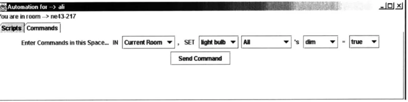
3.2.2.1 Commands
The interface consists of one window with lots of options. The window has a tabbed-pane, with one pane representing commands and the other scripts. Figure 3-2 shows the user interface for a user whose K21 device is named [name=ali [ service=K21 .
r2!Automation for --> all .X
You are in room --> NE43-217
(SCW Commands
Enter Commands in this Space... IN Room , SET Device w DeviceName w s Control w = Value
Send Command
Figure 3-2: The Command Pane
The window displays the command pane as 'Commands' is selected from the tabbed pane. The title of the window is 'Automation for - ali'. The user interface picks out the actual name from the INS name of the K21. Below the title the window displays the current location of the K21 (i.e., user). As the user changes his location his user interface keeps updating his current location. This is useful in creating scripts and commands as the user does not need to remember the name of his current room.
The 'Room' drop-down list displays all the rooms in the system. This list is updated frequently as new rooms could potentially be added to the system at any time. The names 'Global', and 'Current Room' are added to the list of rooms. 'Global' signifies all rooms in the system and 'Current Room' signifies the user's current location.
Once a room is selected, the 'Device' drop-down list will display all the different device
types in that room. A device type could be a light bulb or a speaker. If a K21 device is present in the room, 'User' is added to the list of device types. If 'Global' was selected, all device types in the system are displayed. If 'Current Room' was selected, all device types in the user's current location are displayed.
Once a device type is selected, the 'Device Name' drop-down list will display the names of all devices of that type in the required location. Among this list are 'All' and 'Any'. If the user wishes to control a specific device, he should select the name of that device in the Device Name list. If he wants to send the command to any device of that type, he should select 'Any'. However, if he wants to send the command to all devices, he should choose 'All'.
Once the name is selected, the 'Control' list will display all the possible controls that device allows. As mentioned in Section 2.1.1.1, each device is associated with a fixed list of
control. The user should select the option he wishes to control. That brings up a list of possible values for that control in the 'Values' list. For example, a speaker's 'volume' control might have values that are '1', '2', 'highest', 'lowest' and 'off'. The user should select the appropriate value and click the 'Send' button.
Upon clicking the Send button, the User Interface reads the selected items from each drop-down list. These items specify which device the user wishes to control and exactly how he wishes to control it. This information is passed on to the Device Interface, which converts it to an event before sending it to the routing layer.
The command pane allows the user to send commands in a very versatile manner. The user can choose to control a single device or multiple devices. The user can choose the device exactly, specifying its location, type and name, or he can control a device without specifying its exact details. For example, the user can control all the light bulbs in a room, or a single light bulb in a room. More examples are provided in Appendix A - Command Examples.
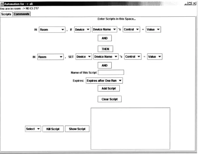
3.2.2.2 Scripts
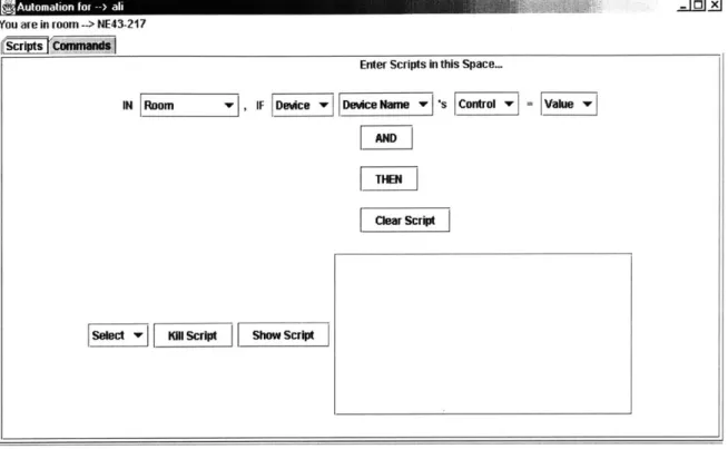
.=Jz131
You are in room --> NE43-217
Enter Scripts in this Space.
IN Room vlIFDevce Device NamewsControl =Vahue u AND
[TEN
Clear Script
Select
ll
So scrIpt Show ScriptFigure 3-3: The Initial Script Pane
To create scripts, the user needs to specify triggers and responses. Figure 3-3 contains an empty trigger. The empty trigger looks just like a command option. However, the command option's 'SET' is replaced by an 'IF' indicating that this is a condition. Just like the command option, the user has to select a room, a device type within that room, then a device name. Once that is done, the 'Control' drop-down list will contain all the possible responses the selected device can generate. For example, a speaker might generate a 'playing' response.
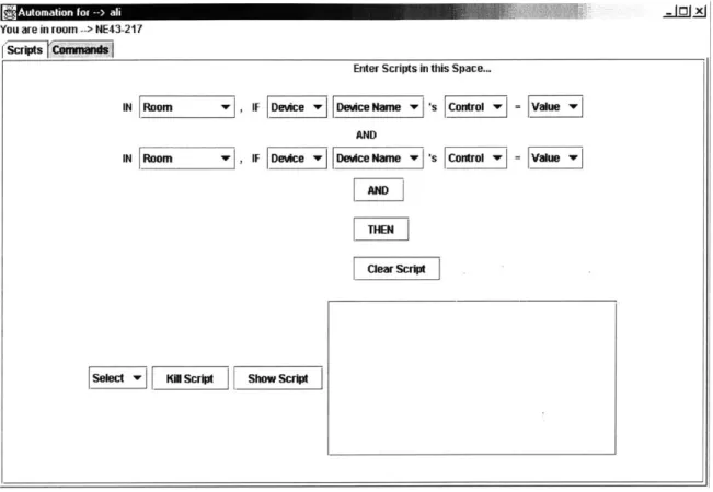
Upon selecting the response, the 'Value' drop-down list will contain all the possible values for that response. The speaker's 'playing' response might have possible values of 'music' or 'news'. With the user's selection of the required value, the trigger is completely specified. This trigger will be considered 'fired', or enabled if the selected device sends out the selected response with the selected value.
A special case is when the selected device is the user's K21. In that case, the Controls list
will include the options 'Enters', 'Leaves' and 'Receives'. For 'Enters' and 'Leaves', the corresponding Values list will include a list of all rooms in the system. This list will include the value 'Any Room'. These options enable the user to create a script with his entering or leaving a