READ THESE TERMS AND CONDITIONS CAREFULLY BEFORE USING THIS WEBSITE. https://nrc-publications.canada.ca/eng/copyright
Vous avez des questions? Nous pouvons vous aider. Pour communiquer directement avec un auteur, consultez la
première page de la revue dans laquelle son article a été publié afin de trouver ses coordonnées. Si vous n’arrivez pas à les repérer, communiquez avec nous à [email protected].
Questions? Contact the NRC Publications Archive team at
[email protected]. If you wish to email the authors directly, please see the first page of the publication for their contact information.
NRC Publications Archive
Archives des publications du CNRC
This publication could be one of several versions: author’s original, accepted manuscript or the publisher’s version. / La version de cette publication peut être l’une des suivantes : la version prépublication de l’auteur, la version acceptée du manuscrit ou la version de l’éditeur.
Access and use of this website and the material on it are subject to the Terms and Conditions set forth at Innovative wing tip equipped with morphing upper surface and morphing aileron for greener aviation
Botez, Ruxandra Mihaela; Koreanschi, Andreea; Gabor, Oliviu Sugar; Mebarki, Youssef; Mamou, Mahmoud; Tondji, Yvan; Brianchon, Guillaume; Tchatchueng, Joel; Guezguez, Mohamed; Salinas, Manuel Flores; Grigorie, Lucian; Carranza, Oscar; Amoroso, Francesco; Pecora, Rosario; Lecce, Leonardo; Amendola, Gianluca; Dimino, Ignazio; Concilio, Antonio
https://publications-cnrc.canada.ca/fra/droits
L’accès à ce site Web et l’utilisation de son contenu sont assujettis aux conditions présentées dans le site LISEZ CES CONDITIONS ATTENTIVEMENT AVANT D’UTILISER CE SITE WEB.
NRC Publications Record / Notice d'Archives des publications de CNRC: https://nrc-publications.canada.ca/eng/view/object/?id=9fd93f90-1a5d-4ad6-835a-52b48da0af4d https://publications-cnrc.canada.ca/fra/voir/objet/?id=9fd93f90-1a5d-4ad6-835a-52b48da0af4d
Innovative Wing Tip Equipped with Morphing Upper Surface and Morphing Aileron for Greener Aviation
Ruxandra Mihaela Botez, Andreea Koreanschi, Oliviu Sugar Gabor
Research Laboratory in Active Control, Avionics and AeroServoElasticity LARCASE Ecole de technologie supérieure, Montreal, Que., Canada
Youssef Mebarki, Mahmoud Mamou
The Institute of Aerospace Research - National Research Council of Canada IAR-NRC Ottawa, Canada
Yvan Tondji, Guillaume Brianchon, Joel Tchatchueng, Mohamed Guezguez, Manuel Flores Salinas, Lucian Grigorie, Oscar Carranza
Research Laboratory in Active Control, Avionics and AeroServoElasticity LARCASE Ecole de Technologie Superieure, Montreal, Que., Canada
Francesco Amoroso, Rosario Pecora, Leonardo Lecce
University of Naples “Federico II”,
Industrial Engineering Dept. - Aerospace Division, Naples, Italy
Gianluca Amendola, Ignazio Dimino, Antonio Concilio
The Italian Aerospace Research Center CIRA Adaptive Structure Division, Capua (CE), Italy
Abstract
A wing tip demonstrator equipped with a conventional aileron and with a morphing aileron was designed, manufactured and tested during three wind tunnel sessions at the NRC subsonic wind tunnel facilities in Ottawa. Experimental data during wind tunnel tests was recorded from 32 Kulite sensors installed on the morphing skin, Infrared readings and Loads balance. During the 1st and 2nd set of tests, the morphing wing equipped with its rigid aileron was studied. During the 3rd set of tests, the morphing wing was equipped with the morphing aileron. The morphing aileron and the transition flow optimization results, for the 3rd set of tests, are discussed in this paper. Despite the many challenges, the experimental results have shown that delays of the flow transition of up to 8% of the chord were achieved.
1. Introduction
In a world in a continuous change, the aerospace research has to achieve innovative designs in order to reduce their costs, and the impact of the aerospace industry on the environment. With this objective in mind, national and international collaborations were developed between academic partners, such as universities and research centers, and the industrial partners. Some of the most known, and with the greatest impact are the Clean Sky project in Europe, and the Green Aviation Research and Development Network (GARDN) in Canada, many other collaborations can be found in the United States of America or Japan.
Researchers compete to find the best solutions to be applied, both on long and short terms, and one such solution was the ‘morphing of the aircraft’. Aircraft morphing was not a new concept, as it was applied by the military aviation on some their more well-known aircrafts, such as the Grumann F-141, the North American Aviation XB-70 Valkyrie prototype2 and the AFTI/F-111 'Mission Adaptive Wing'3. Recently, the concept of morphing started being researched for the civil and unmanned aviation as well.
For the unmanned aerial vehicles, research was conducted by many teams. Some of the most interesting morphing applications were described by Sofla et al4 and Barbarino et al5 in their literature review papers. Interesting research on the effect of morphing of the UAS wing on its aerodynamic performances was conducted by Sugar et al6 and 7.
A project that was dedicated to developing a new concept of morphing wing for civil aviation was the CRIAQ 7.1 project8. This project was developed as collaboration between Bombardier Aerospace, Thales Canada, Ecole de Technologie Superieure, Ecole Polytechnique and the Canadian National Research Council (CNRC), in Canada. The purpose of the project was the development of a wing model able to change its upper surface using controlled motion of two lines of shape memory alloy actuators installed on the wing upper surface skin9 and 10. The morphing upper surface skin itself was developed through optimization techniques using Carbon-Kevlar composite. The model’s capabilities were tested at the CNRC subsonic wind tunnel in Ottawa, and the wing model was tested for the objective of flow transition delay. The results have shown that the wing model achieved high transition delays and that the balance measurements have given drag coefficient reductions of up to 20%11. A subsequent aeroelastic
study proved that the morphing technique would not induce flutter phenomena during wind tunnel testing12. In addition, many breakthroughs were achieved in active open-loop13 and closed-loop14 control using PID15, fuzzy logic and neural network controllers in wind tunnel testing16-17 under the auspices of this project.
More recently, European community funded many research program involved to improve the morphing structures technology readiness level. SARISTU18 (acronym of Smart Intelligent Aircraft Structures) was probably the most advanced large-scale integrating project on morphing structures, coordinated by Airbus, aiming at achieving reductions in aircraft weight and operational costs, as well as an improvement in the flight profile specifically related to aerodynamic performance. Ended in 2015, the project released a joint integration of different conformal morphing concepts in a laminar wing with the aim to improve aircraft performance through a 6% drag reduction inside the lift coefficient range usually devoted to cruise, with a positive effect on fuel consumption. The project delivered the first full-scale completely morphing wing tip prototype, ever assembled in Europe, at Finmeccanica Headquarters (Pomigliano, Italy). The innovative seamless morphing wing incorporated a gapless morphing leading edge, a morphing trailing edge and an adaptive winglet.
2. Project presentation
The research presented in this paper was conducted in the frame of the CRIAQ MDO 505 project ‘Morphing Architectures and Related Technologies for Wing Efficiency Improvement‘. This project was an international collaboration between Canadian and Italian industry, academic and research teams. The Canadian partners were Bombardier Aerospace, Thales Canada, Ecole de Technologie Superieure (ETS), Canadian National Research Council (CNRC) and Ecole Politechnique. The Italian partners were Leonardo Finmeccanica, the University of Naples Federico II (UNINA) and the Italian Center for Research in Aerospace (CIRA). The purpose of the project was to develop a full-size wing tip structure equipped with a morphing upper surface and two types of ailerons: an innovative morphing aileron and a conventional rigid aileron. The objective of the development of such a wing-tip was threefold: 1)through upper surface morphing and aileron morphing change the shape of the wing and influence its aerodynamic performances towards delay of the transition of the flow between laminar and turbulent states19; 2)through optimization of the structure and of the upper surface composite skin, maintain a wing
structure that respects structural requirements for certification and remains similar to a real aircraft wing tip structure20 and 21; and 3)demonstrate that an integrated control system for the morphing upper surface and ailerons can achieve the desired shapes obtained during optimization22 and 23.
The research presented in this paper concerns the transition optimization results from the wind tunnel tests where the wing tip demonstrator was equipped with both morphing upper surface and morphing aileron.
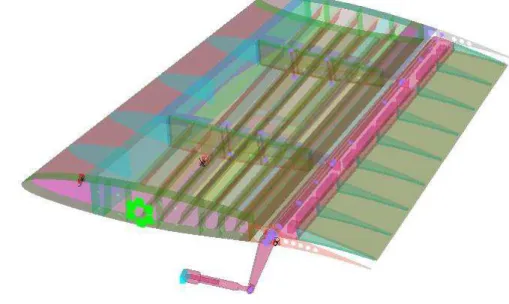
3. Wing Tip Demonstrator a. Wing Tip Structure
The wing tip structure was based on a real industrial aircraft wing tip without winglet, for which the aileron extends the full span length of the wing. The wing had a 1.5 m root chord and 1.5 m span, with a taper ratio of 0.7. Its internal structure respects the general layout for an aircraft wing structure, with two spars situated at 20% and 65% of the chord and four ribs, two of them being situated in center of the wing. The positions of the spars gave the limits of the morphing upper surface skin. The morphing upper surface skin was designed to respect the requirements that an aluminium skin respects, and to have a structural role as well as a morphing one. The material from which the morphing skin was manufactured was a carbon composite material designed and optimized specifically for this project. The deformation of the skin was obtained through the controlled displacements of four electrical actuators. The actuators were installed in pairs on each of the central ribs. The displacements of the actuators were grouped in a database developed from the optimization process where each set of displacements corresponds to a flight case (speed, angle of attack and aileron deflection). The control of the actuators was realised with four various controllers – PID, Fuzzy Logic and two Neural Network methods – and was validated using the measurement systems. The wing was equipped with 32 kulite pressure sensors installed in two parallel staggered lines at 60 cm from the root of the wing.
Three accelerometers were installed on the wing: on the wing box, on the aileron and on the balance shaft, in order to observe, for safety purposes, the vibration behaviour of the wing tip during wind tunnel tests.
The wing tip was manufactured at NRC and at ETS, and respected the technological requirements required by the industry.
Figure 1 Wing Tip demonstrator general structure layout
b. Morphing Aileron
An important component of the wing tip, with high impact on its aerodynamic performances, is the aileron. The conventional aileron, found on most aircraft wings, has a disadvantage that emboldened the research for a concept to replace it. The disadvantage of the conventional aileron lies in the manner in which it changes the camber of the wing. The aileron rotates around its hinge point and it creates a discontinuity in the slope of the airfoil camber line. For high deflection angles, this discontinuity can lead to a premature boundary layer separation and to a loss of efficiency for the aileron.
Therefore, the concept of a morphing aileron has been developed to replace the conventional rigid aileron and thus avoid the problem of the discontinuity. In their paper, Pecora and Barbarino24 have demonstrated the applicability of shape changing high lift devices applied on a
regional aircraft. They have successfully demonstrated the capabilities of a high lift device prototype. Also, Barbarino and Pecora25 and Ameduri and Brindisi26, have shown the possibilities of using the SMA materials when developing shape changing devices. They developed an airfoil morphing model equipped with a morphing flap device using SMA actuators. A more conventional actuation system suitable for morphing devices was proposed by Dimino et al27. Its peculiarity consisted of an un-shafted distributed servo-electromechanical arrangement deployed to achieve the shape transition from the baseline configuration to a set of design target shapes in operative conditions. Additionally, it was self-contained within the structure assuring a smooth surfaces exposed to the flow without fairing. G. Diodati et al28 analysed the performances of an adaptive trailing edge for a medium-size aircraft towards fuel consumption reduction.
Although the aileron region is a very delicate zone, where aeroelastic phenomena may be very important due to the very reduced local structural stiffness and the complex aerodynamic, the morphing aileron is aimed at enhancing aircraft efficiency during flight by compensating aircraft weight reduction due to fuel consumption. During classical manoeuvers, this conformal and no-gap device remains locked and the aileron works in the usual manner29. When activated, the morphing function is added to the conventional control surface, which remains free to rotate around its main hinge axis, thus preserving the prevalent purpose of the system. However, due to much-reduced space, the assembly and integration of actuator and kinematics into the morphing structure remains one of the most important design challenges.
The proposed architecture (Figure 2) was designed according to transport regional aircraft specifications. The morphing aileron consists of: (i) five segmented rib connected by means of rotational hinges positioned on the camber line creating a kinematic chain assuring enough structural robustness and transmitting deformation; (ii) spanwise stiffening elements such as spars and stringers in a multi-box arrangements; (iii) three servo-rotary actuators which drive the mechanism; (iv) a segmented skin (“armadillo-like” configuration) with silicon gap fillers to avoid discontinuities between adjacent parts and to ensure low friction sliding during morphing.
Figure 2 Sketch of the morphing aileron trailing edge29
4. Aerodynamic Optimization a. Genetic Algorithm
During the wind tunnel tests, both the wing upper surface and the aileron shapes were modified based on the numerical optimization results. For the wing upper surface morphing, the optimization has provided a set of four actuators displacements for each flight case, where a flight case refers to a combination of speed, angle of attack and aileron deflection angle. For the aileron morphing, the optimization has provided a shape for each desired deflection, while respecting constraints related to the constant thickness of the aileron, to maintaining a constant slope when aileron was morphing and the established convention for measuring the aileron deflection angle.
It was assumed that the central region of the wing, between the two center ribs on which the actuators were installed, would have a planar shape, thus the flow in this area would have bi-dimensional characteristics. Therefore, the optimization was conducted on the wing’s airfoil.
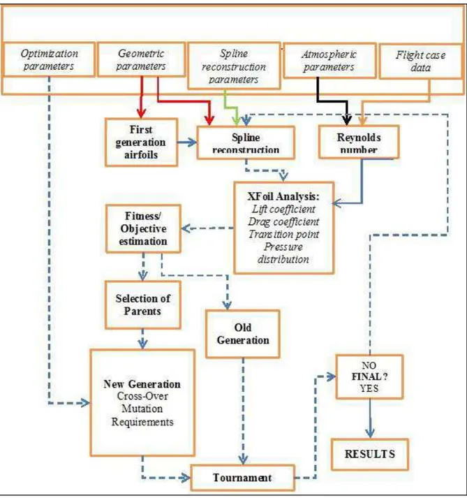
All the optimization, for both morphing upper surface and morphing aileron was performed with an ‘in-house’ developed genetic algorithm optimizer. The genetic algorithm optimizer was coupled with a cubic spline routine for the upper surface airfoil reconstruction, and with the
XFoil aerodynamic solver for fast analysis of the optimized shapes. Figure 3 presents the schematics of the optimization software.
Figure 3 Genetic algorithm optimizer coupled with cubic spline and Xfoil
The genetic algorithm optimizer used a tournament process, and a two-step cross-over function to speed up its convergence. The optimal mutation parameters: the probability of mutation and the amplitude of mutation were defined based on percentages of the population and on the allowed maximum displacements. The optimizer was set to end the process after an
established number of generations had passed. The fitness function was based on multiple objective functions developed from the aerodynamic parameters that were calculated with the XFoil code. The results of the optimization were actuator displacements for the wing upper surface skin and morphed shapes for the morphing aileron.
The optimization algorithm was compared with two other optimizers, the artificial bee colony and the gradient method. Its results were validated with experimental results from the CRIAQ MDO 505 wind tunnel test sessions, and from other morphing wing projects30-32.
b. Upper surface optimization
In order to achieve the upper surface optimization objective, the improvement of the boundary layer behaviour was performed through the delay of the flow transition from its laminar to turbulent state. In order to achieve this objective the upper surface skin of the wing was replaced with a carbon composite flexible skin located between 20% and 65% of the chord, along the wing span. Two pairs of actuators were installed on the central ribs at approximately 60 cm and 117 cm from the wing’s root. On each rib, the two actuators were installed at 32% and 48% of the chord. The positions of the actuators were considered control points during optimization, and were used as spline points for the cubic spline reconstruction of the wing’s morphing upper surface in order to continue with the aerodynamic analysis.
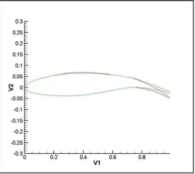
During optimization, the length of the skin was allowed to change with maximum 0.3% of its original length and the actuators were allowed to move with a maximum of 3.5 mm. The actuators were allowed to move vertically in both directions, giving a total displacement of 7 mm. The vertical distance between two actuators situated on the same rib was limited to less than 6 mm in order to avoid having high forces acting on the composite skin, and impacting in a negative way the desired shape for the wing. Figure 4 presents the application of the concept for an airfoil.
The objective function was based on the drag coefficient and transition values calculated by XFoil:
1 2
( morphed unmorphed) ( Dmorphed Dunmorphed) f unmorphed Dunmorphed Tr Tr C C F w w Tr C (1.1)
Where Ff represents the fitness function, Tr represents the transition point and CD is the drag coefficient, as calculated by Xfoil for the original shape of the airfoil and for each of the morphed versions.
The application of the optimization methodologies on the CRIAQ MDO 505 wing airfoil was presented in detail by Koreaschi et al33.
Figure 4 Example of the optimization and positions of the control points
c. Aileron optimization
The optimization of the aileron shape was performed using the same genetic algorithm optimizer that was developed for the upper surface skin morphing concept. The algorithm was applied to a series of nodes along the camber line. Each node moved according to the constraints and the desired deflections, and the displacement of each node conducted to the displacement of the next node until the whole aileron shape was deformed.
For the conventional aileron, the main problem resided in the rotation of the entire control surface around its hinge point, which created a discontinuity of the slope of the airfoil camber line. This discontinuity was also reflected over the upper and lower surfaces. At high deflection angles, this discontinuity can lead to premature boundary layer separation, and a loss of efficiency of the control surface.
Consistence between the conventional and the morphed aileron deflection angles was another constraint that was taken into account. The overall aileron deflection angle, calculated as the
angle between the horizontal (which is defined as the position of the aileron at zero degree deflection) and the tip of the trailing edge of the morphed aileron shape, must remain consistent with the overall deflection angle of a conventional aileron.
Another constraint was related to the camber line of the aileron. The curvature of the camber line must maintain a constant slope from the articulation point to the tip of the aileron.
The aileron camber line has been divided into several chord-wise sections, each defined by a starting and an ending point. The starting point of the first section coincided with the original hinge point, while the ending point of the last section coincided with the tip of the trailing edge. For each point along the camber line, two corresponding points on the upper and lower surfaces of the wing were defined based on the local thickness of the airfoil section. In addition, for each section, the coordinates of the hinge point were calculated, so that the rotation of any section with respect to the previous section preserved the continuity of the camber line.
Using this method, the deflection of any chord-wise section, with respect to the section directly upstream of it, preserved both the local thickness of the airfoil and the length of the segment, since rotation has not modified any other geometrical characteristics. If all aileron segments were rotated in the same direction, than the overall deflection angle of the aileron, as measured at the trailing edge and using the original hinge point as reference, was simply the sum of all segment rotations, each segment being rotated with reference to the segment immediately upstream of it.
By controlling the number of chord-wise segments, as well as the local rotation angles for each individual segment, a high flexibility in the shape changing of the aileron could be obtained, see Figure 5. All these degrees of freedom could be adjusted to match the technological limitations associated to the fabrication process of such an aileron.
Comparisons of aerodynamic performances, given by numerical analysis, between the conventional and morphing aileron were presented by Koreanschi et al34.
Figure 5. Example of comparison between conventional aileron deflection and morphed aileron using the morphing method.
5. Wind tunnel testing
a. Wind tunnel description
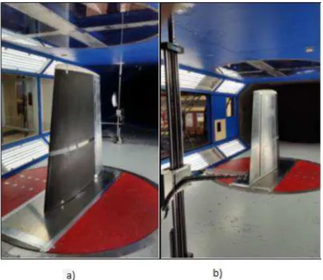
The wind tunnel tests were performed at the National Research Council Canada in the 2 m x 3 m atmospheric closed circuit subsonic wind tunnel. This atmospheric wind tunnel can operate at a maximum Mach number of 0.33.
Figure 6 presents the MDO 505 CRIAQ project morphing wing model installed in the tunnel test section, viewed from both its leading edge (Figure 6a) and its trailing edge (Figure 6b).
The wing model equipped with the morphing aileron at the trailing edge is shown in Figure 7.
Figure 6. MDO 505 wing model setup in the wind tunnel test section
b. Data Measurement Tools
The upper surface flexible skin of the wing demonstrator was equipped with 32 high precision Kulite piezoelectric-type transducers, for pressure measurement on the flexible skin and the data was processed to determine the laminar-to-turbulent flow transition location. These sensors were installed in two staggered lines (with 16 Kulite sensors on each line), situated respectively at 0.600 m and 0.625 m from the wing root section. In addition to the Kulite piezoelectric sensors, 60 static pressure taps were installed (30 taps on each line), on the wing leading edge, lower surface and aileron, thus providing complete experimental pressure distribution around the wing cross section at 40% of the wing span. The pressure sensors were installed in a staggered fashion in order to minimize the interference between them.
Infra-red (IR) thermography camera visualizations were performed for capturing the transition region over the entire wing model surface. The wing leading edge, its upper surface flexible skin, and the aileron interface were coated with high emissivity black paint to improve the quality of the IR photographs. The span-wise stations, where the two pressure sensors lines were installed, were not painted, in order to ensure the pressure reading high quality35.
The IR thermography visualization allowed the identification of the transition region between laminar and turbulent regimes, based on the analysis of the model surface temperature. The turbulent flow regime increases the convective heat transfer between the model and the flow with respect to the laminar boundary layer. A flow temperature change, introduced by the wind tunnel heat exchanger system, will cause different temperature changes over the model, depending on the behavior of the boundary layer.
The experimental measurements also included the use of a wake rake pressure acquisition system, with the aim to measure the wing profile drag at different span-wise positions, and to use a wind tunnel balance for measuring the aerodynamic forces and moments.
In order to avoid the possibility of damaging the wing tip model during wind tunnel testing, and to be able to observe the wing vibration behaviour, three accelerometers were installed. The three accelerometers were installed on the wing box, aileron and wind tunnel balance respectively as shown in Figure 7.
Figure 7. Positions and orientations of the accelerometers on the wing
6. Results
During the wind tunnel test sessions, 49 flight cases were tested for the wing demonstrator equipped with morphing wing upper-surface and morphing aileron. For all these flight cases, the optimization was performed in advance of the wind tunnel tests, and the optimization objectives were the delay of the flow transition from the laminar to turbulent states. From the 49 cases tested, 32 cases will be presented here, that are shown in Table 1.
Table 1. 32 flight cases tested in wind tunnel tests for the wing tip demonstrator with both morphing wing upper surface and morphing aileron
Case No Mach number
Wing geometrical Angle of Attack (°) Adaptable Aileron Deflection (°) 1 0.15 -3 -4.01 2 0.15 0.5 -4.01 3 0.15 1 -4.01 4 0.15 1.5 -4.01 5 0.15 -0.5 -1.13 6 0.15 -0.25 -1.13 7 0.15 0 -1.13 8 0.15 0.25 -1.13 9 0.15 0.5 -1.13
10 0.15 0.75 -1.13 11 0.15 1 -1.13 12 0.15 1.25 -1.13 13 0.15 1.5 -1.13 14 0.15 2 -1.13 15 0.15 3 -1.13 16 0.2 0 -1.13 17 0.2 0.5 0.03 18 0.2 1 0.03 19 0.2 1.5 0.03 20 0.2 2 0.03 21 0.20 -1.4 0.03 22 0.20 -0.9 0.03 23 0.20 -0.5 -0.24 24 0.20 0.6 -0.24 25 0.20 0.00 -0.24 26 0.20 0.50 -0.5061 27 0.20 1.00 0.03 28 0.20 1.50 0.03 29 0.20 2.00 0.03 30 0.15 0 0.03 31 0.15 0 0.03 32 0.15 0 1.60
In order to ensure that the aileron was morphed to its desired shape, the experimental pressure distribution of the demonstrator, with both its wing upper surface and its aileron actively morphed, was compared with the equivalent numerical pressure distribution.
Figure 8 and Figure 9 present the comparison between the numerical and experimental pressure distribution of the wing tip demonstrator with both wing upper surface and aileron actively morphing for the 1st and 21st case given in Table 1. It can be observed that the two pressure distributions show a very good match, so that the aileron had its desired shape during wind tunnel tests.
Figure 9 Numerical versus Experimental Pressure Distribution for Case 21
a. Experimental transition optimization comparison
In order to evaluate the optimization success of the wing tip demonstrator, the experimental transition region of the morphed wing tip demonstrator (both upper surface and aileron) was compared to the experimental transition of the un-morphed wing tip demonstrator. The experimental transition region was provided by the Infra-Red Thermography data that was recorded during each of the flight case wind tunnel testing. An example of Infra-Red Thermography images is given in figure 10 (a) for the un-morphed wing tip and in Figure 10 (b) for the morphed wing tip. The results obtained for the case 26 are presented in figure 10.
Figure 10. Infrared images of the laminar, transition and turbulent regions on the upper surface of the wing for case 26
The region delimited by the white interrupted lines represents the transition region on the upper surface of the wing. The black line represents the average or medium section of this region.
The left white interrupted line represents the border between the laminar region and the transition region. This line was named ‘lower boundary’ and any modification in the position of
this line was considered as an ‘extension of the laminar region’ (λ). The extension could be positive if the line moves towards the trailing edge, or negative if the line moves towards the leading edge.
The far right white interrupted line represents the border between the fully turbulent region and the transition region. This line was named ‘upper boundary’ and any modification in the position of this line was considered as a ‘contraction of the turbulent region’ (τ). As with the
extension of the laminar region λ, this parameter can be positive, if the line moves towards the
trailing edge, which signifies a smaller turbulent region on the wing, or negative if the line moves towards the leading edge, which signifies an enlargement of the turbulent region.
The length of the transition region can be affected by the values of λ and τ. The width of the
transition region can be calculated as the difference between λ and τ.
From the 32 flight cases presented in Table 1, 31 cases have given a positive extension of the
laminar region coupled with a positive contraction of the turbulent region.
Table 2 presents the values of λ, τ and the difference between the average lines of the un-morphed and un-morphed transition region for all 32 cases.
Table 2 Presentation of τ and λ parameters for each of the flight cases from Table 1
Case No Extension of the Laminar
region (% of chord) (λ)
Transition Region average (% of chord)
Contraction of the turbulent region (% of chord) (τ) 1 1.38 2.88 4.38 2 2.84 3.84 4.84 3 2.28 2.28 2.28 4 4.84 3.84 2.84 5 0.92 1.92 2.92 6 1.47 1.97 2.47 7 1.98 2.68 3.38 8 0.30 1.30 2.30 9 3.09 2.09 1.09 10 5.15 4.15 3.15 11 0.51 0.51 0.51 12 2.06 2.06 2.06 13 2.90 2.90 2.90 14 3.00 3.00 3.00 15 0.65 0.65 0.65 16 2.54 2.54 2.54 17 3.74 3.74 3.74 18 6.43 6.43 6.43 19 1.52 4.02 6.52 20 1.29 1.29 1.29 21 1.80 0.80 -0.20 22 3.87 2.87 1.87
23 1.71 1.71 1.71 24 2.54 3.54 4.54 25 1.66 2.66 3.66 26 0.64 2.64 4.64 27 3.79 3.29 2.79 28 6.80 5.80 4.80 29 5.04 4.54 4.04 30 3.40 3.90 4.40 31 1.30 0.80 0.30 32 0.91 1.41 1.91
There are two cases, flight case 11 and flight case 15, that have both (λ) and (τ) with values
less than 1% of the chord. For these two cases, it was concluded that neither the morphing aileron nor the morphing upper surface skin had any notable influence on the behaviour of the flow.
Flight case 21 gave a small negative contraction of the turbulent region (τ) that is
counterbalanced by almost 2% of the chord of laminar region extension.
The other flight cases gave an extension of the laminar region λ of up to 7% of the chord, and
a contraction of the turbulent region τ of up to 6.5% of the chord.
The variation of upper and lower boundaries of the transition region in percentage of chord versus the wind tunnel case is shown in Figures 11 to 14. In these figures, it can be clearly observed the modification of the transition region (its upper and lower boundaries) between un-morphed and un-morphed states towards the trailing edge section of the wing. This delay is due to both upper surface skin and aileron morphing that occurred for the specific actuators and aileron angles displacements.
Figure 11 Comparison between the experimental transition regions of the morphed and un-morphed wing tip demonstrator – Cases 1 to 8
Figure 12 Comparison between the experimental transition regions of the morphed and un-morphed wing tip demonstrator - Cases 9 to 16
30,00% 35,00% 40,00% 45,00% 50,00% 55,00% 60,00% 65,00% 70,00% 0 2 4 6 8 10 Upp e r & Low e r B o u n d ar ie s (% c) Case number Umorphed Wing Morphed Wing 30,00% 35,00% 40,00% 45,00% 50,00% 55,00% 60,00% 65,00% 70,00% 9 11 13 15 17 Upp e r & Low e r B o u n d ar ie s (% c) Case number Umorphed Wing Morphed Wing
Figure 13 Comparison between the experimental transition regions of the morphed and un-morphed wing tip demonstrator – Cases 17 to 25
Figure 14 Comparison between the experimental transition regions of the morphed and un-morphed wing tip demonstrator – Cases 26 to 32
The morphing aileron results were also compared with the baseline (un-morphed) configuration for different morphing deflections: lift versus angle of attack (CL-α). (Figure 15); drag polars (CD-CL) (Figure 16). The first one shows a typical linear trend. The curve slope (CLα) remains unchanged and the camber increase (high α0L) with the morphing deflections
30,00% 35,00% 40,00% 45,00% 50,00% 55,00% 60,00% 65,00% 70,00% 16 18 20 22 24 Upp e r & Low e r B o u n d ar ie s (% c) Case number Umorphed Wing Morphed Wing 30,00% 35,00% 40,00% 45,00% 50,00% 55,00% 60,00% 65,00% 70,00% 24 26 28 30 32 Upp e r & Low e r B o u n d ar ie s (% c) Case number Umorphed Wing Morphed Wing
(from baseline to 6 deg) by moving the curves upwards. The aerodynamic polars cross in correspondence of a pivot point for high CL and move to the right side of the Cartesian plane for low CL, enveloping an optimal curve maximizing aircraft aerodynamic efficiency throughout the aircraft cruise.
Figure 15 Lift coefficient versus angle of attack curve
Figure 16 trend of the Drag polars with increasing morphing angles
Conclusions
In the present paper, an interdisciplinary project done in the frame of an international collaboration between Canada and Italy was presented. A wing tip demonstrator was equipped
with a composite flexible upper surface capable to sustain deformations under the action of four electrical actuators. The wing-tip was also equipped with an innovative morphing aileron, capable of deflecting to a predetermined shape designed to improve the pressure distribution and in general the flow circulation around the wing. The objective of the project was the development and testing of a wing tip demonstrator equipped with both morphing components, while respecting structural constraints similar to those imposed for real aircraft wings. The internal structure distribution and the components of the wing tip demonstrator were similar to those of a real wing tip structure.
During wind tunnel tests, the objective was to actively change both the upper surface and the aileron shapes for various wind tunnel cases with the purpose to delay the flow transition from the laminar to the turbulent state. The deformation was performed based on a database of actuator displacements and morphing aileron deflection shapes. The database was obtained from the numerical optimization of the wing’s airfoil using a genetic algorithm optimizer coupled with cubic spline reconstruction and with the XFoil solver for fast aerodynamic calculation.
The experimental results have shown that the morphing aileron was capable of obtaining the desired shape, as it resulted from the pressure distribution comparison. The objective of flow transition delay was obtained for all 32 flight cases presented in this paper, with the maximum delay of the flow transition occurring at 7% of the chord. These results show the success of the numerical optimization carried at the airfoil level and the possibilities that could be explored with a coupled morphing upper surface and morphing aileron wing.
Acknowledgements
We would like to thank to Bombardier Aerospace, Thales Canada, The Consortium in Research and Aerospace in Canada (CRIAQ), and to the Natural Sciences and Engineering Research Council of Canada (NSERC) for their financial support. Special thanks are dues to our collaborators and leaders in this project: Mr. Patrick Germain and Mr. Fassi Kafyeke from Bombardier Aerospace, Mr. Eric Laurendeau from Ecole Polytechnique, Mr. Philippe Molaret from Thales Canada, and Mr. Erik Sherwood and his team from DFS-NRC for the wing model design and fabrication.
Bibliography
1United States Navy, “F-14 Tomcat fighter fact file”, 5 July 2003, retrieved: 20 January
2007, cited in May 2016
2Talay, Th. A., ed. (2003) “Dynamic Longitudinal, Directional, and Lateral Stability”,
Centennial of Flight Commission, 2003, retrieved: 24 May 2011, cited in May 2016
3Bonnema, K. L., & Smith, S. B., (1998) “AFTI/F-111 mission adaptive wing flight research program”, Report, San Diego, California, pp. 155 – 161, 1988
4Sofla, A. Y. N., Meguid, S. A., Tan, K. T., & Yeo, W. K. (2010). “Shape morphing of aircraft wing: status and challenges”. Materials & Design, 31(3), 1284-1292.
5Barbarino, S., Bilgen, O., Ajaj, R. M., Friswell, M. I., & Inman, D. J. (2011). “A review of morphing aircraft”, Journal of Intelligent Material Systems and Structures, 22(9), 823-877.
6Gabor, O. S., Koreanschi, A., & Botez, R. M. (2013). “Optimization of an Unmanned Aerial Systems' Wing Using a Flexible Skin Morphing Wing”, SAE International Journal of Aerospace,
6(2013-01-2095), 115-121.
7Gabor, S., Koreanschi, A., & Botez, R. M. (2014) “Numerical optimization of the S4 Éhecatl UAS airfoil using a morphing wing approach”, In American Institute of Aeronautics and
Astronautics AIAA 32nd Applied Aerodynamics Conference, 16-20 June 2014, Atlanta, Georgia, USA.
8Botez, R. M., Molaret, P., & Laurendeau, E.,(2007) “Laminar flow control on a research wing project presentation covering a three year period”, Canadian Aeronautics and Space
Institute Annual General Meeting, 2007, Ottawa, Ont., Canada.
9Grigorie, T. L., Popov, A. V., Botez, R. M., Mamou, M., & Mébarki, Y.,(2010) “A Morphing Wing used Shape Memory Alloy Actuators New Control Technique with Bi-positional and PI Laws Optimum Combination - Part 1: Design Phase.”, ICINCO 2010,
Proceedings of the 7th International Conference on Informatics in Control, Automation and Robotics, Volume 1, Funchal, Madeira, Portugal, June 15-18.
10Grigorie, T. L., Popov, A. V., Botez, R. M., Mamou, M., & Mébarki, Y.,(2010) “A Morphing Wing used Shape Memory Alloy Actuators New Control Technique with Bi-positional and PI Laws Optimum Combination - Part 2: Experimental Validation.”, ICINCO
2010, Proceedings of the 7th International Conference on Informatics in Control, Automation and Robotics, Volume 1, Funchal, Madeira, Portugal, June 15-18
11Coutu, D., Brailovski, V., & Terriault, P., (2009) “Promising Benefits of an Active-Extrados Morphing Laminar Wing”, Journal of Aircraft, Vol. 46, No. 2, pp. 730-731, March-April.
12Courchesne, S., Popov, A. V., & Botez, R. M., (2010) “New aeroelastic studies for a morphing wing”, 48th AIAA Aerospace Sciences Meeting including The New Horizons Forum
and Aerospace Exposition, Orlando, Florida, USA, 2010.
13Popov, A.V., Botez, R.M., Grigorie, T. L., Mamou, M., & Mebarki, Y., (2010) “Real time airfoil optimization of a morphing wing in wind tunnel”, AIAA Journal of Aircraft, Vol. 47(4),
pp. 1346-1354, 2010.
14Popov. A-V., Labib, M., Fays, J., & Botez, R.M., (2008) “Closed loop control simulations on a morphing laminar airfoil using shape memory alloys actuators”, AIAA Journal of Aircraft, Vol.
45(5), pp. 1794-1803, 2008.
15Popov, A.V., Botez, R.M., Grigorie, T. L., Mamou, M., & Mebarki, Y., (2012) “On–off and proportional–integral controller for a morphing wing. Part 1: Actuation mechanism and control design”, Journal of Aerospace Engineering, February 2012; vol. 226, 2: pp. 131-145., first
published on November 21, 2011
16Grigorie, L. T., & Botez, R. M., “Adaptive neuro-fuzzy inference system-based controllers for smart material actuator modelling”, Journal of Aerospace Engineering, vol. 223, 6: pp. 655-668.
, June 1, 2009
17Grigorie, L.T., Botez, R.M., & Popov, A.-V., “Adaptive neuro-fuzzy controllers for an open loop morphing wing system”, Journal of Aerospace Engineering, Vol. 223(J), pp. 965-975,
18Wölcken, P.C., Papadopoulos, M., “Smart Intelligent Aircraft Structures (SARISTU)”,
Proceedings of the Final Project Conference, Springer 2015 ISBN 978-3-319-22413-8
19Koreanschi, A., Sugar, O., & Botez, R. M. (2015) “Drag Optimization of a Wing Equipped with a Morphing Upper Surface”, Royal Aeronautical Journal, March 2016, Vol. 120, No. 1225,
pp.473-493, doi: 10.1017/aer.2016.6
20Michaud, F., Joncas, S., & Botez, R. M. (2013) “Design, Manufacturing and Testing of a Small-Scale Composite Morphing Wing”, In 19th International Conference on Composite
Materials, Montréal, Québec, Canada, July.
21Koreanschi, A., Henia, M. B., Guillemette, O., Michaud, F., Tondji, Y., Gabor, O. S., & Salinas, M. F. (2016). “Flutter Analysis of a Morphing Wing Technology Demonstrator: Numerical Simulation and Wind Tunnel Testing”, INCAS Bulletin, 8(1), 99.
22Kammegne, M. J. T., Nguyen, D. H., Botez, R. M., & Grigorie, T. L. (2015) “Control validation of a morphing wing in an open loop architecture”, AIAA Modeling and Simulation
Technologies Conference, Aviation Forum.
23Kammegne, Michel Joël Tchatchueng, Hamdi Belhadj, Duc-Hien Nguyen, & Ruxandra Mihaela Botez. (2015) "Nonlinear Control Logic for an Actuator to Morph a Wing: Design and Experimental Validation." IASTED Modelling, Identification and Control Conference, 2015. 24Pecora, R., Barbarino, S., Concilio, A., Lecce, L., & Russo, S., (2011) ”Design and Functional Test of a Morphing High-Lift Device for a Regional Aircraft”, Journal of Intelligent Material
Systems and Structures, Vol. 22, no. 10, pp. 1005-1023, 2011
25
Barbarino, S., Pecora, R., Lecce, L., Concillio, A., Ameduri, S., & De Rosa, L., “Airfoil structural morphing based on SMA actuator series: numerical and experimental studies”, Journal
of Intelligent Material Systems and Structures, Vol. 22, pp. 987-1003, 2001
26Ameduri, S., Brindisi, A., Tiseo, B., Concilio, A., & Pecora, R., (2002) “Optimization and integration of shape memory alloy (SMA) based elastic actuators within a morphing flap architecture”, Journal of Intelligent Material Systems and Structures, Vol. 23, issue 4, pp.
27Dimino, I., Flauto, D., Diodati, G., Concilio, A., Pecora, R., “Actuation System Design for a Morphing Wing Trailing Edge,” Recent Patents on Mechanical Engineering, Volume 7, pp
138-148, (2014)
28Diodati, G., Concilio, A., Ricci, S., de Gaspari, A., Liauzun, C., & Godard, J.L., (2013) “Estimated performance of an adaptive trailing-edge device aimed at reducing the fuel consumption on a medium-size aircraft”, Smart Structures/NDE conference, 10-14 March 2013,
San Diego, California,USA, 2013
29G. Amendola, I. Dimino, M. Magnifico and R. Pecora (2016) “Distributed actuation concepts for a morphing aileron device”. The Aeronautical Journal, Vol. 120, pp 1365-1385 doi:10.1017/
aer.2016.64
30Koreanschi, A., Sugar-Gabor, O., & Botez, R.M., (2016) “Numerical and Experimental Validation of a Morphed Wing Geometry Using Price-Paidoussis Wind Tunnel Testing”, The
Aeronautical Journal
31Gabor, O. S., Koreanschi, A., & Botez, R. M. (2012) “Low-speed aerodynamic characteristics improvement of ATR 42 airfoil using a morphing wing approach” In IECON 2012-38th Annual
Conference on IEEE Industrial Electronics Society (pp. 5451-5456). IEEE.
32Koreanschi, A., Şugar Gabor, O., Acotto, J., Brianchon, G., Portier, G., Botez, R.M., Mamou, M., & Mebarki, Y., (2016) “Optimization and Design of a Morphing Aircraft Wing Tip Demonstrator for Drag Reduction at Low Speed, Part I – Aerodynamic Optimization Using 3 Algorithms: Genetic, Bee Colony and Gradient Descent”, This article was submitted to The
Chinese Journal of Aeronautics
33Koreanschi, A., Sugar Gabor, O., Ayrault, T., Botez, R.M., Mamou, M., & Mebarki, Y., (2016) “Numerical Optimization and Experimental Testing of a Morphing Wing with Aileron System”,
In 24th AIAA/AHS Adaptive Structures Conference. p. 1083
34Koreanschi, A., Sugar-Gabor, O., & Botez, R. M. (2014). “New Numerical Study of Boundary Layer Behavior on A Morphing Wing-with-Aileron System”, In 32nd AIAA Applied
35Mebarki, Y., Mamou, M., & Genest, M. (2009), “Infrared Measurements of the Transition Detection on the CRIAQ Project Morphing Wing Model” NRC LTR AL-2009-0075