Publisher’s version / Version de l'éditeur:
Vous avez des questions? Nous pouvons vous aider. Pour communiquer directement avec un auteur, consultez la première page de la revue dans laquelle son article a été publié afin de trouver ses coordonnées. Si vous n’arrivez pas à les repérer, communiquez avec nous à PublicationsArchive-ArchivesPublications@nrc-cnrc.gc.ca.
Questions? Contact the NRC Publications Archive team at
PublicationsArchive-ArchivesPublications@nrc-cnrc.gc.ca. If you wish to email the authors directly, please see the first page of the publication for their contact information.
https://publications-cnrc.canada.ca/fra/droits
L’accès à ce site Web et l’utilisation de son contenu sont assujettis aux conditions présentées dans le site LISEZ CES CONDITIONS ATTENTIVEMENT AVANT D’UTILISER CE SITE WEB.
Symposium on Advance in Fire Suppression Technologies [Proceedings], pp. 1-11, 2005-10-01
READ THESE TERMS AND CONDITIONS CAREFULLY BEFORE USING THIS WEBSITE.
https://nrc-publications.canada.ca/eng/copyright
NRC Publications Archive Record / Notice des Archives des publications du CNRC :
https://nrc-publications.canada.ca/eng/view/object/?id=7d412457-ad74-4184-b5db-2663c206ac1d https://publications-cnrc.canada.ca/fra/voir/objet/?id=7d412457-ad74-4184-b5db-2663c206ac1d
NRC Publications Archive
Archives des publications du CNRC
This publication could be one of several versions: author’s original, accepted manuscript or the publisher’s version. / La version de cette publication peut être l’une des suivantes : la version prépublication de l’auteur, la version acceptée du manuscrit ou la version de l’éditeur.
Access and use of this website and the material on it are subject to the Terms and Conditions set forth at
Development of a low pressure water mist system for industrial oil cooker protection
Development of a low pressure water mist system for industrial oil cooker protection
Yen, P.L.; Liu, Z.; Carpenter, D.; Kim, A.K.
NRCC-47675
A version of this document is publishing in / Une version de ce document se trouve dans: Symposium on Advance in Fire Suppression Technologies, San Diego, CA., U.S.A.,
Oct. 18-19, 2005, pp. 1-11
DEVELOPMENT OF A LOW PRESSURE WATER MIST SYSTEM FOR INDUSTRIAL OIL COOKER PROTECTION
Yen, P. L.
CAFS Units, Inc., Arcadia, CA, 91006, USA, E-mail: cafsunit@sbcglobal.net Liu, Z., Carpenter, D. and Kim, A. K.
Fire Research Program, Institute for Research in Construction National Research Council of Canada, Ottawa, Canada, K1A 0R6 INTRODUCTION
Industrial oil cookers are found in many major food production plants for
processing chicken, fish, potato products, doughnuts and other food products. They have large cooking surfaces and contain tens of thousands of liters of hot oil. Large fires could occur in industrial oil cookers by overheated oil to its auto-ignition temperature due to a system malfunction or simple human error [1]. These fires are difficult to extinguish, and present a severe hazard to the food processing plant as the fires spread rapidly over the oil surface and grow to large sizes. To extinguish the fire, it requires flame extinction over the entire surface at once, and at the same time, rapid cooling of the oil to below its auto-ignition temperature to prevent it from re-auto-ignition.
Fire suppressants that contain chemical components are not allowed to be used in the food processing industry due to considerations of food safety. Previous research showed that sprinkler water sprays were able to extinguish industrial oil cooker fires, but a large amount of oil was spilled over the oil cooker and formed large fires on the ground, as coarse water droplets sank and boiled up in the hot oil [2]. Carbon dioxide is
commonly used for industrial oil cooker protection. It is capable of extinguishing flames over the oil surface, but it cannot effectively prevent hot oil from re-ignition due to its limited cooling capacity.
CAFS Units, Inc., with the National Research Council Canada (NRC), has developed a low pressure water mist fire suppression system (MistShield), ranging from 4.1 bar (60 psi) to 6.9 bar (100 psi), for industrial oil cooker protection. Its extinguishing performances associated with four different sizes of industrial oil cookers have been evaluated in full-scale fire tests following FM Global’s fire testing protocols [1]. The system effectively extinguished large cooking oil pool fires in less than 12 s and
prevented re-ignition by cooling a large quantity of hot oil to below its flashing point. No oil was splashed outside the cooking equipment during the fire suppression. The system has successfully passed through the fire test protocols required for industrial oil cooker protection. This paper will discuss the characteristics of the MistShield water mist system and report its extinguishing performances against large cooking oil pool fires.
MISTSHIELD SYSTEM AND ITS SPRAY CHARACTERISTICS
The water mist system consists of a number of MistShield nozzles and a piping system. The MistShield nozzle is an open (non-automatic), single fluid pressure-type spray nozzle that is assembled with seven removable spray caps. Its operating pressure ranges from 414 kPa (60 psi) to 689 kPa (100 psi) and the water flow rate from 28.2 L/min at 414 kPa to 39 L/min at 689 kPa discharge pressure. The water drops generated are relatively fine. Under a pressure of 552 kPa (80 psi), 50% and 90% of the spray volume in drops are smaller than 250 and 380 μm, respectively. The spray angle of the nozzle is 150 degrees and is not changed with an increase in discharge pressure. Its spray coverage is approximately 2.8 m in diameter
when the discharge distance of the nozzle to the oil surface is 1.0 m. The water spray generated by a MistShield nozzle is shown in Figure 1.
Figure 1. Water spray of a single MistShield nozzle
For the protection of an industrial oil cooker, the nozzles of the MistShield system were installed in a vertical downward orientation inside the protected oil cooker. Each nozzle was located at the center of its coverage area and 0.93 m (3 ft) from the bottom of the oil pan. The maximum area that could be protected by a single
MistShield nozzle was 1.22 m wide x 1.22 m long and extended to 1.22 m wide x 1.52 m long in a multiple-nozzle application as shown in Figure 2. The number of nozzles installed in an oil cooker was determined by the size of the cooker.
The water density distributions of a single nozzle and a group of nozzles over the oil pools were measured. The total amount of water collected in the pan was measured by measuring the water depth in the pan. The water collection ratio in the pan was defined as the ratio of total water collected in the pan to the total water discharged by the water mist system.
Experimental results showed that water mist generated by the system was able to cover the whole oil pan surface. Figure 3 shows the water density distribution over the pan (2.4 m wide by 3.0 m long) with 4 nozzles under 552 kPa discharge pressure (x-axis is the distance from the center of the pan). It was different from that generated by a single nozzle due to the overlap of water mist. Higher water density was distributed underneath the nozzles and the areas between the nozzles where water spray overlaps. The water density at the corner of the pan was the lowest (5.2 kg/m2.min at 5.5 bar), while water density at the center of the pan (12.1 kg/m2.min at 5.5 bar) was two times higher than that at the corner of the pan.
Distance from the Center of the Pan (cm) 0 20 40 60 80 100 120 140 160 180 200 W a te r Dens it y in Oil P an (k g/m 2.min) 0 5 10 15 20 25 30 35 40 diag (60 psi) long (60 psi) trans (60 psi) diag (100 psi) long (100 psi) trans (100 psi)
Figure 2. Schematic of a group of MistShield nozzles and their protected areas
Figure 3. Water density distribution of MistShield system in the oil pan under two discharge pressures
Under 414 kPa discharge pressure, the total water flow rate of the system was 112.8 L/min and approximately 84.2% of discharged water was collected by the pan. The average water density in the pan was 13.2 kg/m2.min. With an increase in discharge pressure, the water delivery densities in the pan increased but its spray coverage pattern and water collection ratio did not change because there was no change in its spray angle, as shown in Figure 3.
INDUSTRIAL OIL COOKER MOCK-UPS
Four industrial oil cooker mock-ups were built. They were used to investigate the impact of oil cooker sizes on the performance of water mist. The oil cooker mock-up consisted of a pan and a hood. Both ends of the hood were open. The schematics of four mock-ups #1 through #4, are shown in Figures 4 to 7.
Oil pans #1 to #3 had the same width (1.22 m) and depth (0.343 m), but their lengths were 1.22 m, 3.05 m and 4.57 m, respectively. Their hoods also had the same width (1.27 m) and depth (0.76 m) but the lengths of the three hoods were 1.27 m, 3.10 m and 4.62 m, respectively. There were holes with a dimension of 0.508 m in diameter on top of the hood to simulate the connection with the exhaust duct. The number of holes on top of the hood was determined according to the length of the hood.
Figure 4. Schematic of industrial oil cooker mock-up #1 (dimensions in the figure are in mm)
Figure 6. Schematic of industrial oil cooker mock-up #3 (dimensions in the figure are in mm)
Figure 5. Schematic of industrial oil cooker mock-up #2 (dimensions in the figure are in mm)
1525
2600 3050
2400
3000
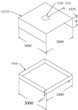
Figure 7. Schematic of industrial oil cooker mock-up #4 (dimensions in the figure are in mm)
Mock-up #4 pan was 3.0 m long, 2.4 m wide and 0.343 m deep. Its hood was 3.05 m long, 2.6 m wide, and 0.76 m deep. There was a 0.508 m diameter hole on top of
the hood at the center. The distance from the center of the hole to either end of the hood was 1.5 m.
During the experiments, the effect of the hood position in the oil cooker on the water mist extinguishing performance was also investigated. The hood was placed in two different positions: a hood-up and a hood-down position. The clearance of the gap
between the hood and the pan was 0.46 m at the up position and 0.05 m at the hood-down position.
A propane burner system was used as the heating source for the mock-ups. The burner system was centered beneath the pan, distributing the heat uniformly throughout the pan surface.
INSTRUMENTATION
A number of instruments were used in the experiments to monitor the water mist discharge and fire suppression process. They were thermocouples, pressure gauges, heat flux meters, oxygen analyzers, water flow meters and video cameras.
For experiments involving industrial oil cooker Mock-ups #1 to #3, a number of thermocouple trees were used to measure oil and flame temperatures. The thermocouple trees were placed along the centerline of the mock-up. Each thermocouple tree had two thermocouples that were located, respectively, 5.1 cm and 10.2 cm above the bottom of the pan. The number of thermocouple trees and their locations in the pan were
determined by the size of the oil cooker mock-up. One thermocouple tree was used in the tests with Mock-up #1 to measure the oil temperatures. It was located at 0.61 m from the edge of the pan. Four thermocouple trees were used in the tests with Mock-up #2 to measure the oil temperature. They were located at 0.61 m intervals starting at 0.61 cm from the end of the pan. One extra thermocouple was placed at thermocouple tree #2 and 0.22 m above the bottom of the pan, which was used to determine the oil ignition
temperature and ignition time. Seven thermocouple trees were used in the tests with Mock-up #3. They were located at 0.61 m intervals starting at 0.45 m from the end of the pan. Also, one extra thermocouple was placed at thermocouple tree #2 and 0.22 m above the bottom of the pan, which was used to determine the oil ignition temperature and ignition time.
For experiments involving Mock-up #4, three thermocouple trees were placed in the pan to measure oil temperatures and air/flame temperatures above the oil surface. Thermocouple tree #1 was placed in the center of the pan and thermocouple trees #2 and #3 were located 0.7 m apart from each other along the direction from the center of the pan to the southeast corner of the pan. Eight thermocouples (Type K, 18 gauge) were attached to each tree. The elevation of each thermocouple was 51, 100, 124, 165, 254, 381, 681 and 981 mm, respectively, above the bottom of the pan, when the oil depth was 127 mm.
Two pressure gauges were used to monitor the discharge pressure of the water mist system. The first one was located in the inlet of the water mist piping system and another was located near one of the nozzles. The real discharge pressure was determined based on the data measured near the nozzle.
Two heat flux meters (air-cooled) were used to measure the radiation of the fire and to determine if fire flare-ups were generated during the suppression. The heat flux meters were located 0.5 m away from the pan at 1.2 m and 1.90 m above the floor.
Three video cameras were used in the experiments to record the testing process and to assist in the identification of the water mist discharge time as well as the fire extinguishing time. One was located at the southeast side of the cooker, the second at the west side of the cooker, and the third was an aerial-view camera and elevated 7 m from the ground of the east side of the cooker.
One O2 analyzer was used to measure the O2 concentration in the compartment.
The sampling port was located at the east side of the up, 1 m away from the mock-up and 0.05 m above the edge of the pan.
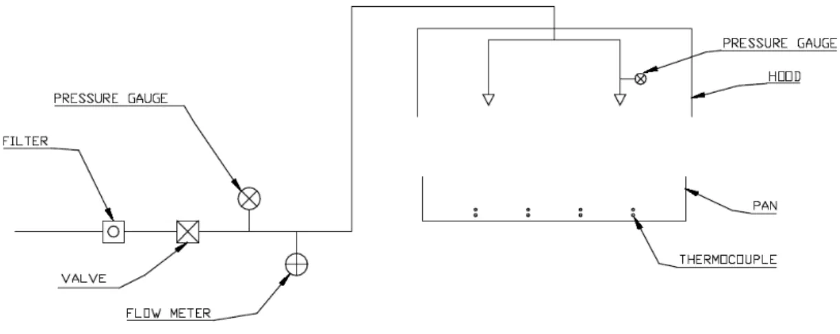
One flow meter located in the inlet of the water mist system was used to measure the water flow rate of the water mist system. The locations of thermocouples, pressure gauges and water flow meter are shown in the schematic of the instrumentation (see Figure 8).
Figure 8. Schematic of instrumentation in the fire tests
The experiments were conducted following FM Global’s fire testing protocols [1]. During the experiments, all testing data, including temperature, pressure, heat flux and water flow rate, were collected by a data acquisition system.
EXPERIMENTAL PROCEDURE
Canola oil was used as the cooking oil in the experiments. The properties of the canola oil in the room temperature are listed in Table 1.
Table 1. Physical Property of Canola Oil [2, 5]
Oil Flash Point
(C) Auto-ignition temperature (C) Density (kg/L) Specific heat (kJ/kg.K) Heat release rate (MW/m2) Canola 232-290 330-360 0.914 1.91 1.81
Fresh cooking oil was introduced into the pan for each experiment and then heated continuously at 3-5oC/min until it auto-ignited. After the flame had spread over the whole oil surface, the fire was allowed to burn freely for 30 seconds. At the end of the pre-burning period, the water mist discharge was activated manually. After the fire was extinguished, the discharge of water mist was maintained for a certain time period to cool the cooking oil and prevent re-ignition.
During the approval experiments, the performance of the water mist system was evaluated with three sizes of the industrial oil cooker mock-ups. There were two
experiments for each size of industrial oil cooker mock-up associated with two different hood positions. Water mist system components, their locations and operating conditions remained unaltered throughout the experiments.
FIRE EXPERIMENTS
The extinguishing performance of the MistShiled water mist system was evaluated in the experiments by using different sizes of industrial oil cooker mock-ups with different hood positions, discharge pressures and oil depth. The discharge pressure employed in the experiments ranged from 414 kPa (60 psi) to 689 kPa (100 psi). Some experimental conditions and results are listed in Table 2.
Table 2: Experimental Conditions and Results of MistShield Water Mist System Test
No.
Cooker Oil depth (cm) Discharge press. (psi) Hood position Pre-burn period (s) Ignition temp. (C) Ext. time (s) Discharge duration (s) T1-1 #4 5.1 100 Up 38 356 4 20 T1-2 #4 5.1 60 Up 34 356 7 25 T1-5 #4 5.1 60 Down 35 357 5 22 T1-6 #4 12.5 60 Down 36 350 5 24 T1-7 #4 12.5 60 Up 42 351 7 23 T2-1 #1 12.5 100 Up 30 356 11 78 T2-2 #1 12.5 100 Down 30 355 4 88 T2-3 #2 12.5 100 Up 30 356 5 88 T2-4 #2 12.5 100 Down 30 348 4 83 T2-5 #3 12.5 100 Up 30 359 11 77 T2-6 #3 12.5 100 Down 31 356 3 89
During the experiments, fresh canola oil was heated continuously. After the oil was heated over 250oC, smoke appeared over the oil surface. The smoke and fuel vapour became very dense near the auto-ignition temperature. The oil auto-ignited at
temperatures ranging from 343oC to 361oC during the experiments. The flame consumed all the fuel vapour over the oil surface that was generated in the heating period and quickly spread to the whole oil surface. During free burning, the fire was fully
developed, filling inside the cooker and reaching outside the hood. A large amount of dark smoke was produced. The flame temperatures were high at the center of the oil pan and they decreased with an increase in distance from the center of the oil pan.
Full-scale experiments showed that the MistShield water mist system effectively extinguished all the large cooking oil fires in the experiments. No excessive fire flare-up was produced and no burning oil was splashed outside the cooking equipment during fire suppression. With the discharge of water mist, the flame below the nozzle tip was quickly extinguished and dark smoke disappeared from the cooker as fine water drops absorbed the heat from the hot oil and produced a large amount of steam (Figure 9). The entire flame in the oil cooker was completely extinguished after a certain period of water mist discharge. Its extinguishing time ranged from 3 to 11 s, depending on the discharge pressure, oil cooker size, and hood position, but independent of the oil depth in the pan.
Figure 9. A cooking oil fire was suppressed by the water mist system (Mock-up #3)
Time (s) 100 200 300 400 500 600 700 Thermocouple location 1955 1960 1965 1970 1975 1980 1985 T emp era ture ( oC) 16.5 cm 38.1 cm 98.1 cm discharge extinguishing end of discharge
Figure 10. Variation of gas temperatures above oil surface with time
Figure 10 shows variations of the air and flame temperature with time in Test T1-7. Once the water mist discharge was activated, the temperatures below the nozzle tip quickly dropped as fine water drops cooled and extinguished the flame, while the temperature above the nozzle tip suddenly increased as some flames were pushed up. The gas temperature near the ceiling of the oil cooker was decreased more slowly than those at the lower portion of the oil cooker. After the fire was extinguished, the gas temperatures far from the oil surface were cooled down to around 80oC and tended to be
uniform. However, the gas temperature near the oil surface was still high and around 200oC.
Test results involving mock-up #4 showed that with an increase in discharge pressure from 414 to 689 kPa, the MistShield system reduced extinguishing time from 7 to 4 s as the water flow rate and spray momentum increased but no change in spray coverage.
The extinguishing performance of the MistShield water mist system was affected by the hood position in the oil cooker. The nozzle position of the system was not
changed with the hood position. The extinguishing time was substantially reduced, when the hood was placed from the ‘up’ position to the ‘down’ position. As observed in the fire experiments, the fire grew more quickly at the down position than at the hood-up position, as more heat was confined inside the oil cooker. However, the amount of hot gases and flames accumulated near the ceiling that could not be hit by water mist was reduced with the hood in the “down” position, which resulted in a reduction in
extinguishing time.
With the hood at the “down” position, the extinguishing performance of the MistShield water mist system did not change with an increase in the oil cooker size. Under the same discharge pressure of 689 kPa, the extinguishing time was reduced from 5 to 3 s with an increase in the mock-up size from Mock-up #1 to Mock-up #3. With the hood at the ‘up’ position, the extinguishing time was the same (11 s) for both Mock-ups #1 and #3 but was reduced to 4 s for Mock-up #2.
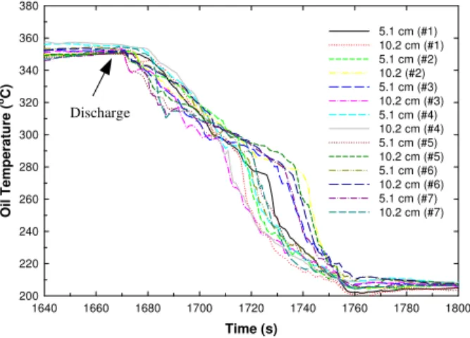
Time (s) 1640 1660 1680 1700 1720 1740 1760 1780 1800 Oil T emperature ( oC) 200 220 240 260 280 300 320 340 360 380 5.1 cm (#1) 10.2 cm (#1) 5.1 cm (#2) 10.2 (#2) 5.1 cm (#3) 10.2 cm (#3) 5.1 cm (#4) 10.2 cm (#4) 5.1 cm (#5) 10.2 cm (#5) 5.1 cm (#6) 10.2 cm (#6) 5.1 cm (#7) 10.2 cm (#7)
Figure 11. Oil temperatures measured at different locations of the oil pan with time
During fire suppression, the MistShield water mist system also effectively cooled hot oil and prevented re-ignition. Average oil cooling rates, which was defined as the ratio of temperature difference between oil ignition temperature and cooled oil
temperature at the end of the water mist discharge to the duration of the water mist discharge, ranged 86.6oC/min to
109oC/min, depending on the water mist discharge pressure, or the amount of water discharged onto the oil. Figure 11 shows the variation of oil temperatures with the time involving Mock-up #3 in Test 2-7. The average oil temperature was cooled down to 200oC from its burning temperature during approximately 89 s of the water mist discharges under a discharge pressure of 689 kPa. Since the cooking oil was effectively cooled down, no re-ignition was observed in the experiments.
Discharge
SUMMARY
A low pressure water mist system, named MistShield, has been developed for industrial oil cooker protection. Its spray and extinguishing performances against large oil fires involving different sizes of the oil cookers were evaluated in the full-scale experiments. The system effectively extinguished large cooking oil fires in 4 to 11 s and cooled hot oil below to 200oC from its burning temperature in less than 90 s of discharge. The extinguishing performance of water mist was further improved with an increase in discharge pressure and the hood in the “down” position. No re-ignition occurred in the oil pan. Water mist discharge did not cause excessive fire flare-up or splash burning oil on non-burning oil outside the cooker. The system has successfully passed through fire test protocols required for industrial oil cooker protection.
ACKNOWLEDGEMENTS
The authors would like to thank Drs. Soonil Nam, Hong-Zeng Yu, Mr. L. B. King of FM Global for their technical assistance to the projects.
REFERENCES
1 Factual Mutual Research Corporation, “Draft Performance Requirements for Water Mist Systems for the Protection of Industrial Oil Cookers,” May 2003. 2 Soonil Nam “Application of Water Sprays to Industrial Oil Cooker Fire,” 7th
International Symposium on Fire Safety Science, Massachusetts, USA, June 2002.
3 Liu, Z.G.; Kim, A.K.; Carpenter, D.W. "Extinguishment of large cooking oil pool fires by the use of water mist systems," 2004 Combustion Institute/Canadian Section Spring Technical Meeting, Kingston, Ontario, May 09, 2004.
4 Liu, Z.G.; Kim, A.K.; Carpenter, D.W. “Application of water mist to extinguish large cooking oil pools for industrial oil cooker protection,” 8th International Symposium on Fire Safety Science, Beijing, China, September 2005.
5 Przybylski, R., “Canola Oil: Physical and Chemical Properties,” Canola Council of Canada Publication, www.canola-council.org, 1999.


![Table 1. Physical Property of Canola Oil [2, 5]](https://thumb-eu.123doks.com/thumbv2/123doknet/14182136.476474/9.918.127.802.816.1078/table-physical-property-canola-oil.webp)