Publisher’s version / Version de l'éditeur:
Heat Transfer Engineering, 33, 1, pp. 4-11, 2012
READ THESE TERMS AND CONDITIONS CAREFULLY BEFORE USING THIS WEBSITE.
https://nrc-publications.canada.ca/eng/copyright
Vous avez des questions? Nous pouvons vous aider. Pour communiquer directement avec un auteur, consultez la
première page de la revue dans laquelle son article a été publié afin de trouver ses coordonnées. Si vous n’arrivez pas à les repérer, communiquez avec nous à [email protected].
Questions? Contact the NRC Publications Archive team at
[email protected]. If you wish to email the authors directly, please see the first page of the publication for their contact information.
NRC Publications Archive
Archives des publications du CNRC
This publication could be one of several versions: author’s original, accepted manuscript or the publisher’s version. / La version de cette publication peut être l’une des suivantes : la version prépublication de l’auteur, la version acceptée du manuscrit ou la version de l’éditeur.
For the publisher’s version, please access the DOI link below./ Pour consulter la version de l’éditeur, utilisez le lien DOI ci-dessous.
https://doi.org/10.1080/01457632.2011.584807
Access and use of this website and the material on it are subject to the Terms and Conditions set forth at
A simple effective viscosity formulation for turbulent flow and heat
transfer in compact heat exchangers
Beale, S. B.
https://publications-cnrc.canada.ca/fra/droits
L’accès à ce site Web et l’utilisation de son contenu sont assujettis aux conditions présentées dans le site LISEZ CES CONDITIONS ATTENTIVEMENT AVANT D’UTILISER CE SITE WEB.
NRC Publications Record / Notice d'Archives des publications de CNRC:
https://nrc-publications.canada.ca/eng/view/object/?id=999a2a3a-850e-47da-92a8-c69a58c6a527 https://publications-cnrc.canada.ca/fra/voir/objet/?id=999a2a3a-850e-47da-92a8-c69a58c6a527Seventh International Conference on Enhanced, Compact and Ultra-Compact Heat Exchangers: From Microscale Phenomena to Industrial Applications
Copyright © 2009 NRC Canada
CHE2009 – xxxx
A SIMPLE EFFECTIVE VISCOSITY FORMULATION FOR TURBULENT FLOW AND
HEAT TRANSFER IN COMPACT HEAT EXCHANGERS
S.B. Beale
National Research Council, Montreal Road, Ottawa, Ontario K1A 0R6, Canada; [email protected]
ABSTRACT
A simple algebraic methodology for computing turbulent stresses and fluxes in arrays of heat exchanger elements is proposed. An effective Reynolds number is computed from the back-projection of the friction or heat transfer factor onto the low-Reynolds number profile. This is then used to obtain the turbulent viscosity for fluid friction, or turbulent Prandtl number for heat transfer. It is shown that under certain circumstances, the resulting mathematical expression is consistent with the Brinkman-Forchheimer modified form of Darcy’s law and also with Reynolds’ quadratic form for frictional/heat transfer resistance. The model is critically appraised in comparison to empirical data for compact and tube bank heat exchangers. The circumstances where it renders a good predictive measure are highlighted and discussed critically.
NOMENCLATURE
b Forchheimer constant, m-1
''
F equivalent shear stress, N/m2
'''
F force per unit volume, N/m3
cp specific heat, W/K D diameter, m Dh hydraulic diameter, m F distributed resistance, kg/(m2s) F0 laminar resistance, kg/(m2s) FT turbulent resistance, kg/(m3) f friction coefficient,
j heat transfer factor
k thermal conductivity, W/(m2K)
L mixing length, m
p pressure, Pa
q''' rate of heat transfer per unit volume, W/m3
r volume/area fraction, porosity
s pitch, m T temperature, K u velocity, m/s U superficial velocity, m/s Greek letters thermal resistance, W/(m3s) permeability, m-2 density, kg/m3 Brinkman constant, kg/(ms) dynamic viscosity, kg/(ms) INTRODUCTION
Computational fluid dynamics (CFD) has, on occasion, been used to generate numerical data on the performance of heat exchangers. Patankar and Spalding (1974) proposed an original methodology for obtaining pressure-drop and heat transfer calculations for engineering-scale heat exchange devices. A porous media analogy was employed. Only the gross motion of the fluid was considered; detailed flow within the individual passages being modelled on a sub-scale of the computational grid. The approach was subsequently adopted by a number of researchers, (for example; Rhodes and Carlucci 1983; Theodossiou and Sousa 1988; Prithiviraj and Andrews 1998a,b; Coelho 1999a,b; Beale and Zhubrin 2005; Gómez et al. 2007). The methodology is particularly appropriate for calculations involving large-scale industrial processes which include heat exchangers as sub-components.
A typical distributed resistance analogy approach involves solution to equations for which a balance of forces on the fluid may be written in the following form, for incompressible flow,
2
div div ' '
grad div grad
r r r t r p Fr r u uu u u u u (1) The quantity 1 2 h F f u rD (2)
is known as a distributed resistance, and u is the mean interstitial velocity. The viscous term on the right-side
2
of Eq. (1), was not considered in the original article by Patankar and Spalding’s (1974). It is a measure of ‘spreading’ or re-distribution of momentum in the heat exchanger passages. Assuming the Boussinesq assumption u u' ' Tgradu , and defining an ‘effective’ viscosity eff T, one may equivalently select either interstitial velocity, u, or superficial velocity, Uru , as state-variable, so that, for constant volume fraction, r,
div grad
div effgrad
p t Fr u uu u u (3) 2 1 div grad
div eff grad
p r t r F r U UU U U (4)
Both forms are found in the literature. Other forms, similar to Eq. (4) but excluding the volume fractions are also employed in certain commercial CFD codes (see for example, Schwarz and Beale 2009). These are however only strictly correct in the two limits of very large and very small F-values (ie. purely Darcy’s and Navier-Stokes’ laws, respectively).
The distributed analogy for heat transfer may be written,
div div grad p P eff rc T rc T t r T T rk T u (5) where 1 2St rDh u (6)A Pr-independent heat transfer factor, j, is defined as jPr1mSt, wherem1 3 is often selected, for lack
of problem-specific data.
Some authors have performed calculations for turbulent heat exchanger flow using models such as the
k- and other methods. However few heat exchangers operate in the high Reynolds-number turbulent regime, and indeed for most geometries, the fluid layer near the solid elements is laminar. The book by Kays and London (1984) contains correlations for friction and heat transfer factors, f and j, for many heat exchanger types. Plotted on a log-log scale, these often exhibit a ‘hockey-stick’ profile starting from an initial negative straight-line of slope near unity, for low Reynolds
number laminar flow, to a flat-horizontal, sic, ‘turbulent’ profile, with a smooth transition in the absence of a clearly-identified critical Reynolds number. A simple physical explanation for this situation is that, with increased mixing, the effective viscosity is greater than the molecular viscosity, thereby reducing the effective Reynolds number.
It was Reynolds (1875) who first suggested that turbulence may be quantified in terms of a quadratic term for the resistance to fluid and heat flow, namely
2 0 T '''F U F U F (7) 2 0 T q''' U U (8)
Following a suggestion by Spalding (2007), based on dimensional considerations, it is proposed here to set,
T L cDh
u u (9)
The non-dimensional constant, c, is the ratio of the mixing-length, L, to hydraulic diameter, Dh. ie a
measure of the length-scale of the mixing relative to the physical geometry. It is common in the literature, to correlate the low Reynolds-number laminar friction coefficient in the form,
0 Rem
f a (10)
For m = 1, 1
2
0 2 h
F a , i.e. FD 0 is
independent of u (but not otherwise if m ). At 1 higher Reynolds numbers, the effect of mixing is to reduce the effective Reynolds number so that,
eff
Rem 1 Re m
f a a c (11)
where Reeff Dh u eff . Equation (11) generates the quadratic form of Eq. (7) with 1
2
0 2 h
F ac for D
the case m = 1 . Equation (11) may thus be conveniently correlated to experimental data, to obtain values of a, m, and c for any given geometry.
3
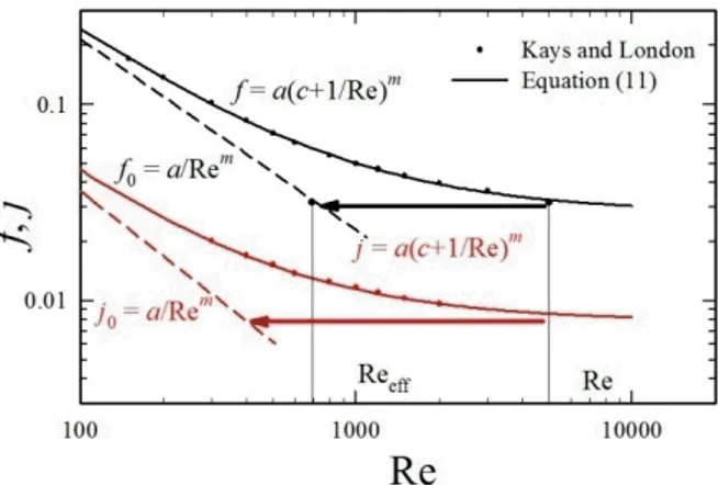
Figure 1. Friction and heat transfer factor for an offset plate-fin surface, showing the basic methodology
RESULTS
Figure 1 shows a correlation of Eq. (11) with smoothed experimental data for an offset-fin strip-fin heat exchanger, namely surface no. 1/9-24.12, core 105 (from Shah and London 1967; Kays and London 1984). It can be seen that Eq. (11), provides an excellent fit to the empirical friction and heat-transfer factor data. The laminar or low Reynolds number factors, f0and j0, are
shown as a straight lines in the figure.
In the ‘turbulent’ regime, the effective viscosity is obtained, e.g. for the case Re = 5 000 shown in Fig. 1, as the back-projection to the laminar f0 characteristic
(with the resulting Reeff= 690 for the case shown) using
eff 1 cRe
(12)
where Reeff Re . This provides the heat eff exchanger engineer with a simple means to calculate eff, obviating the need for ‘two-equation’ procedures.
Inspection of Fig. 1 reveals that a similar treatment may also be successfully applied to heat transfer calculations for the enumeration of the turbulent conductivity or turbulent Prandtl number. For many heat exchangers, empirical correlations of the form, NuaRe Prm n are often provided, with values of m
and n given over a range of Reynolds numbers. Thus
Re, Pr
j j is properly expressed in terms of the Péclet number, j j
Pe , and Eq. (12) may be re-written as keff k 1 cPe. If n is constant (or reasonably so), the Péclet number may be replaced by Reynolds number as independent variable for heat transfer correlations. Although this practice is commonplace in empirical correlations and is also adopted here, it generates slight confusion in the formof two different effective Reynolds numbers for momentum and energy1 (as opposed to employing a
Péclet number as dependent variable in the latter). The reader will note that for the case shown in Fig. 1, the ratio keff k is approximately double that of eff , i.e., i.e., the effect of free stream turbulence upon heat transfer is apparently more pronounced than on momentum transfer.
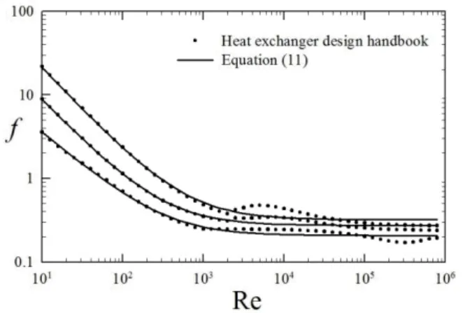
Figures 2 to 7 show further examples of correlations of Eq. (11) with various smoothed-experimental data. Figure 2 shows both f and j correlations with data for louvred plate-fin surface surface no. 3/8 6.006 (from Kays and London 1984). Figure 3 is a similar comparison for plain plate-fin surface, no. 4.00 (again from Kays and London 1984). Figures 4 and 5 show data for friction coefficient, f, for inline square and equilateral triangle tube banks. These are fitted to the empirical correlations of Žukauskas and Ulinskas (2008). The latter are conveniently expressed in the form of power series in Reynolds number, and methods for calculating f for square and non-equilateral geometries are also provided in the article.
Figures. 6 and 7 are correlations of the heat transfer factor, j, for inline and staggered tube bank geometries compared with three correlations; Žukauskas and Ulinskas (1988), ESDU (1973) and Gnielinski (1979) (see also Žukauskas et al. 2008).
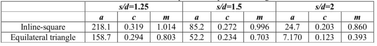
Tables 1 and 2 show values of a, c, and m, obtained for the tube bank fluid flow and heat transfer regression analyses, respectively. The reader will note, that these values were obtained by minimizing the least-squares residual of the function ln f , rather than of f, in order to remove low Re bias in these data, which span numerous decades of values for f and j, as can be seen in Figs. 4–7.
Figure 2. Friction and heat transfer factor for a louvred
plate-fin surface. Figure 3. Friction and heat transfer factor for a plain plate-fin surface.
Figure 4. Friction factor for inline square tube banks,
s/d = 1.25–2.00.
Figure 5. Friction factor for staggered tube banks,
s/d = 1.25–2.00.
Table 1. F-coefficients for inline-square and equilateral triangle tube banks.
s/d=1.25 s/d=1.5 s/d=2
a c m a c m a c m
Inline-square 218.1 0.319 1.014 85.2 0.272 0.996 24.7 0.203 0.860
Equilateral triangle 158.7 0.294 0.803 52.2 0.234 0.703 7.170 0.123 0.393 Table 2. -coefficients for inline and staggered tube banks.
a c m
Inline 0.552 0.0015 0.475 Staggered 0.705 0.0015 0.498
DISCUSSION
For the offset geometry shown in Fig. 1, values of the coefficients for fluid flow/heat transfer were as follows,
a = 19.14/5.72, m= 0.974/1.09, c = 1.24×10⁻³/2.5221×10-3.
A straight-line laminar-zone f0 and j0 region is readily
apparent from the figure. For the louvred geometry of Fig. 2, the present approach agrees well with the smoothed experimental data. For both these cases values of m 1 are observed. At higher Reynolds numbers, as Re ∞, f acm
and the curve approaches a horizontal line. These features are quite typical of porous-media flows, discussed further below.
Figure 3 shows an example of a compact surface where it can be seen that there is a ‘crisis’ or ‘defect’ region above Re = 3 000 marking transition to turbulence. The inline-square tube-bank friction data of Fig. 4 also display a similar defect (though the staggered geometry, Fig. 5 and heat transfer profiles, Figs. 6 and 7, do not). Under these circumstances there are multiple extrema in the profiles, and Eq. (11), can at best only roughly approximate the data, especially at intermediate Reynolds numbers. For the plain-fin geometry, although a straight-line laminar f0 line is
readily apparent for Re ≤ 2 000, the best fit of Eq. (11) over the entire Re range does not necessarily correspond to the best fit (slope) to the laminar line.
For compact inline tube banks, Fig. 4 and Table 1,
m 1, but for widely-spaced inline tube banks m is substantially less than unity, a trend which is even more apparent for the for the equilateral triangle geometry of Fig. 5. Inspection of Table 1, shows that values of m used to approximate the friction coefficient f, differ decrease as the pitch-to-diameter ration increases from m= 0.803 for
s/d = 1.25 to m= 0.393 for s/d = 2.
The tube-bank heat transfer data of Figs. 6 and 7 are charaterised by (i) values of m 0.5 i.e., much less than unity and (ii) by very small values of the constant c. The constant, c, is a measure of relative change in j at higher Reynolds numbers. thus small c-values implies little change,
eff
Pr Pr , in other words ‘turbulence’ has little influence 1 upon heat transfer for these tube banks. whereas the pressure losses are substantially affected and c is correspondingly much larger. The reader will note that both fluid flow and
heat transfer data are derived from a very large number of different experiments, (see Beale 1993, for a discussion of this). In particular, the heat transfer data are for a wide variety of different geometries (equilateral triangle, rotated square, etc.) pitch-to-diameter ratios, and themal boundary conditions (Neumann, Dirichlet, etc). These have been correlated by the authors, as single data sets for all inline and all staggered configurations. Thus the ‘straight-line’ correlations may be, at least partially, an artifact due to data-averaging. It might be better to correlate data for individual geometry/boundary condition combinations.
Porous Media Analogy
For isotropic porous media, the Brinkman-Forchheimer modified form of Darcy’s law (Vafai and Tien 1981) is typically written in terms of superficial velocity;
gradp b div grad
U U U U
0 (13)
where is permeability, b is Forchheimer’s constant, and is Brinkman’s term. In texts on porous media flow (Scheidegger 1974), b and are introduced to account for ‘inertial’ and ‘boundary-layer’ effects respectively. The transient and convective terms are considered negligible, and hence excluded from Eq. (13), provided the permeability, , is sufficiently small. NB: High permeability porous matrices are sometimes used to induce mixing in the passages of heat and mass exchange devices, and under these circumstances the left-hand-side of Eq. (13) is not zero. The correspondence with Eq. (4) is clear and obvious for the case m = 1, namely F0 , FT and b
eff r
. For this case, the f vs. Re curve may be ‘compressed’ onto a single characteristic (Ahmed and Sunada 1969).
For compact surfaces, such as those shown in Figs. 1–3 and also compact inline tube banks m 1, and the ‘permeability’ is thus constant in the laminar region. However the porous media analogy is this is certainly not true in the literal sense for widely-spaced inline- and all equilataral triangle tube banks, where the permeability must
6
6
be considered to be a function of velocity, even at very low Reynolds number. Of course the porous media (distributed resistance) analogy can still be employed in these circumstances, provided the non-linearities are accounted-for.
In texts on porous media, the inertial (Forchheimer) and viscous (Brinkman) terms are generally treated as being independent. In particular there is some controversy about how to enumerate the latter, and whether it is even significant. From the analysis here, it would appear they are related. In other words, the Forchheimer (drag) term arises naturally, as a direct result of the Brinkman (diffusion) term: the increase in drag and heat transfer being associated with increased effective diffusion coefficient.
In heat exchanger texts, the concept of ‘equivalent shear stress’ is sometimes introduced (Kays and London 1984). This is essentially the area analogue of the volumetric body force, viz, F''D '''hF , in Eq. (7). The notion of ‘equivalent shear stress’ thus makes no real distinction between shear and normal stresses, nor for that matter whether these arise due to the action of mean or fluctuating forces. In any event shear forces would tend to increase both Forchheimer and Brinkman terms, whereas normal forces would only increase latter. Thus it may well be that there are difference between the Forchheimer and Brinkman terms, but the model in its presnt form cannot account for these. Moreover, in addition to these kinetic (dynamic) aspects, there may be purely geometric constraints which also influence the shear forces. The matter is further dicussed below.
In favour of the simple model presented here, it must be said that, on the other hand, in computational fluid mechanics and heat transfer, local and overall f vs. Re and j vs. Re correlations are the ‘gold standard’ by which turbulence models (and hence enumeration ofTand kT) are
judged as suitable for a given class of problem, ie. the inertial term is used to ‘calibrate’ the increase in shear due to turbulence. Thus for a first analysis, at least, the selection of a single value of T, both in the viscous and resistance
terms appears quite reasonable. If a single value of Tor kT
cannot effect this, then this is a reflection that a higher-order closure scheme must be found for the problem. Also part of the problem in resolving the Brinkman and Forechheimer terms may also be due to the tacit assumption in standard porous media theory that m = 1 in the laminar zone.
Further Comments
The simple algebraic formula for turbulent viscosity and diffusivity, Eqs. (10) and (11), yields excellent results for both f and j for the compact heat exchanger geometry of Fig. 1. The present author previously conducted detailed laminar CFD calculations (Beale 1990; 1993; 2007) for the same geometry and flow conditions as shown in Fig. 1. Those calculations exhibited a straight-line profile similar to
f0and j0, agreeing with the experimental f and j data at low
Re, but under-predicting as Re increases. Similar observations were also observed for tube bank geometries
(Beale and Spalding 1998). These previous CFD calculations provide some partial empirical evidence in support of the proposed rationale, and for the need to increase the effective viscosity/conductivity at higher Re. In addition to the present results, the book by Kays and London (1984) contained numerous other heat exchanger surfaces which exhibit similar profiles and are equally amenable to the simple regression procedure above. There are, however, numerous configurations for which the f vs. Re characteristic do not conveniently follow the simple form, Eq. (11), such as the cases shown in Figs. 3–5.
Under those circumstances, the definition of the turbulent viscosity (and conductivity) may be modified to admit higher order terms, such as cubic term in Eq. (7), ie.,
Re 1 Re
mf a d c , and so forth. However it can be shown that cubic and quartic forms offer only limited improvement over Eq. (11), ie substantially higher-order polynomical or transcendental functions (Žukauskas, Skrinska et al. 2008) are required to obtain a very good fit to
f and j curves of the form shown in, e.g., Figs. 3–5
Under such circumstance provided f and f0 are
well-defined, eff may still be obtained using the technique
described in this paper as follows. For example, if f0may is
correlated in the form f0a Rem, the task is particularly
simple, and it is straightforward to show.
1 eff Re f m a (14)
Thus regardless of the form of the turbulent drag correlation, if a straight-line laminar region is defined, then Eq. (14) provides a means by which an estimate of the effective viscosity may be made. The same reasoning may be applied to the eddy diffusivity in the energy equation.
The cause of mixing in a heat exchanger does not need to be due to ‘turbulence’ in the commonly-perceived sense (though it could be). The ' 'u u and ' 'uT terms may be considered to arise because of volume averaging in the steady-laminar regime and/or and time averaging in the unsteady-laminar and truly turbulent regimes. For the former case these are then simply to be considered the volume-averaged products of the difference between local values u, v and average-interstitial values. At intermediate Reynolds numbers, it is well-known that there will be increased mixing due to macroscopic phenomena, rather loosely referred to as ‘free-stream turbulence’, and generally associated with vortex shedding, and shear-layer and wake instabilities in the flow, depending on the geometry.
The assumption here is that the fluctuations are isotropic so that the same eff may be found from the
distributed resistance (Forchheimer) term as occurs in the viscous (Brinkman) term, ie., that the eddy viscosity/diffusivity which results in augmenting the drag coefficient, f, also effects ‘mixing’ between the passages of a heat exchanger, as was discussed above. Whether a single scalar effective viscosity can account for diffusion and
7
7
inertial effect can only be ascertained by detailed experiments and/or by direct numerical simulation, whereby both the drag and the diffusion-rate of an obstacle-filled mixing-layer can be obtained. Such data are not available at the time-of-writing of the present work. Of course the diffusion terms may turn out to be negligibly small, for the case shown with c = 1.2410-3, at Re = 10 000,
eff/ = 13.4,
ie the length scale is approximately 13 hydraulic diameters. If a single value of Tor kTcannot effect this, then this
is a reflection of the anisotropy of the problem. The anisotropy may be due to kinetic (fluid motion) or purely geometric factors. Butterworth (1977) argued that F0should
be represented by a second-order tensor, an approach that has been adopted in various forms by others. This would seem to be a reasonable proposition if the heat exchanger elements are aligned in a rectilinear fashion, though less obvious e.g., for equilateral triangle and other non-rectilinear patterns, where the ‘principal directions’ are not orthonomal. Further corollaries would be to consider
FTeffand keffall as tensorial quantities. Clearly this would
add substantial complexity to the problem.
If however, the cause of the anisotropy is actually geometric, in other words whether or not the different fluid streams can ‘see’ each other as it were; an alternative approach might be to consider the geometric volume fractions to be directional: Equation (1) presumes r to be independent of the choice of volume, a corollary of the so-called ergodic hypothesis. Considering, say, a tube-bank heat exchanger with different pitch-to-diameter ratio in the tranverse and longitudinal directions, the area fractions, rx
and rydo not equal the volume fraction r. It would therefore
appear reasonable to re-write the viscous term in Eq. (1), as
say,
2 2 2 2 2 2
eff rx x ry y rz z
u u u . This then would have the desired effect of cutting-off diffusion between ‘unmixed’ fluid streams for example when ry0 but rx . However, the area fractions are themselves open 0 to interpretation in complex geometries, for example as shape or view-factors, ‘seen’ by the components of the flow, or as minimum, or mean aperture values etc. For many widely spaced geometries, the premiss rx= ry= r would still
appear to be a reasonable engineering assumption.
Whether to treat hydraulic resistance or volume fraction, r, as a tensorial quantity is somewhat subjective; the former may be the effect of the shape of the solid elements on the forces acting upon the fluid, whereas the latter is to be considered purely geometric. It is important to appreciate that there are fundamental differences between ordered arrays such as heat exchangers and random porous structures, and that different closure equations (Nakayama 2008) may be appropriate. The goal of this work is not to conduct an exhaustive study of possible closures but rather to propose a simple physical flow model, and to investigate the circumstances under which it is a good model. The situation is more complex still for heat transfer due to the additional heat conduction is also present within the solid matrix, as well as molecular and gross motion of the fluid. In order to further explore the merits of the proposed
algebraic methodology, detailed further detailed experimental data in addition to addition to direct numerical simulation studies are required over a range of geometries and Reynolds numbers.
CONCLUSIONS
An algebraic methodology is proposed for computing the turbulent viscosity and Prandtl number (thermal conductivity) in heat exchangers, based on a value which approximates the value of f or j for any given geometry. The methodology does not resolve the fluctuations within individual passages of a heat exchanger, but rather the overall spatially-averaged behaviour. It is thus suitable for application to CFD simulations in cluttered spaces in industrial equipment, where detailed meshing is not possible. The method assumes that both f0 and j0 may be
correlated in the form f0a Remin the laminar regime, at
low Reynolds numbers. The effective viscosity or conductivity is thus obtained from the back projection onto the laminar distribution. The method may readily be used, provided a well-defined laminar region is identified. A simple expression based on dimensional analyses is shown to generate good correlation with experimental results for compact heat exchanger geometry.
ACKNOWLEDGMENTS
The author would like to thank Prof. D.B. Spalding and Prof. S.V. Patankar who provided useful input and dialogue on the subject matter for this paper, and on many related matters.
REFERENCES
Ahmed, N. and Sunada, D. K., 1969, Journal of the
Hydraulics Division Proceedings ASCE, Vol. 95(HY6), pp.
1947.
Beale, S. B., 1990, Laminar Fully Developed Flow and Heat Transfer in an Offset Rectangular Plate-fin Surface,
PHOENICS J. Comp. Fluid Dynamics, Vol. 3(1), pp. 1-19.
Beale, S. B., 1993, Fluid Flow and Heat Transfer in Tube Banks, PhD thesis, Dept. of Chemical Engineering and Chemical Technology, Imperial College of Science, Technology and Medicine, London.
Beale, S. B., 2007, Use of Streamwise Periodic Conditions for Problems in Heat and Mass Transfer, ASME
J. Heat Transfer, Vol. 129, pp. 601-605.
Beale, S. B. and Spalding, D. B., 1998, Numerical Study of Fluid Flow and Heat Transfer in Tube Banks with Stream-wise Periodic Boundary Conditions, Trans. CSME, Vol. 22(4A), pp. 394-416.
Beale, S. B. and Zhubrin, S. V., 2005, A distributed resistance analogy for solid oxide fuel cells, Numer. Heat
Transfer B, Vol. 47(6), pp. 573-591.
Butterworth, D., 1977, The Development of a Model for Three-dimensional Flow in Tube Bundles, Int. J. Heat
8
8
Coelho, P. J., 1999a, Mathematical modeling of the convection chamber of a utility boiler - an application,
Numer. Heat Transfer A, Vol. 36, pp. 411-428.
Coelho, P. J., 1999b, Mathematical modeling of the convection chamber of a utility boiler - the theory, Numer.
Heat Transfer A, Vol. 36, pp. 429-447.
ESDU, 1973, Convective heat transfer during crossflow of fluids over plain tube banks., Engineering Sciences Data Unit, London.
Gnielinski, V., 1979, Equations for Calculating Heat Transfer in Single Tube Rows and Banks of Tubes in Transverse Flow, International Chemical Engineering, Vol. 19(3), pp. 380-390.
Gómez, A., Fueyo, N. and Diez, L. I., 2007, Modelling and Simulation of Fluid Flow and Heat Transfer in the Convective Zone of a Power-generation Boiler, Applied
Thermal Engineering, Vol. 28(5-6), pp. 532-546.
Kays, W. M. and London, A. L., 1984, Compact Heat
Exchangers, 3rd ed., McGraw-Hill, New York.
Nakayama, A., 2008, Theory of Porous Media and its
Application to Engineering Problems. ICHMT International
Symosium on Advances in Computational Heat Transfer, Marrakech, Morocco, Begell House.
Patankar, S. V. and Spalding, D. B., 1974, A Calculation Procedure for the Transient and Steady-state Behavior of Shell-and-tube Heat Exchangers, in Heat
Exchangers: Design and Theory Sourcebook, N. Afgan and
E. U. Schlünder Eds. Washington. D.C., Scripta Book Company, pp. 155-176.
Prithiviraj, M. and Andrews, M. J., 1998a, Three Dimensional Numerical Simulation of Shell-and-tube Heat Exchangers: Part I: Foundation and Fluid Mechanics,
Numer. Heat Transfer A, Vol. 33(8), pp. 799-816.
Prithiviraj, M. and Andrews, M. J., 1998b, Three Dimensional Numerical Simulation of Shell-and-tube Heat Exchangers: Part II: Heat Transfer, Numer. Heat Transfer A, Vol. 33(8), pp. 817-828.
Reynolds, O., 1875, On the Extent and Action of the Heating Surface of Steam Boilers, Proceedings of the
Literary and Philosophical Society of Manchester, Vol. 14,
pp. 81-85.
Rhodes, D. B. and Carlucci, L. N., 1983, Predicted and
measured velocity distributions in a model heat exchanger.
Paper presented at the 1983 CNS/ANS international conference on numerical methods in nuclear engineering, Montreal.
Scheidegger, A., 1974, The physics of flow through
porous media, 3rd ed., University of Toronto, Toronto and
Buffalo.
Schwarz, D. H. and Beale, S. B., 2009, Calculations of transport phenomena and reaction distribution in a polymer electrolyte membrane fuel cell, Int. J. Heat Mass Transfer.
Shah, R. K. and London, A. L., 1967, Offset Rectangular Plate-fin Surfaces - Heat Transfer and Flow Friction Characteristics, Deptarment of Mechanical Engineering, Stanford University.
Spalding, D. B.,2007. Personal communication to S.V. Patankar. S. V. Patankar.
Theodossiou, V. M. and Sousa, A. C. M., 1988, Flow field predictions in a model heat exchanger, Computational
Mechanics, Vol. 3, pp. 419-428.
Vafai, K. and Tien, C. L., 1981, Boundary and Inertia Effects on Flow and Heat Transfer in Porous Media, Int. J.
Heat Mass Transfer, Vol. 24(2), pp. 195-203.
Žukauskas, A. A., Skrinska, A., Žiugžda, J. and Gnielinski, V., 2008, Banks of plain and finned tubes, in
Heat Exchanger Design Handbook, G. F. Hewitt Ed. New
York, Begell House. 2, pp. 2.5.3-1 - 2.5.3-29.
Žukauskas, A. A. and Ulinskas, R. V., 1988, Heat
Transfer in Tube Banks in Crossflow, Hemisphere, New
York.
Žukauskas, A. A. and Ulinskas, R. V., 2008, Banks of plain and finned tubes, in Heat Exchanger Design
Handbook, G. F. Hewitt Ed. New York, Begell House. 2,
![[PDF] Cours Introduction à VB.NET avec exemples | Cours informatique](data:image/gif;base64,R0lGODlhAQABAIAAAP///wAAACH5BAEAAAAALAAAAAABAAEAAAICRAEAOw==)