Design rules for self-assembled block
copolymer patterns using tiled templates
The MIT Faculty has made this article openly available. Please share how this access benefits you. Your story matters.Citation Chang, Jae-Byum, Hong Kyoon Choi, Adam F. Hannon, Alfredo
Alexander-Katz, Caroline A. Ross, and Karl K. Berggren. “Design Rules for Self-Assembled Block Copolymer Patterns Using Tiled Templates.” Nature Communications 5 (February 17, 2014).
As Published http://dx.doi.org/10.1038/ncomms4305
Publisher Nature Publishing Group
Version Author's final manuscript
Citable link http://hdl.handle.net/1721.1/92710
Terms of Use Article is made available in accordance with the publisher's policy and may be subject to US copyright law. Please refer to the publisher's site for terms of use.
Title:
Design Rules for Self-Assembled Block-Copolymer Patterns
Using Tiled-Templates
Jae-Byum Chang1, Hong Kyoon Choi1, Adam F. Hannon1, Alfredo Alexander-Katz1, Caroline A. Ross1*, and Karl K. Berggren2*
Affiliations:
1Department of Materials Science and Engineering, Massachusetts Institute of Technology, 77 Massachusetts Avenues, Cambridge, Massachusetts 02139, USA
2Department of Electrical Engineering and Computer Science, Massachusetts Institute of Technology, 77 Massachusetts Avenues, Cambridge, Massachusetts 02139, USA
Correspondence and requests for materials should be addressed to K.K.B (email: [email protected]) or to C.A.R ([email protected]).
Abstract:
Directed self-assembly of block copolymers has been used for fabricating various nanoscale patterns, ranging from periodic lines to simple bends. However, assemblies of dense bends, junctions, and line segments in a single pattern have not been achieved by using sparse templates, because no systematic template-design methods for achieving such complex patterns existed. To direct a complex pattern by using a sparse template, the template needs to encode the key information contained in the final pattern, without being a simple copy of the pattern. Here we develop a set of topographic template tiles consisting of square lattices of posts with a restricted range of geometric features. The block-copolymer patterns resulting from all tile arrangements
are determined. By combining tiles in different ways, it is possible to predict a relatively simple template that will direct the formation of non-trivial block-copolymer patterns, providing a new template design method for a complex block-copolymer pattern.
Introduction:
The self-assembly of block-copolymer thin films can generate dense nanoscale patterns over large areas1-8. When directed by a sparse topographic or chemical template, the block copolymers self-assemble into long-range ordered patterns with a controlled orientation9-17. These aligned patterns have been used as lithographic masks to fabricate devices including patterned magnetic recording media, flash memory, and nanowire or graphene ribbon transistors18-25. Aperiodic templates are necessary to fabricate patterns consisting of combinations of bends, line segments and junctions using block copolymer directed self-assembly. Stoykovich et al. and Liu and et al. have shown that an array of jogs, bends or T-junctions and an isolated jog can be formed from a self-assembled polystyrene-b-polymethylmethacrylate (PS-b-PMMA) block copolymer with lamellar-morphology on a chemical template14,15. We have shown previously that a polystyrene-b-polydimethylsiloxane (PS-b-PDMS) block copolymer with cylindrical-morphology can be directed to form an array of bends by using a topographic template13. These approaches rely on the intuitive design of templates that contain features with similar density and arrangement to the features in the target pattern and produce relatively simple and periodic patterns. Recently, we theoretically designed templates for directed self-assembly using a Monte Carlo algorithm to move posts randomly within the simulation cell until the free energy is minimized. By using this method, a template for an array of junctions was predicted26,27, but the template features were not constrained to
have any predetermined spacing or location. What is missing in these three approaches is the ability to template patterns over a large area that contain complex assemblies of dense bends, terminations, and junctions directed by a simple (and therefore, more easily manufacturable) template.
In this letter, we present a general and modular approach to designing and fabricating dense and complex block-copolymer patterns by developing block-copolymer assembly rules for square template tiles and joining the tiles together in a mosaic to form various complex block-copolymer patterns. The template tiles consisted of a restricted set of post motifs. By limiting the number of possible post motifs, we study both experimentally and through simulations the block-copolymer patterns and defects generated from all tile combinations as well as interactions between the tiles. Based on these results, we develop a set of template design tiling rules for our system that can be used for designing a template to achieve a complex block-copolymer pattern.
Results:
Development of rules for a square-grid template
We first demonstrate that the orientation of block-copolymer cylinders can be restricted to two orthogonal in-plane directions by using a square lattice of topographic features. Square lattices of topographic single posts with a pitch of 39 nm were fabricated by means of electron-beam lithography. Next, the substrates and posts were chemically functionalized with hydroxyl-terminated PDMS28. A PS-b-PDMS block copolymer with cylindrical-morphology was spin-coated onto the substrate, and then solvent-annealed and finally etched to yield oxidized PDMS cylinders. On an unpatterned substrate, the observed equilibrium periodicity of the PDMS
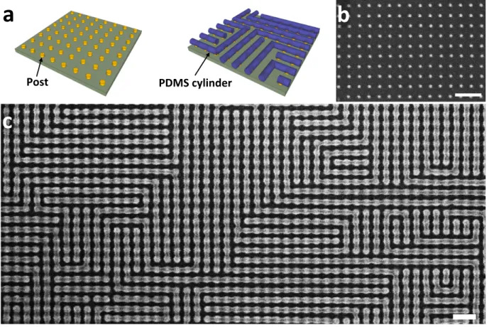
cylinders (L0) was ~39 ± 2 nm. Figure 1 shows PDMS cylinders formed on a substrate with a single-post array which had a periodicity of L0 (39 nm). Figure 1b,c show scanning electron microscopy (SEM) images of the 39-nm-periodicity post array and the PDMS cylinders templated by this post array. As shown in Figure 1c, the block copolymer pattern templated by an array of single posts consisted of many grains (regions of parallel cylinders). The grains were degenerately aligned parallel either to the x-axis or to the y-axis, since both orientations were equally probable and both directions were commensurate orientations. Bends and terminations formed where two grains with different orientations met. The position of the bends or terminations was random, because the size of the grains was not uniform and also the center positions of the grains were not evenly spaced. As the templates occupy only a small fraction of the final pattern, fabricating the square lattice of posts instead of the complete pattern of lines would increase the throughput of the lithography process, provided the positions of the bends and terminations can be controlled.
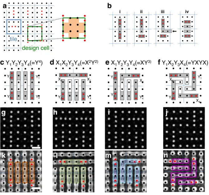
To control the positions of the bends and terminations, we introduced double posts to the square array of single posts. In previous work, double posts were shown to promote block copolymer cylinders to align parallel to the direction of the double posts13. By replacing a single post in the array with a double post, we can locally break the degeneracy of the square array. We replaced one out of every nine single posts with a double post (Figure 2a). We defined the resulting 3×3 post array consisting of eight single posts and one double post at the center as a tile. As a result, a large square array of single and double posts shown in Figure 2a can be regarded as a checkerboard of tiles. However, the post array can be described equivalently by using another cell, defined as a design cell. As shown in Figure 2a and the inset of Figure 2a, a
design cell consists of four single posts at the center and four double posts and eight single posts at the boundary. Because the single and double posts at the boundary are shared with the neighbor design cells, one design cell consists of eight single posts and one double post. Unlike a tile, the block copolymer cylinders formed on the single posts in the design cell (colored region in the inset of Figure 2a) are primarily templated by the four double posts at its boundary. So, the block copolymer pattern of a design cell is primarily determined by the orientations of the surrounding four double posts. The periodicity of the post template defines the periodicity of the final block copolymer pattern, and can be altered slightly (~+/- 10%) from L0 while still effectively templating the block copolymer.
To gain insight into how the PDMS-cylinder pattern on a single post in a design cell varies depending on the orientations of the surrounding four double posts, we first studied PDMS cylinders in between two double posts. As shown in Figure 2b, the PDMS cylinder connected the double posts via the two single posts when the double posts were parallel (Figure 2b-i). The PDMS cylinders made a termination when the two double posts were perpendicular to each other (Figure 2b-ii). However, the PDMS cylinders formed a bend at the single posts instead when another cylinder from a neighboring post (indicated by an arrow in Figure 2b-iii) came into the structure (Figure 2b-iii). When the double posts were aligned parallel to each other in the orthogonal in-plane direction, the PDMS cylinders aligned parallel to the double posts (Figure 2b-iv).
By applying the four general observations mentioned above, we predicted the block-copolymer pattern templated by each design-cell arrangement. Each double post can be
aligned along one of two directions with 16 (24) possible combinations of the orientations of the four double posts in the design cell. The 16 combinations can be grouped into just four arrangements that are not equivalent under 90o rotations or mirror transformations. Figure 2c-f show the four arrangements and the predicted block-copolymer patterns based on the rules described in Figure 2b. We introduced a notation X1X2Y3Y4, in which the 1st, 2nd, 3rd, and 4th letters represent the orientation of the double post in the upper right, upper left, lower left, and lower right quadrant respectively. For a Y1Y2Y3Y4 (=Y4) arrangement (Figure 2c), the light-gray rectangles connecting dark-gray rectangles on the Y1 and Y4 double posts, and the Y2 and Y3 double posts were predicted based on the observation in Figure 2b-i. Light-gray rectangles on the single posts between the Y1 and Y2 double posts, and the Y3 and Y4 double posts were predicted based on Figure 2b-iv. After that, white rectangles on the four single posts at the center of the design cell were predicted to align parallel to the surrounding block-copolymer patterns (dark- and light-gray rectangles). For the other three arrangements, the block-copolymer patterns were predicted based on the observations in Figure 2b-i,ii,iv for an X1X2Y3Y4 (=X2Y2) arrangement (Figure 2d), Figure 2b-i,ii,iii,iv for a X1Y2Y3Y4 (=XY3) arrangement (Figure 2e), and Figure 2b-iii for an Y1X2Y3X4 (=YXYX) arrangement (Figure 2f). In these three arrangements, the patterns on the four single posts at the center of each design cell were predicted to align parallel to the surrounding block-copolymer patterns.
When a block-copolymer film was annealed with these four design-cell arrangements, the PDMS cylinders formed various patterns on each arrangement. Figure 2k-n show SEM images of the most frequently observed patterns formed on the four arrangements. For Y1Y2Y3Y4 (=Y4), X1X2Y3Y4 (=X2Y2), and X1Y2Y3Y4 (=XY3) arrangements, the most frequently observed patterns
were identical to the predicted patterns shown in Figure 2c-e. However, for an Y1X2Y3X4 (=YXYX) arrangement, the predicted pattern in Figure 2f was not observed. Instead, several patterns were observed from the YXYX arrangement (Supplementary Figure 1 and Supplementary Discussion 1), with the one shown in Figure 2n occurring most frequently. In several experimental trials, the pattern of Figure 2n was observed in 20% of the YXYX cells.
Prediction of patterns formed on a given template
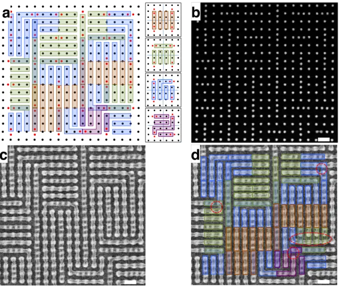
To show that the patterns in Figure 2k-n can be used for predicting the block-copolymer pattern formed on a large-area-template, we fabricated a square array template of single and double posts and checked whether the final PDMS pattern agreed with the predictions. Figure 3a shows the test template layout in which the orientations of the double posts in the layout were random. The design cells having Y4, X2Y2, XY3, and YXYX arrangements were predicted based on the patterns in Figure 2k-n, as shown in Figure 3a. When the predicted patterns from two neighboring design cells conflicted, the pattern was determined by the basic observations shown in Figure 2b (Supplementary Figure 2 and Supplementary Discussion 2). Figure 3b shows a SEM image of the template and Figure 3c shows the PDMS patterns directed by the template of Figure 3b. To quantify the accuracy of the prediction, we introduced the design cell prediction yield
DY%. DY% was defined as the ratio of the number of completely matched design cells to the total number of design cells. To quantify the degree of similarity between the predicted pattern and observed pattern, we introduced the grid prediction yield GY%. GY% was defined as the ratio of the number of matched features on individual grid points to the total number of grid points (Supplementary Figure 3 and Supplementary Discussion 3). When the predicted pattern was compared with the block-copolymer pattern, GY% = 97% (467/480) (more typically GY% ≈ 90%)
and DY% = 76% (19/25), as shown in Figure 3d. Red circles and ellipsoid indicate mismatches between the prediction and experimental result.
Template design to achieve a target pattern
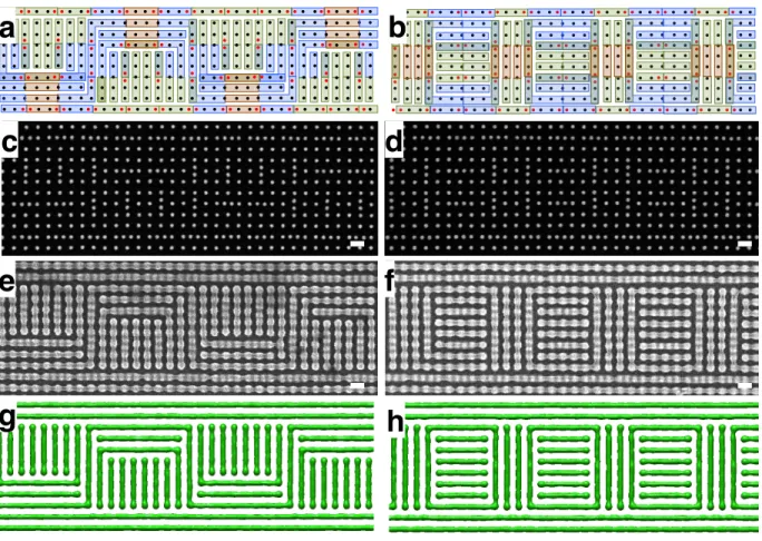
To demonstrate that complex target patterns can be templated by applying appropriate design rules, we fabricated two complex patterns consisting of many bends and terminations. Figure 4a,b show the template layouts and the block copolymer patterns predicted to form on these templates. Figure 4c,d show SEM images of the templates and Figure 4e,f show the PDMS patterns directed by the templates. Here GY% = 97% (Figure 4e) and 99% (Figure 4f). Furthermore, as shown in Figure 4g,h, self-consistent field theory (SCFT) simulations29-33 were used to calculate the block copolymer morphology resulting from the input templates of Figure 4a and 4b. There is a very good agreement between the structure predicted from the empirically-derived design rules, the structure predicted by SCFT, and the structure observed in the experiments. The tile-based approach produces a limited range of microdomain arrangements from the four basic template arrangements, and therefore the large area patterns that can be produced by concatenating them are also limited. We expect that a different set of tiles with a greater number of basic geometries would give access to more diverse patterns. The utility of the tile-based approach comes from a compromise between having a template that can produce enough patterns to concatenate into useful structures, while avoiding a template that produces so many patterns that the selectivity between them is too small for design rules to be applicable.
Free energy of various patterns formed on two arrangements
we fabricated a large template array consisting of various different combinations of tile arrangements and observed the self-assembled patterns of the block copolymer on the template.
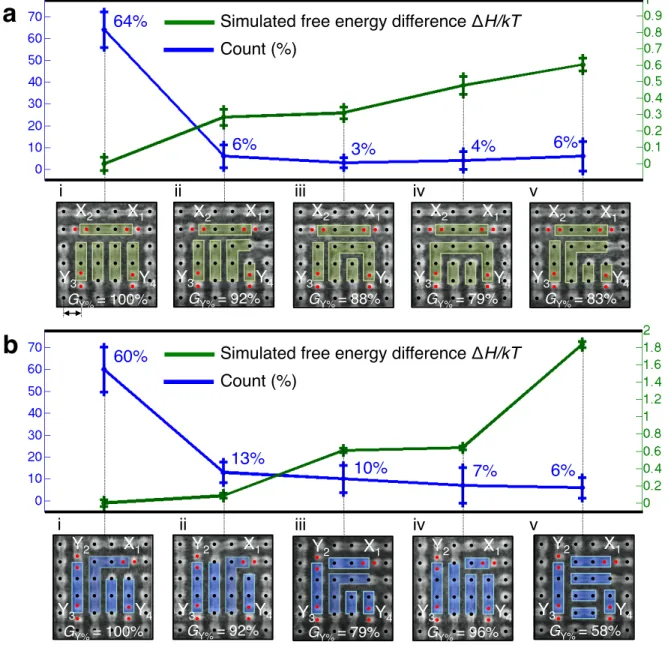
DY% was 100% for the Y4 arrangement having four parallel PDMS cylinders regardless of the arrangement of their nearest neighbor design cells. DY% = 64% for the X2Y2 arrangement having a pattern identical to the predicted pattern, as shown in Figure 5a-i. However, 7% of the X2Y2 arrangements yielded an internal bend, as shown in Figure iii,iv. As shown in Figure 5a-ii,iii,iv,v, GY% of the unmatched patterns were 92%, 88%, 79%, and 83% respectively. For the XY3 arrangement, DY% was 60%, as shown in Figure 5b-i. In 13% of the XY3 arrangements, the position of a bend was shifted by one grid point to the X1 double post, as shown in Figure 5b-ii. In 10% of the XY3 arrangements, the position of a bend was shifted by one grid point to the Y3 double post, as shown in Figure iii. The pattern mismatch in Figure 5a-ii,iii,iv,v and 5b-ii,iii,iv resulted from a common defective feature. We expect that the formation of this defect could be reduced by modifying the cell geometry, e.g. by using an elliptical post (Supplementary Figure 4 and Supplementary Discussion 4).
To gain insight about the relative counts of the patterns shown in Figure 5, we used SCFT simulations to compute the free energy of those patterns and investigate the equilibrium stability of the patterns. These free energy comparisons for the 5 structures seeded for the X2Y2 and XY3 arrangements are shown in Figure 5a and b respectively. The general trend here is that the structures observed with a lower frequency had a higher free energy than the structure found most often. The qualitative agreement is good even though the model does not account for several features of the physical system: in particular, the SCFT model does not consider the solvent anneal explicitly but rather implicitly through an effective 𝜒, and does not consider
kinetic limitations to the formation of structures. It also is limited to periodic boundary conditions, does not consider fluctuations in film thickness, and the parameters for surface affinity, post geometry, etc. are not exact. Although kinetic effects are expected to be relevant, the fact that the less frequently observed structures have higher free energies in the simulation implies that the morphology is primarily driven by thermodynamic considerations, suggesting the model is useful in characterizing the most probable morphologies.
Discussion:
The restricted set of geometric features presented in this study allows one to design a template for fabricating a complex pattern without relying on intuition13. The templating effect of one double post is mainly decided by the orientations of its neighboring double posts, and is therefore restricted to its local surroundings. Predicting a block-copolymer pattern from a given template layout or designing a template layout for a target pattern is therefore simplified to just assembling design cells, and we expect that in principle, non-trivial patterns over a large area (e.g. a pattern relevant to an integrated circuit layout) could be achieved.
This approach to complex templating provides advantages in the context of nanolithography. First, the time required for writing the template using electron-beam lithography can be a factor of 5 or more shorter than the time required to write the complete pattern (Supplementary Figure 5 and Supplementary Discussion 5). The throughput could be further increased by using a two-step process for template generation, instead of writing all the posts serially: (1) the basic square array of posts could be fabricated by interference lithography or another massively parallel technique, which can generate periodic patterns over a large area
with high throughput; and (2) the aperiodic double posts could then be fabricated by electron-beam lithography or by another serial method (Supplementary Figure 5 and Supplementary Discussion 5). Second, we believe that the four block copolymer patterns shown in Figure 2k-n are only a subset of block copolymer patterns that could be achieved. We expect that a variety of block copolymer patterns could be achieved by fine-tuning parameters including the height and diameter of the posts and the block copolymer film thickness, volume fraction and annealing conditions. Additional template arrangements could be developed by removing a post or using a triple post or quadruple post instead of a double post. For example, a T-junction was formed reproducibly when a post was missing (Supplementary Figure 6 and Supplementary Discussion 6). Tiles incorporating such features would extend the rules and the available block copolymer geometries beyond what has been demonstrated here. Third, this approach could be used to achieve a block copolymer pattern with higher resolution. For example, a block copolymer pattern with a periodicity of 18 nm could be achieved by templating a 16 kg/mol PS-b-PDMS block copolymer16 using a square post array with a periodicity of 18 nm and double posts with a post spacing of 12 nm. This resolution is difficult to achieve with electron-beam lithography, but similar resolution has been achieved by helium-ion beam lithography34 and scanning transmission electron microscopy lithography35
In summary, a template design based on a restricted set of tiles with post motifs provides a way to achieve a complex pattern of line segments with bends and terminations from a relatively simple template. Forming a complex block-copolymer pattern by concatenating design cells (tiles) derived from a limited number of local template arrangements greatly reduces the difficulty of the template design process and the amount of experimentation required to achieve
the target pattern. This approach, starting from a degenerate template, adding a restricted set of perturbations, and developing rules for all possible perturbation arrangements, could potentially be applied to other self-assembling systems that can be templated by topographic or chemical features. Rule-based patterning strategies have been developed for other self-assembling systems such as DNA origami36-38. In DNA origami, the information used to control the patterning is input via DNA synthesis, and is thus too slow to address the enormous challenge of pattern generation in a modern technological setting (a single mask for the semiconductor industry can take 5 days to pattern at a data-input rate of 108 bits per second). The application of such rule-based strategies to simple chemical systems, such as block copolymers, potentially solves the modern pattern generation problem, as the information defining the pattern is input lithographically. We expect that rule-based strategies could be developed further to describe assembly of other nanoscale objects such as nanoparticles, for example by functionalizing or programming nanoparticles with ligands that promote specific types of interactions39,40. Extensions of the algorithmic strategies described here for block copolymers may enable further levels of control over the final pattern, and ultimately lead to a robust inverse-design process that determines the optimum template for a given target pattern.
Method:
Template fabrication
The templates were fabricated by using electron-beam patterning of hydrogen silsesquioxane (HSQ). HSQ films (XR-1541 2% solids from Dow Corning) with a thickness of 28 ± 1nm were spin-coated on a silicon substrate. Single-pixel dots were exposed in an Elionix ELS-F125 electron-beam lithography tool at 125 kV acceleration voltage. Square arrays of single dots with
a diameter of 10 ± 1 nm and a range of pitches from 30 to 42 nm were exposed. The exposed samples were developed with a salty development system as described previously41. The developed sample was treated with O2/He plasma (50 W, 10 sec) to convert HSQ posts into silicon oxide. To measure the diameter of the templates, SEM images of the templates were obtained by using a Raith 150 scanning electron microscope operated with an acceleration voltage of 10 kV. The errors of the template diameter were estimated from visual inspection of the SEM images.
Block copolymer self-assembly
The patterned substrates were treated with a hydroxyl-terminated PDMS brush layer (0.8 kg/mol, Polymer Source Inc., 170 °C for 12 h) to render the HSQ nano-posts attractive to the PDMS block. 2% of PS-b-PDMS (Mw = 45.4 kg/mol, fPDMS = 33.5%, Polymer Source Inc.) solution in propylene glycol monomethyl ether acetate (PGMEA) was spin coated onto templated substrate to a thickness of 35 nm. The films were solvent annealed using either a flow-controlled solvent annealing system or conventional solvent annealing system for 3 h. In the flow-controlled solvent annealing system, nitrogen gas was bubbled through a liquid reservoir of a 5:1 mixture of toluene and heptane at a flow rate of 10 sccm and diluted by nitrogen gas flow of 0.7 sccm so that the annealing chamber was maintained at constant solvent vapor pressure. The vapor pressure was controlled by changing the flow ratio between the solvent stream and the nitrogen stream42. In the conventional solvent annealing system, the sample was placed in a chamber containing a reservoir of liquid solvent (5:1 mixture of toluene and heptane). On an unpatterned substrate, the equilibrium periodicity of the PDMS cylinders (L0) was ~39 ± 2 nm.
Reactive ion etching
The annealed block copolymer films were treated with a 50 W, 10 mTorr CF4 plasma for 5 sec and then a 90 W, 6 mTorr O2 plasma for 22 sec to remove the top PDMS surface layer and then the PS matrix. This two-step reactive ion etching process left oxygen-plasma-modified PDMS cylinders on the substrate13. The PDMS cylinders were imaged with a Raith 150 SEM operated with an acceleration voltage of 10 kV.
SCFT simulation
The SCFT simulations used here use the same equations and computational methods as presented in the supporting information of previous work by Mickiewicz et al.31. In the SCFT simulations, the system was modeled by using hard-wall field boundary conditions that represented the topographic posts used in experiment and PDMS attractive potentials that represented the surface-air interface and brush layer. The system was discretized onto an 𝑁!×𝑁!×𝑁! grid with a course-graining of 9 grid points assigned to a distance of L0. Both 2D (𝑁!= 1) and 3D simulations were performed for comparison (note that only the final 3D results are reported here). The posts were modeled with a hard-wall potential field value surrounded by an attractive field parameter modeling the PDMS brush layer. Two coarse grainings of posts were used as schematically shown in Supplementary Figure 7 with the first single point hard-wall potential corresponding to ~8 nm post and brush layer and the second five point hard-hard-wall potential corresponding to ~16 nm post and brush layer. These 9-by-9 grids were concatenated to form the entire simulation cells used with periodic boundary conditions imposed in the planar directions and confined boundary conditions in the thickness direction for the 3D simulations.
The resulting simulation cells were on the order of ~108 by ~108 by 20 grid points (the thickness here chosen to roughly correspond to a swelling thickness observed in experiment of ~2.0 L0). The lateral grid points used varied depending upon the simulations.
Since the primary interest in using the simulations was to explore the energetics of various structures, most simulations were seeded with target structures and the chemical potential fields relaxed holding the seeded density fields constant to obtain estimates of the free energy of the structures. These target-structure density fields were created by first simulating a single cylinder feature over a single or double post in a 9-by-9-by-20 grid and then concatenating the field results into the appropriate seed structure. The field relaxation required two steps. First the exchange field 𝛺! was relaxed until the free energy reached an approximately constant value (~10,000 to 20,000 iterations). Then the pressure fields 𝛺! were relaxed based on the density solution of the relaxed 𝛺! until the free energy was again approximately constant. Various likely seed structures were used to test each template.
In the experiment, the film thickness during solvent swelling varied from around 1.5 to 2.0 L0, so in the simulations a film thickness corresponding to 2.0 L0 was chosen for simplicity in 3D simulations, though further studies on the effect of film thickness on the structures and viability of the design rules for these thicknesses should be taken into consideration. The post heights used in experiment were around ~2/3 L0 but it has been observed that the exact height in relation to the film thickness affects the final morphology, so various post heights were tried in preliminary simulations. Since the experimental system is solvent annealed, the exact equilibrium volume fraction may not be exactly the bulk value due to the solvent preferentially
swelling the two blocks differently. Thus different volume fractions were tried during preliminary simulations. The exact 𝜒 value used was reduced by a factor of ~1/2 since the solvent was modeled implicitly by varying 𝜒 and the volume fraction (assuming ~50% of the system consists of solvent). Since all these parameters need to be optimized for comparison with experiment, an initial screening of the structure made experimentally in Figure 3g was initiated in the simulations for a range of post heights from 0.67 L0 to 1.11 L0 and a range of volume fractions from 0.30 to 0.37 on a 162-by-81-by-16 grid. Here the thickness corresponded to 1.5 L0. The resulting minority densities after 10,000 iterations were calculated and are shown for the interface density of 0.5 in 3D along with the total energy of the system (not normalized by grid point volume) in Supplementary Figure 8. From these simulations, the seeded structure only stabilized for volume fractions greater than 0.35 in the simulation. For all the post heights used, these higher volume fractions kept the structure after relaxing the fields, but the lowest energy structure occurred for the shorter posts. Based on these considerations, the lowest volume fraction that kept the structures intact of 0.36 and height that gave the lowest free energy of 0.78
L0 were chosen to use as the parameters for free energy comparison simulations of structures observed in the X2Y2 and XY3 design cells. These parameters do not correspond exactly to the experiment, so other parameters such as total design cell thickness and surface energy attraction strength could be optimized to get better corresponding results. However, this optimization is not necessary since only general free energy trends were of interest. The surface energy attraction strength was based upon the values used in previous studies4.
Using the parameters corresponding to stable formation of the target cylindrical patterns, the 10 structures shown in Figure 4 were each seeded into a simulation box with appropriate
X2Y2 and XY3 template boundary conditions. To eliminate effects of periodic boundary conditions, internal reflective boundary conditions were implemented such that a 4-fold reflective simulation cell was created for the structures with additional buffer layers of X4 or Y4 design cells that were the same in each simulation for the given boundary conditions. In these simulations, the block copolymer was modeled with a Flory-Huggins parameter 𝜒 = 0.224,
N = 125 effective Kuhn monomer segments and volume fraction of f = 0.36, and topographic
post features modeled as hard wall potential fields surrounded with a preferential surface field to model brush layer surface energies and air-interface surface energies in periodically bound design cells of size 81-by-81-by-20. The density fields that were seeded are shown as 3D isosurface for the 50% interface density between the two blocks in Supplementary Figure 9. The difference in the free energy of the structures calculated holding the density fields constant while relaxing the fields and their standard deviation are thus shown in the main text in Figure 4. Note that the use of reflective boundary conditions rather than considering neighboring design cells as well as having a buffer layer of the Y4 structure may change some of the energetics at the boundary of the structures. Since the connectivity of the cylinders differs only in the design cell of interest across a given post template, one can safely compare the relative free energies of these structures. The absolute values of these energies are not as important since they depend on the boundary conditions used. Ideally one would want to calculate a free energy of an isolated design cell, but because there are always boundary issues at the connections, there are inherently effects due to the neighboring design cells or whatever boundary conditions are chosen that affects the final energetics of the system.
References :
1. Bates, F. S. & Fredrickson G. H. Block copolymer thermodynamics: theory and experiment.
Annu. Rev. Phys. Chem. 41, 525-557 (1990).
2. Park, M., Harrison, C., Chaikin, P. M., Register, R. A. & Adamson D. H. Block copolymer lithography: periodic arrays of 1011 holes in 1 square centimeter. Science 276, 1401-1404 (1997).
3. Darling, S. B. Directing the self-assembly of block copolymers. Prog. Polym. Sci. 32, 1152-1204 (2007).
4. Segalman, R. A. Patterning with block copolymer thin films. Mat. Sci. Eng. R 48, 191-226 (2005).
5. Park, C., Yoon, J. & Thomas E. L. Enabling nanotechnology with self-assembled block copolymer patterns. Polymer 44, 6725-6760 (2003).
6. Tang, C., Lennon, E. M., Fredrickson, G. H., Kramer, E. J. & Hawker, C. J. Evolution of block copolymer lithography to highly ordered square arrays. Science 322, 429–432 (2008). 7. Bang, J., Kim, S. H., Drockenmuller, E., Misner, M. J., Russell, T. P. & Hawker, C. J.
Defect-free nanoporous thin films from ABC triblock copolymers. J. Am. Chem. Soc. 128, 7622– 7629 (2006).
8. Bates, C. M., Seshimo, T., Maher, M. J., Durand, W. J., Cushen, J. D., Dean, L. M., Blachut, G., Ellison, C. J. & Willson, C. G. Polarity-switching top coats enable orientation of sub-10-nm block copolymer domains. Science 338, 775-779 (2012).
9. Kim, S. O., Solak, H. H., Stoykovich, M. P., Ferrier, N. J., de Pablo, J. J. & Nealey, P. F. Epitaxial self-assembly of block copolymers on lithographically defined nanopatterned substrates. Nature 424, 411-414 (2003).
10. Stoykovich, M. P., Muller, M., Kim, S. O., Solak, H. H., Edward, E. W., de Pablo, J. J. & Nealey, P. F. Directed assembly of block copolymer blends into nonregular device-oriented structures. Science 308, 1442-1446 (2005).
11. Ruiz, R., Kang, H., Detcheverry, F. A., Dobisz, E., Kercher, D. S., Albrecht, T. R., de Pablo, J. J. & Nealey, P. F. Density multiplication and improved lithography by directed block copolymer assembly. Science 321, 936-939 (2008).
12. Bita, I., Yang, J. K. W., Jung, Y. S., Ross, C. A., Thomas, E. L. & Berggren, K. K. Graphoepitaxy of self-assembled block copolymers on two-dimensional periodic patterned templates. Science 321, 939-943 (2008).
13. Yang, J. K. W., Jung, Y. S., Chang, J., Mickiewicz, R. A., Alexander-Katz, A., Ross, C. A. & Berggren, K. K. Complex self-assembled patterns using sparse commensurate templates with locally varying motifs. Nat. Nanotechnol. 5, 256-260 (2010).
14. Liu, G., Thomas, C. S., Craig, G. S. W. & Nealey, P. F. Integration of density multiplication in the formation of device-oriented structures by directed assembly of block copolymer-homopolymer blends. Adv. Funct. Mater. 20, 1251-1257 (2010).
15. Stoykovich, M. P., Kang, H., Daoulas, K. Ch., Liu, G., Liu, C., de Pablo, J. J., Muller, M. & Nealey, P. F. Directed self-assembly of block copolymers for nanolithography: fabrication of isolated features and essential integrated circuit geometries. ACS Nano 1, 168-175 (2007).
16. Chang, J., Son, J. G., Hannon, A. F., Alexander-Katz A., Ross, C. A. & Berggren, K. K. Aligned sub-10-nm block copolymer patterns templated by post arrays. ACS Nano 6, 2071-2077 (2012).
17. Park, S., Lee, D. H., Xu, J., Kim, B., Hong, S. W., Jeong, U., Xu, T. & Russell, T. P. Macroscopic 10-Terabit-per-square-inch arrays from block copolymers with lateral order.
Science 323, 1030-1033 (2009).
18. Black, C. T. Self-aligned self-assembly of multi-nanowire silicon field effect transistors.
Appl. Phys. Lett. 87, 163116 (2005).
19. Cheng, J. Y., Jung, W. & Ross, C. A. Magnetic nanostructures from block copolymer lithography: hysteresis, thermal stability, and magnetoresistance. Phys. Rev. B 70, 064417 (2004).
20. Yi, H., Bao, X., Zhang, J., Bencher, C., Chang, L., Chen, X., Tiberio, R., Conway, J., Dai H., Chen, Y., Mitra, S. & Wong, H. -S. P. Flexible control of block copolymer directed self-assembly using small, topographical templates: potential lithography solution for integrated circuit contact hole patterning. Adv. Mater. 24, 3107-3114 (2012).
21. Thurn-Albrecht, T., Schotter, J., Kastle, G. A., Emley, N., Shibauchi, T., Krusin-Elbaum, L., Guarini, K., Black, C. T., Tuominen, M. T. & Russell, T. P. Ultrahigh-density nanowire arrays grown in self-assembled diblock copolymer templates. Science 290, 2126–2129
(2000).
22. Jung, Y. S., Jung, W., Tuller, H. L. & Ross, C. A. Nanowire conductive polymer gas sensor patterned using self-assembled block copolymer lithography. Nano Lett. 8, 37760-3780 (2008).
23. Bai, J., Zhong, X., Jiang, S., Huang, Y. & Duan, X. Graphene nanomesh. Nat. Nanotechnol. 5, 190-194 (2010).
24. Liang, X. & Wi, S. Transport characteristics of Multichannel Transistors made from densely aligned sub-10-nm half-pitch graphene nanoribbons. ACS Nano 6, 9700 – 9710 (2012). 25. Zschech, D., Kim, D. H., Milenin, A. P., Scholz, R., Hillebrand, R., Hawker, C. J., Russell, T.
P., Steinhart, M. & Gosele, U. Ordered arrays of <100>-oriented silicon nanorods by CMOS-compatible block copolymer lithography. Nano Lett. 7, 1516-1520 (2007)
26. Hannon, A. F., Gotrik, K. W., Ross, C. A. & Alexander-Katz, A. Inverse design of topographical templates for directed self-assembly of block copolymers. ACS Macro Lett. 2, 251-255 (2013).
27. Hannon, A. F., Ding, Y., Ross, C. A. & Alexander-Katz, A. Optimizing topographical templates for directed self-assembly of block copolymers via inverse design simulations.
Nano Lett. ASAP (2013).
28. Jung, Y. S. & Ross, C. A. Orientation-controlled self-assembled nanolithography using a polystyrene-polydimethylsiloxane block copolymer. Nano Lett. 7, 2046-2050 (2007). 29. Fredrickson, G. H. The equilibrium theory of inhomogeneous polymers (Oxford University
Press, New York, NY, 2006).
30. Fredrickson, G. H., Ganesan, V. & Drolet, F. Field-theoretic computer simulation methods for polymers and complex fluids. Macromolecules 35, 16-39 (2002).
31. Mickiewicz, R. A., Yang, J. K. W., Hannon, A. F., Jung, Y., Alexander-Katz, A., Berggren, K. K. & Ross, C. A. Enhancing the potential of block copolymer lithography with polymer self-consistent field theory simulations. Macromolecules 43, 8290-8295 (2010).
32. Tavakkoli, A., Gotrik, K. W., Hannon, A. F., Alexander-Katz, A., Ross, C. A. & Berggren, K. K. Templating three-dimensional self-assembled structures in bilayer block copolymer films. Science 336, 1294-1298 (2012).
33. Tavakkoli, A., Hannon, A. F., Gotrik, K. W., Alexander-Katz, A., Ross, C. A. & Berggren, K. K. Rectangular symmetry morphologies in a topographically templated block
copolymer. Adv. Mater. 24, 4249-4254 (2012).
34. Sidorkin, V., Veldhoven, E., Drift, E., Alkemade, P., Salemink, H. & Maas, D. Sub-10-nm nanolithography with a scanning helium beam. J. Vac. Sci. Technol. B. 27, L18-20 (2009) 35. Manfrinato, V., Zhang, L., Su, D., Duan, H., Hobbs, R. G., Stach, E. A. & Berggren, K. K.
Resolution limits of electron-beam lithography toward the atomic scale. Nano Lett. 13, 1555-1558 (2013)
36. Winfree, E. Liu, F., Wenzler, L. A. & Seeman, N. C. Design and self-assembly of two-dimensional DNA crystals. Nature 394, 539 – 544 (1998).
37. Wei, B., Dai, M. & Yin, P. Complex shapes self-assembled from single-stranded DNA tiles.
Nature 485, 623-627 (2012).
38. Rothemund, P. W. K., Papadakis, N. & Winfree, E. Algorithmic self-assembly of DNA sierpinski triangles. PLoS Biol. 2, e424 (2004).
39. Kim, H., Carney, R. P., Reguera, J., Ong, Q. K., Liu, X. & Stellacci, F. Synthesis and characterization of janus gold particles. Adv. Mater. 24, 3857-3863 (2012).
40. Macfarlane, R. J., Lee, B., Jones, M. R., Harris, N., Schatz, G. C. & Mirkin, C. A. Nanoparticle superlattice engineering with DNA. Science 334, 204-208 (2011).
41. Yang, J. K. W. & Berggren, K. K. Using high-contrast salty development of hydrogen silsesquioxane for sub-10-nm half-pitch lithography. J. Vac. Sci. Technol. B 25, 2025 (2007).
42. Gotrik, K. W., Hannon, A. F., Son, J. G., Keller, B., Alexander-Katz, A. & Ross, C. A., Morphology control in block copolymer films using mixed solvent vapors. ACS Nano 6, 8052-8059 (2012).
Acknowledgements:
This study was supported by a scholarship from Samsung Scholarship Foundation (J. B. C.), the Semiconductor Research Corporation, and Taiwan Semiconductor Manufacturing
Mondol and J. Daley for technical assistance. The Research Laboratory of Electronics Scanning-Electron-Beam Lithography Facility at MIT provided facilities for this work. We also thank Yong Ho Kim, Samuel Nicaise, and Vitor Manfrinato for their valuable discussions and Jeong Gon Son for his support to the block copolymer annealing process.
Author contributions:
J.C, H.K.C, and A.F.H contributed equally to this work. J.C., K.K.B., and C.A.R. conceived and designed experiments; J.C. and H.K.C. performed experiments; A.F.H. and A.A. performed numerical modeling; All authors contributed to discussions and writing of the paper.
Competing financial interests:
J.C., H.K.C., A.F.H., C.A.R., and K.K.B are inventers of a patent titled “Standardized topographical arrangements for template regions that orient self-assembly”. The patent has been filed with Massachusetts Institute of Technology and it covers a process of developing design rules and arranging those design rules to achieve complex block-polymer patterns.
Figure 1: PDMS cylinders templated by a square array of posts. a, Three-dimensional
schematic diagram showing how the polydimethylsiloxane (PDMS) cylinders were self-assembled on the post array. b, Scanning electron microscopy (SEM) image of a square array of posts with a periodicity of 39 nm. The height of the post was 28 ± 1 nm and the diameter was 10 ± 1 nm. c, SEM image of the PDMS cylinders templated by the post array in b. Since the pitch of the template was commensurate with the block copolymer, two orientations (parallel to the x-axis and to the y-axis) were degenerate and equally probable. Bends or terminations formed where the orientation of the PDMS cylinder changes. Scale bars: 100 nm.
a"
c"
Post" PDMS"cylinder""
Figure 2: PDMS cylinders templated by a square array of posts. a, Schematic diagram
showing templates used in this study. Black dots represent single posts and pairs of red dots represent double posts. The blue box represents a tile and green box represents a design cell. PDMS cylinders formed in a colored region would be primarily templated by the surrounding four double posts. b, Schematic diagrams showing how PDMS-cylinder patterns on single posts vary depending on the orientations of the closest two double posts. Dark-gray rectangles are the PDMS cylinders assembled on double posts and light-gray rectangles are the PDMS cylinders
a!
39#nm#g!
c
Y1Y2Y3Y4(=Y4)!k!
Y1! Y4! Y2! Y3!d
X1X2Y3Y4(=X2Y2)!h!
l!
X1! Y4! X2! Y3!b!
i! ii! iii! iv!
tile! design cell!
f
Y1X2Y3X4(=YXYX)!j!
n!
Y1! X4! X2! Y3!e
X1Y2Y3Y4(=XY3)!i!
m!
X1! Y4! Y2! Y3!neighboring post. c-f, Predicted block-copolymer patterns of the four different arrangements of a design cell. White rectangles represent predicted block-copolymer patterns on four single posts at the center of a design cell. g-j, SEM images of the templates of the four arrangements. k-n, SEM images of the most frequently observed block-copolymer patterns formed on the four arrangements. Different colors were used to distinguish the block-copolymer patterns from different design-cell arrangements. Scale bars: 50 nm.
Figure 3: Prediction of the PDMS patterns directed by a random template. a, Random
template and the predicted patterns. Insets show the block copolymer patterns of the four design-cell arrangements used for the prediction. b, SEM image of the fabricated template. c, SEM image of the PDMS cylinders formed on the template shown in b. d, The predicted pattern overlaid on the SEM image of the PDMS cylinders. Red circles and ellipsoid indicate mismatches between the prediction and experimental result. Scale bars: 50 nm.
d!
b!
a!
Figure 4: Two examples of complex block-copolymer pattern fabrication. a,b, Two template
layouts to fabricate complex patterns consisting of dense bends and terminations. Each color represents the pattern templated by each arrangement. c,d, SEM images of the templates to fabricate dense patterns of bends and terminations. e,f, SEM images of the PDMS patterns formed on the template shown in c and d. GY% = 97% (Figure 3e) and 99% (Figure 3f). g,h, Self-consistent field theory (SCFT) simulation result showing the constant 50% density surface of PDMS cylinders assembled with the template in c,d. Scale bars: 50 nm.
e!
a!
b!
c!
d!
e!
f!
Figure 5: Counts and simulated free energy differences of two arrangements. a-b, Panel i
shows the SEM image of the PDMS pattern identical to the predicted pattern of a, X2Y2 arrangement and b, XY3 arrangement. Panels ii-v show other patterns observed from the a, X2Y2 arrangement and b, XY3 arrangement. Error bars show ± 1 standard deviation of the count (blue line) and simulated free energy difference (green line). GY% is the grid point yield of each pattern. The ranges of the right y-axis in a and b are different. Length of double arrow: 39 nm.
iii! iv! v!
ii! iii! iv! v!
64%! 6%! 3%! 4%! 6%! 60%! 13%! 10%! 7%! 6%! ii! X1! X2! Y3! Y4! X1! X2! Y3! Y4! X1! X2! Y3! Y4! X1! Y2! Y3! Y4! X1! Y2! Y3! Y4! X1! Y2! Y3! Y4! X1! Y2! Y3! Y4! X1! Y2! Y3! Y4! Y3! Y4! X1! X2! X2! X1! Y3! Y4! X1! X2! GY% = 92%! GY% = 88%! GY% = 79%! GY% = 83%! GY% = 92%! GY% = 100%! GY% = 79%! GY% = 96%! GY% = 58%!
a!
b!
Count (%)!Simulated free energy difference ΔH/kT!
Count (%)!
Simulated free energy difference ΔH/kT! i!
i!
Supplementary Information:
Supplementary Figure 1: YXYX arrangement. a, b, Two predicted block-copolymer patterns
of YXYX arrangement satisfying the basic rules shown in Figure 1c and a four-fold rotational symmetry. c,d, Two most frequently observed block-copolymer patterns from YXYX arrangement.
Supplementary Figure 2: Schematic diagrams showing how the design rules were applied to two neighboring design cells. a, Two neighboring design cells having a XY3 arrangement. i,ii, Predicted block-copolymer pattern of each design cell. The pattern was predicted by applying the design rule of a XY3 arrangement. iii, When the design rule was applied to the two design cells together, the same pattern was predicted at the boundary between the two design cells. iv, Final predicted pattern. b, Two neighboring design cells having a XY3 arrangement and a X2Y2 arrangement. i,ii,iii, When the design rules of the XY3 and X2Y2 arrangements were applied together, a bend was predicted by the XY3 arrangement and a termination was predicted by the X2Y2 arrangement at the boundary between the two design cells (red dotted circle). iv, According to the observation in Figure 1c-iii, a bend would form when another block-copolymer cylinder comes to a termination. So, the bend would override the termination on the single post.
Supplementary Figure 3: Grid prediction yield. a, M-by-N square grid. The total number of
lines connecting one grid point to its nearest neighbors is given by 𝑀 𝑁 − 1 + 𝑁 𝑀 − 1 . b, The predicted block-copolymer pattern of the X2Y2 arrangement. c, One of the observed block-copolymer pattern from the X2Y2 arrangement. Red lines represent the mismatches between the predicted pattern and the pattern in c.
Supplementary Figure 4: Schematic diagrams showing a common defective feature. Dark
gray rectangles: PDMS cylinders templated by a double post; Light gray rectangles: PDMS cylinders templated by the PDMS cylinders formed at double posts; White rectangles: PDMS cylinders formed on the four single posts at the center of the design cell; Orange rectangles: additional PDMS cylinder formed between two perpendicular PDMS cylinders. a,c,e, Dominant block-copolymer patterns observed on a, two perpendicular double posts; c, XY3 arrangement; and e, X2Y2 arrangement. Defective patterns observed on b, two perpendicular double posts; d, XY3 arrangement; and f,g, X2Y2 arrangement. h,i, Possible way to prevent the formation of the common defective feature by using elliptical-shaped posts instead of circular posts. Green arrows indicate the positions where the elliptical posts could be used to prevent the formation of the common defective feature.
Supplementary Figure 5: Two possible methods for increasing the throughput of template fabrication. a, Square array of single posts are fabricated by a massively parallel technique, such
as interference lithography and double posts are fabricated on the square array of single posts by a serial fabrication technique, such as electron-beam lithography. b, If a target pattern consists of many parallel lines and few complex patterns, a sparse array of double posts or lines can be used to achieve a long-range ordered block copolymer patterns.
Supplementary Figure 6: Examples of T-junctions formed at missing posts. a-c, T-junctions
Supplementary Figure 7: a, Left: Cross section of a single 9-by-9 grid used in the SCFT
simulations with a single grid point in the center assigned for a single post in grey and the surrounding red grid points being attractive to PDMS with the remaining blue region being unconstrained fields that evolve during the simulation. Right: Corresponding 9-by-9 grid cross-section for double dot motifs used in the SCFT simulations. b, Left: Cross section of a single 9-by-9 grid used in the SCFT simulations with five grid points in the center assigned in grey for larger post modeling and the surrounding red grid points being attractive to PDMS with the remaining blue region being unconstrained fields that evolve during the simulation. Right: Corresponding 9-by-9 grid cross-section for double dot motifs used in the SCFT simulations. c, Schematic of the PDMS attractive surface field boundary conditions (red) in the 3D SCFT simulations using an XY3 design cell for the post type in a. d, Schematic of the post hard wall repulsive field boundary conditions (grey) in the 3D SCFT simulations using an XY3 design cell for the post type in b.
Supplementary Figure 8: Top: Preliminary simulation phase diagram using the target structure
from Figure 3 as an initial seeding. Parameters changed were height of posts and effective volume fraction. For volume fractions above 0.35, the structure remained after 10,000 iterations implying the structure was a potential equilibrium structure. Bottom: Total free energy of preliminary simulation phase diagram. The energy decreased with increasing volume fraction.
these parameters were chosen for additional simulations.
Supplementary Figure 9: a, Left: Post template used to examine free energy of X2Y2 template in SCFT simulations. Template used periodic boundary conditions with a buffer layer of 3 X4 design cells on the top and bottom with the other 6 design cells being X2Y2. Right: 3D plots of constant density surfaces ϕ = 0.5 for structures used to simulate observed structures for the X2Y2 template in experiment. b, Left: Post template used to examine free energy of XY3 template in SCFT simulations. Template used periodic boundary conditions with two buffer layers of 3 Y4 design cells on the sides and 2 X2Y2 design cells at the top and bottom with the other 4 design cells being XY3. Right: 3D plots of constant density surfaces ϕ = 0.5 for structures used to simulate observed structures for the XY3 template in experiment.
Supplementary Discussion 1: YXYX arrangement. As previously stated, we could not
observe the predicted pattern of YXYX arrangement shown in Figure 1g in experiment. Supplementary Figure 1a,b show two predicted patterns of YXYX arrangement. In Supplementary Figure 1a,b, dark gray and light gray rectangles were predicted based on the basic design rules from Figure 1c. The white rectangles were arranged such that the final predicted pattern had same four-fold rotational symmetry as the YXYX arrangement. The two predicted patterns in Figure S1a,b either have four bends (indicated by black arrows in Supplementary Figure 1a) or four terminations (indicated by black arrows in Supplementary Figure 1b) formed by the white rectangles. As observed from the block copolymer patterns formed on the square arrays of single posts in Figure 1a, bends and terminations occur at a lower frequency than lines through the post indicating these features have a higher free energy penalty of formation. This fact resulted in the block copolymer cylinders on YXYX arrangement forming more energetically favorable patterns with fewer terminations or bends regardless of the final pattern not having four-fold rotational symmetry. Supplementary Figure 1c,d show the two most frequently observed block-copolymer patterns on YXYX arrangement. DY% of both patterns were lower than 20 %.
Supplementary Discussion 2: Pattern conflict between two design cells. When a
the two design cells may or may not conflict. Figure Supplementary 2a shows a case without conflict, and Supplementary Figure 2b shows a conflict case. In Supplementary Figure 2a the two neighboring design cells have a XY3 arrangement. Supplementary Figure 2a-i,ii show a block-copolymer pattern of each design cell predicted by applying the design rule of the XY3 arrangement. When the design rule was applied to the two design cells together, the same pattern was predicted at the boundary of the two design cells (Supplementary Figure 2a-iii). As a result, the pattern of these two design cells was predicted just by overlaying the predicted patterns of the two design cells (Supplementary Figure 2a-iv). However, as shown in Supplementary Figure 2b, two predicted patterns conflicted at the boundary of two neighboring design cells having a X2Y2 arrangement and a XY3 arrangement. As shown in Supplementary Figure 2b-iii, a bend was predicted by the design rule of the XY3 arrangement at the boundary but a termination was predicted by the design rule of the X2Y2 arrangement. In this case, the bend would override the termination, because a bend forms when another block-copolymer cylinder comes to a termination (Figure 1c-iii). As a result, the final predicted pattern would have the bend instead of the termination at the boundary of the two design cells, as shown in Supplementary Figure 2b-iv.
Supplementary Discussion 3: Grid prediction yield GY%. The grid prediction yield was defined as the ratio of the number of matched features on individual grid points to the total number of grid points. When there is a M-by-N square grid (Supplementary Figure 3a), the total number of lines connecting one grid point and its nearest neighbors is given by 𝑀 𝑁 − 1 + 𝑁 𝑀 − 1 . One design cell consisted of a 4-by-4 square grid if we consider a double post as a single grid point, as shown in Supplementary Figure 3b,c. Hence, the number of possible links between one grid point and its nearest neighbor grid points in this 4-by-4 square grid is 24.
Supplementary Figure 3b shows the predicted copolymer pattern on the X2Y2 arrangement and Supplementary Figure 3c shows one of the observed block-copolymer patterns on the X2Y2 arrangement. When two patterns in Supplementary Figure 3b and c were compared, there were mismatches in five lines, as shown in Supplementary Figure 3c (red lines). So, the grid point prediction yield of the pattern in Supplementary Figure 3c was 79% (19/24).
Supplementary Discussion 4: Common defective feature. When we examined the defects in
Figure 5, we found that several defects had a common defective feature. The common defective feature was found between two double posts that were perpendicular to each other. In this situation, a termination formed where the extension of one double post met the other double post (Figure 1c-ii, Supplementary Figure 4a). However, in the common defective feature, an additional PDMS cylinder formed between the two double posts (Orange rectangle in Supplementary Figure 4b). In one of the defects formed on a X1Y2Y3Y4 (=XY3) arrangement, the position of a bend was shifted by a one grid point to X1, as shown in Supplementary Figure 4d. On the X1-Y2 double post pairs, the common defective feature shown in Supplementary Figure 4b formed, instead of the pattern in Supplementary Figure 4a. In two of the defects formed on a X1X2Y3Y4(=X2Y2) arrangement, a bend formed inside the design cell (Supplementary Figure 4f,g). In those two defects, an additional PDMS cylinder parallel to the X1 and X2 double posts formed and the internal bend formed where the additional PDMS cylinder met another PDMS cylinder. So, the defects in Figure 4a-ii,iii,iv,v and 4b-ii,iii,iv formed when the pattern in Supplementary Figure 4b formed between two perpendicular double posts instead of the pattern in Supplementary Figure 4a. One possible way to prevent the formation of the common defective feature would be to use an elliptical post instead of a circular
post. As shown in Supplementary Figure 4h,i, elliptical posts would guide the PDMS microdomains to be aligned parallel to the elliptical posts and thus prevent the formation of the common defective feature. Closely positioned post-pairs could also be used instead of elliptical posts
Supplementary Discussion 5: Throughput. One of the best advantages of our approach is that
a square array of single and double posts requires less writing time than simply directly writing a final pattern. The templates shown in Figure 2,3 occupied ~10% of the area occupied by the final patterns. When the pattern writing time of the templates was estimated, it was 22~40% of the time required for directly writing the final patterns (depending on the line width of the final patterns), giving a factor of 2.5 ~ 5 increase in throughput. The throughput of the template fabrication can be further increased by using two possible approaches. First, as shown in Supplementary Figure 5a, we can use a massively parallel technique to fabricate a square array of single posts and then use a serial fabrication technique to fabricate double posts. This approach will result in a triple post rather than a double post, but we expect that same design rules will apply to this array of single and triple posts and in fact may enhance the reliability of the rules by having a stronger orientation preference for the block copolymer near the triple post when compared with the double post. In this method, the overlay accuracy of two separate exposures should be smaller than few nanometers, which may be possible in the near future. Second, if a target pattern consists of many parallel lines and sparse complex patterns, then we can use sparse double posts to achieve long-range ordered block-copolymer lines and use an array of single and double posts to make complex patterns. Jung and colleagues have shown that a trench with a width of 10 µm can be used to achieve long-range ordered PDMS cylinders1.
Chang and colleagues also have demonstrated long-range ordered PDMS cylinders by using a sparse triple-dot array2. By combining a sparse double post arrays (or lines) with a square array of single and double posts, the writing time of a template could be greatly reduced.
Supplementary Discussion 6: T-junction. T-junctions are one of the essential features of a
circuit layout, but this structure was not observed from the block-copolymer patterns templated by the square grid of single posts and sparse double posts. We observed instead that a T-junction was formed wherever a single post was missing (due to the errors of the electron-beam lithography system or poor adhesion of the post). Supplementary Figure 6 shows three such examples of T-junctions. We speculate that T-junctions also could be fabricated by deliberately removing a single post, by reducing the diameter of a single post in an array of single posts, or by moving the position of a single post a few nanometers away from its original position.
Supplementary References
1. Jung, Y. S., Chang, J., Verploegen, E., Berggren, K. K. & Ross, C. A. A path to ultranarrow patterns using self-assembled lithography. Nano Lett., 10, 1000-1005 (2010).
2. Chang, J., Son, J. G., Hannon, A. F., Alexander-Katz A., Ross, C. A. & Berggren, K. K. Aligned sub-10-nm block copolymer patterns templated by post arrays. ACS Nano 6, 2071-2077 (2012).
![[PDF] Cours initiation L'API Lua-C en PDF | Formation Informatique](data:image/gif;base64,R0lGODlhAQABAIAAAP///wAAACH5BAEAAAAALAAAAAABAAEAAAICRAEAOw==)