Development of a Polymer-Actuated Binary Manipulator by
Andreas R. Wingert BS Mechanical Engineering University of Cincinnati, 2000
Submitted to the Department of Mechanical Engineering in Partial Fulfillment of the Requirements for the Degree of
Master of Science in Mechanical Engineering at the
Massachusetts Institute of Technology June 2002
KARKER
MASSACHUSETS I IsTUrTe-OF TECHNOLOGYOCT 2 5 2002
LIBRARIES
02002 Massachusetts Institute of TechnologyAll Rights Reserved
//
Signature of Author ...
Certified by ...
. ... . . . . Department of 1echanical Engineering May 7, 2001 f
. . . . ... Ste n Dubowsky Professor of Mechanic Engineering Thesis Supervisor
A ccepted by ...
Ain A. Sonin Chairman, Department Committee on Graduate Students
Development of a Polymer-Actuated Binary Manipulator by
Andreas R. Wingert
Submitted to the Department of Mechanical Engineering on May 7, 2002 in Partial Fulfillment of the
Requirements for the Degree of Master of Science in Mechanical Engineering
ABSTRACT
Proposed applications for future robotic systems, ranging from space exploration to medical tasks, will require robotic devices and components that are simple, robust, lightweight, inexpensive, and easy to control. Binary actuation greatly reduces complexity by having only two discrete states for each degree of freedom. A high number of binary actuators is required for a manipulator to approach the performance of continuous systems. The complexity of current actuator technology prevents the
development of practical binary robots.
Dielectric elastomer actuators exhibit high energy densities and large displacement responses and might enable practical binary robots. These actuators exhibit muscle-like behavior and change their geometry as a voltage is applied.
This thesis discusses the application of dielectric elastomer actuators to mechanical system with a special focus on binary robots. The performance of most dielectric elastomer actuators in practical system is much less than what can be achieved under ideal laboratory conditions. It is shown that good performance is achieved by incorporating the dielectric elastomer into a flexible frame that provides an elastic restoring force. This actuator module can work under both tension and compression. Based on a physical model, the actuator module is tuned with passive elastic elements to have optimal work output when integrated into a mechanical system.
These actuator modules are used to power a binary manipulator. A six degree of freedom prototype demonstrates feasibility.
Thesis Supervisor: Steven Dubowsky Title: Professor of Mechanical Engineering
Acknowledgements
The research was performed at the Field and Space Robotics Laboratory (FSRL) at MIT under the sponsorship of the NASA Institute for Advanced Concepts.
I would like to thank my advisor Professor Steven Dubowsky for his guidance and the opportunity to work at the FSRL. Thanks to all members of the FSRL, especially to Matt Lichter and Moustapha Hafez for their valuable feedback and discussions. Special thanks also to Peter Weiss and Ebraheem Fountaine for their help in developing actuator prototypes. Thanks to John Madden and Professor Hunter for their collaboration and access to research equipment. Thanks to Ryan Welsh, Jose Bico, and Professor McKinley for their ideas and access to research equipment. Thanks to Roy Kornbluh at SRI for answering many questions and providing material samples. Thanks to Dan Karcher at Brigham and Women's Hospital for his help with preliminary actuator testing for medical applications.
Table of Contents
A cknow ledgem ents... 3
Table of Contents ... 4
Figures and Tables... 6
C hapter 1. Introduction... 9
1.1 M otivation ... 9
1.2 Background and Literature... 13
1.2.1 Binary M anipulators... 13
1.2.2 A ctuator Technologies ... 14
1.3 Research O verview ... 17
C hapter 2. A ctuator M odule D esign... 19
2.1 A ctuator Basics ... 19
2.1.1 O perating Principle ... 19
2.1.2 Fixed Fram e A ctuators ... 20
2.1.3 Elastom eric Film s... 22
2.1.4 D ielectric Strength... 24
2.1.5 Capacitance and D ielectricity ... 24
2.1.6 Electrodes... 25
2.1.7 Electrical Requirem ents ... 26
2.2 Pow er supply ... 28
2.3 Linear A ctuators... 29
2.3.1 Linear A ctuator M odel... 29
2.3.2 Force-Displacement Curves and Work Cycles ... 32
2.3.3 Linear A ctuators Prototypes... 34
2.4 Flexible Fram e A ctuator... 36
2.4.1 D esign... 36
2.4.2 Perform ance ... 38
2.5 Linear Bi-Stable Elem ents (LBE)...40
2.5.1 D esign...40
2.5.2 Perform ance ... 43
2.6 M odule Perform ance... 44
2.6.1 Com pensated Actuator -Theoretical... 44
2.6.2 Com pensated Actuator -Experim ental... 46
2.6.3 Binary A ction ... 49
2.6.4 Possible Im provem ents ... 50
Chapter 3. Binary Manipulator Design... 53
3.1 BRAID III ... 53 3.1.1 Kinem atics ... 53 3.1.2 W orkspace ... 54 3.1.3 Prototype ... 55 3.1.4 Perform ance ... 58 3.2 BRAID IV ... 60 3.2.1 Design ... 60
3.2.2 Projected Perform ance ... 62
Chapter 4. Conclusion ... 65
4.1 Sum m ary of Results ... 65
4.2 Future W ork ... 65
4.3 Outlook ... 67
References ... 68
Appendix A : HV Power Supply ... 72
Figures and Tables
Figure 1.1. Application of binary manipulators to planetary exploration (Matt Lichter, 2 0 0 1) ... 1 1
Figure 1.2. First BRAID prototype (Vivec Sujan, 2000)... 11
Figure 1.3. Second generation BRAID prototype (Matt Lichter, 2001) ... 12
Figure 1.4. Dielectric elastomer actuator operating principle (Figure adapted from SRI International [Pelrine et al,. 1997])... 15
Figure 1.5. Polymer-actuated binary manipulator... 18
Figure 2.1. Electrostatic forces acting on polymer film... 19
Figure 2.2. Test setup to evaluate actuator performance... 21
Figure 2.3. Planar expansion of a dielectric polymer actuator sample ... 22
Figure 2.4. Input current and voltage to actuator ... 26
Figure 2.5. Electrical lumped parameter actuator model ... 27
Figure 2.6. Compact high voltage power supply ... 29
Figure 2.7. Linear parallel beam dielectric elastomer actuator ... 30
Figure 2.8. Linear parallel beam actuator model ... 31
Figure 2.9. Test setup for generating force-displacement curves ... 33
Figure 2.10. Linear quasi-static dielectric elastomer actuator model ... 34
Figure 2.11. Fixed frame actuator with motion in only one planar direction ... 35
Figure 2.12. Linear parallel beam actuators... 36
Figure 2.13. Flexible frame actuator module ... 37
Figure 2.14. Prototype of flexible frame actuator ... 37
Figure 2.15. Force-displacement characteristics of flexible frame actuator ... 38
Figure 2.16. Flexible frame represented as a 6-bar mechanism... 39
Figure 2.17. Comparison of experimental work cycle to predicted stiffness curves ... 40
Figure 2.18. Linear bi-stable elem ent... 41
Figure 2.19. LBE model and comparison to measurement ... 41
Figure 2.20. LBE lumped parameter model... 42
Figure 2.21. Drawing of LBE components ... 43
Figure 2.22. LBE force-displacement profiles for increasing size of the insert...44
Figure 2.23. Effect of the LBE on the idea actuator model ... 45
Figure 2.24. Compensated actuator module...46
Figure 2.25. Force-displacement diagram of compensated actuator module...47
Figure 2.26. Actuator displacement and current versus time...48
Figure 2.27. LBE model and comparison to measurement ... 50
Figure 2.28. Flexible frame with distributed compliance ... 51
Figure 3.1. Single-stage BRAID kinematics... 54
Figure 3.2. BRAID III workspace clouds (Mat. Lichter, 2002)...55
Figure 3.3. BRAID skeleton without actuators showing flexure design...56
Figure 3.4. 2-stage, 6DOF BRAID III prototype ... 57
Figure 3.5. Photograph of a 2-stage BRAID prototype... 58
Figure 3.6. Single DOF of the electro-magnetically actuated BRAID II prototype ... 59
Figure 3.7. Double-Octahedral Variable Geometry Truss (DOVGT) (Matt Lichter)...61
Figure 3.8. Diamond-shaped actuator concept...62
Figure 3.9. BRAID IV workspace cloud (M. Lichter)...63
Figure A.4.1 Circuit schematic of power supply ... 73
Figure A.4.2. HV power supply: Output voltage can be set with a screw driver; removable cable allows for connection to a volt meter ... 73
Table 1. LBE stiffness and range for various inserts ... 44
Table 2. M ass of actuator m odule ... 47
Table 3. Mass of BRAID III stage components ... 58
Table 4. BRAID II and BRAID III actuator comparison...60
Table 5. BRAID IV actuator geometnes...63
Chapter
1
Introduction
This thesis reports on the development of a high-degree of freedom binary manipulator powered by dielectric elastomer actuators. Binary actuation could advance the field of robotics much the way digital circuitry revolutionized computing. Binary actuation greatly simplifies design as each degree of freedom has only two discrete states and therefore does not need feedback control. A large number of binary actuators is required to approach the performance of continuous systems [Chirikjian, 1994; Lichter 2001]. The complexity of conventional actuator technology prevents the development of practical hyper redundant binary robots.
Dielectric polymer actuators exhibit high energy densities and large displacement responses. Because of their fundamental simplicity and light weight they show promise of making high DOF binary systems feasible. These actuators belong to the class of electroactive polymers (EAPs), which exhibit muscle like behavior and change their geometry as a voltage is applied.
Both dielectric elastomer actuators and the concept of binary robotics have and studied independently. The goal of this research was to merge these two technologies. The research focused on developing artificial muscle-based actuator modules to power a binary manipulator. The design and performance of these modules is presented in detail. A prototype of a binary six degree of freedom manipulator demonstrates feasibility of this concept.
1.1
Motivation
This thesis presents a contribution to a cooperative research program on Self-Transforming Robotic Planetary Explorers at the MIT Field and Space Robotic Laboratory (FSRL). The program was funded by the NASA Institute for Advanced
Concepts (NIAC), an agency created to promote research that may significantly impact the aerospace community in the next 10 to 40 years. [NASA Institute for Advanced Concepts, 2002].
An important objective of the international space science community is the exploration of planets and moons of our solar system [NASA, 1998]. This will require robotic systems capable of constructing facilities and performing challenging science tasks in an unstructured environment. Current fixed geometry rovers are too limited in their capabilities. A new class of robots is required to meet the needs of future missions [Dubowsky, 1999]. As part of the NIAC the concept of a self-transforming planetary explorer (STX) was developed [Andrews, 2000]. Such a system would be able to adapt its configuration to overcome a wide range of obstacles and perform a wide range of tasks. Such a system cannot be realized with conventional components, such as motors, gears, bearings, cables, and connectors. Instead, compliant members with embedded actuation, sensing, power, and communication networks have been proposed [Dubowsky, 1999; Andrews, 2000]. By actuating these members in a binary fashion, much like electronics, they benefit from the fault tolerance of having only two states [Chirikjian, 1994].
In the NIAC study, binary manipulators with applications to space systems were studied in computer simulations. Algorithms were developed for solving the forward and inverse kinematics [Lichter 2001, Lichter et al. 2002]. It was found that a binary manipulator with about 50 binary degrees of freedom could perform some simple tasks. Figure 1.1 illustrates some example applications for maneuvering an instrument and for six-legged locomotion. These theoretical results are very encouraging to the field of binary robots as they suggests that the computational requirements are reasonable and the inverse kinematics for trajectory following and locomotion planning could be done in real time [Lichter 2001, Lichter et al. 2002].
Several enabling technologies for the STX where considered. A lightweight, hyper redundant deployable manipulator called the Binary Robotic Articulated Intelligent Device (BRAID) was developed to demonstrate key enabling technologies for an STX [Sujan et al., 2001]. A single stage of a first generation BRAID design is shown in
Figure 1.2a. It is a three degree of freedom compliant mechanism with embedded actuators. Flexures are used to replace conventional bearings. The joints are actuated by two-state shape memory alloys (SMAs). The first generation BRAID prototype (BRAID I) has 15 degrees of freedom and is shown in Figure 1.2b in its undeployed state [Sujan et al., 2001].
a) 7-stage BRAID performing a rock b) 7-stage BRAIDs used for legged
sampling task locomotion
Figure 1.1. Application of binary manipulators to planetary exploration (Matt Lichter, 2001)
2 DOF Flexure Joint 7
1 DOF Flexure Joints
Muscle-type Actuators
a) Single-stage BRAID I in deployed b) 4-stage BRAID I prototype in its
state showing flexures and actuators unemployed state
Figure 1.2. First BRAID prototype (Vivec Sujan, 2000)
A second generation BRAID (BRAID II) was developed that incorporated bi-stable elements to improve repeatability, see Figure 1.3 [Hafez et al., 2002]. It was actuated by electromagnets. In contrast to the shape memory alloys, by controlling the direction of current through the electromagnet, the forces and thus motions could be achieved in two directions with a single actuator. Bi-stable elements allowed a joint to repeatably reach and maintain each of its two states. This greatly reduces power consumption as electrical input is only required for a short time to move a joint from one state to another.
Figure 1.3. Second generation BRAID prototype (Matt Lichter, 2001)
The two prototypes achieved moderate performance and were successful in demonstrating some of the concepts important for enabling binary robotics. The main limitation of both prototypes was the actuator performance. The SMAs are relatively slow, exhibit expansions of about 5%, and are sensitive to the thermal environment. The electromagnetic actuators were heavy and limited the number of stages of the BRAID to two. The electromagnetic prototype confirms the belief that conventional actuator technology is too heavy and complex to make high degree of freedom binary system practical.
There is therefore a need to develop actuators technologies that can overcome these limitations. The objective of this research was to demonstrate that dielectric polymer actuators have the potential of making binary robotics practical.
The need for binary robots does not only exist in planetary explorers. Applications for robots include manufacturing, assistance in medical procedures, household and mobility aids, and entertainment. In general, all these applications share the need for robotic systems and components that are effective, inexpensive, lightweight, and easy to control. The key enabling technology to achieve such systems discussed here is artificial muscle-based binary actuation.
1.2
Background and Literature
1.2.1 Binary ManipulatorsIn the 1960's and 70's the concept of binary robotics was introduced [Anderson et al., 1967; Roth et al., 1973]. In the last ten years increased computation power made the analysis, control and planning of binary robots with a large number of degrees of freedom feasible [Chirikjian, 1994; Chirikjian, Ebert-Upoff, 1994; Lees, Chirikjian, 1996]. The planning and control of binary manipulators is fundamentally different from their continuous low DOF counterparts. For example, the inverse kinematics problem for a binary device requires a search through a discrete set of configurations. For a high DOF binary manipulator, exhaustive searches of the work space can become impractical. Combinatorial search algorithm and genetic algorithms have led to a dramatic reduction of computation time [Lees, Chirikjian, 1996; Lichter, 2001].
Some experimental work has been done on redundant manipulators. An example is a large variable geometry truss (VGT) manipulator that was constructed using pneumatic actuators. Binary action was achieved with two mechanical constraints and driving the actuator against the constraints [Chirikjian, 1994]. An example of a highly redundant manipulator is a 30 degree of freedom snake-like VGT structure, which uses D.C. servo motors and lead screw drives. Its motion was constrained to the horizontal plane [Chirikjian, Burdick, 1994]. These implementations, while acceptable for systems with few DOF, cannot readily be extended to develop practical systems with very large
DOF. To date, little work has been done to develop simple, lightweight robust binary design concepts.
1.2.2 Actuator Technologies
Shape memory alloys actuate in response to a temperature change. They achieve motion by the reversible solid state phase transformation, known as the martensitic transformation. The two phases have a different density and are a function of the material temperature [Waram 1993]. In their simplest form, SMAs come in the form of wires that contract in response to electric heating. The cycle time is limited by the thermal response of the material. They generally reach strains of less than 5%, and achieve pressures beyond 200MPa [Pelrine et al., 2001].
Piezoelectric actuators are ceramic or polymer-based and change their shape in response to an electric field. A simplified model of the piezoelectric effect is to consider the anions and cations forming a crystal lattice to be connected by springs. Under an applied electric field, the anions and cations will want to move in opposite directions, and thereby cause a deformation of the crystal lattice [Hunter, Lafontaine, 1992]. Piezoelectric actuators have fast response rates, achieve high pressures over 10OMPa, but relatively small strains, generally less than 1% [Pelrine et al., 2001]. Compliant mechanisms have been proposed to amplify the motion of small strain actuators [Kota et al., 1999].
Electro active polymers (EAPs) form a diverse group of polymer-based actuators that produce a mechanical response to electrical stimulation. Conducting polymers achieve volume changes by the insertion and removal of ions. This occurs as a result of oxidation and reduction reactions, which can be controlled electrically or chemically. The polymer has to be in contact with an electrolyte, which in general is liquid based. This currently limits the range of applications of conduction polymers, even though they achieve strains up to 10% and pressures up to 450Mpa. [Baughman 1996; Madden et al., 1995; Madden et al., 2000] Polymer gels containing a dielectric solvent swell as a result of an applied voltage [Bar-Cohen, 2001].
The actuator technology applied to binary robots during this research is dielectric elastomer actuators. The operating principle is simple and shown in Figure 1.4. An Chapter 1 14
elastomeric dielectric film is coated on both sides with compliant electrodes. As a voltage is applied to the electrodes, electrostatic (Maxwell) stresses cause the film to compress in thickness and expand in area. This area expansion can be used to actuate mechanical systems [Pelrine et al., 1997; Pelrine et al., 1998; Kornbluh et al., 1999].
z Elastomeric X
electrodes _V
a) Actuator in its undeformed state b) Application of a high voltage causes the film
to compress in thickness and expand in area
Figure 1.4. Dielectric elastomer actuator operating principle (Figure adapted from SRI International [Pelrine et al,. 1997])
The Stanford Research Institute (SRI) International has started developing dielectric elastomer actuators in 1992 [Pelrine et al., 1997, 1998, 2000, 2001; Kornbluh et al., 1999, 2001, 2002]. In recent years improved performance has been achieved with the identifications of new elastomer materials. This led other researchers in the US [Liu et al., 1999], at the Riso National Laboratory of Denmark [Kofod et al., 2001; Sommer-Larsen et al., 2001], and at Sungkyunkwan University of Korea [Cho et al., 2001; Jeon et al., 2001] to perform active research on dielectric elastomer actuator in addition to the FSRL.
The basic operating principle is well understood and has been verified experimentally. Actuator response can be predicted accurately for small strains, but predicting becomes more difficult at large strains due to the non-linear elastic properties of the polymers [Kornbluh et al., 1999]. An acrylic and a silicone elastomer have been characterized extensively and have been described by large strain elasticity models. Systematic experiments have been performed on an actuator to measure isometric force and strain under varying amounts of stretching of the acrylic and silicone elastomers
[Kofod et al., 2001]. Characterization of the electrical and mechanical polymer properties is an ongoing effort. [Sommer-Larsen et al., 2001].
Dielectric elastomers have been proposed for use in linear actuators, loudspeakers, solid state optical devices, and as generators [Heydt et al., 1998; Pelrine et al., 2001]. A variety of geometric configurations convert the area expansion of the film to linear motion. For example, the actuator film can be constrained in planar frames or be rolled into tubes that change length. For these cases, the direction of the actuator motion is in the same plane as the film expansion [Pelrine et. al. 2001]. An example of an out-of-plane device is a cone-shaped actuator, in which the motion is normal to the undeformed film [Cho et al., 2001].
Planar geometries of dielectric polymer actuators have been proposed to power a snake-like manipulator and an insect-inspired hexapedal walker [Eckerle et al., 2001; Pelrine et al., 2001]. A conical geometry has been proposed to power an inchworm robot
[Cho et al., 2001]. Since the actuators only work in tension, some external restoring force is required, which can be achieved in a variety of ways. For the case of the snake-like manipulator, each degree of freedom is controlled by an antagonistic pair of actuators. The hexapedal walker and the inchworm robot use return springs to provide the restoring force [Eckerle et al., 2001; Cho et al., 2001]. Combining an actuator with a mechanism with a negative spring constant to increase the range of motion has been proposed. An over-center mechanism has been demonstrated to increase the range of motion of a silicone actuator by a factor of five [Pelrine et al., 2000]. Position feedback provided by a laser displacement sensor has been used to control a dielectric elastomer actuator [Jeon et al., 2001].
The above actuator technologies are often referred to as artificial muscles. While literature does not seem to provide a consensus for an exact definition for an artificial muscle, in the most general terms it refers to an actuator that exhibit muscle-like behavior. That is, it is a material that provides some mechanical response to an electrical stimulus [Bar-Cohen, 2001]. A more narrow definition would be to only consider materials whose performance is largely independent of scale. A large actuator could then be considered as a combination of many small ones [Pelrine et al., 2000]. Aside from
manufacturing limitations, these materials can function on a very small scale. This is in contrast to electric motors and hydraulic actuators, whose efficiency increases with size.
Researchers quantify the actuator performance using parameters including strain, stress, speed, energy density, power density, and efficiency. Despite an abundance of published values, care must be taking in numerically comparing the various actuator technologies. Not a single procedural standard for measuring these parameters has been adopted. Also, the reported values are generally achieved under ideal conditions and tend to be less in real life situations [Meijer et al., 2001].
Nevertheless, there are good reasons to justify the choice of dielectric elastomer actuators for binary robots. In contrast to SMAs and conducting polymers, dielectric elastomer actuators achieve very large strains, with up to 380% being reported [Pelrine et al., 2001]. The stress and strain properties allow them to be implemented in a "direct drive" fashion, simplifying robot design by eliminating the need for motion amplification. They have also shown good performance in terms of energy density, efficiency and actuation speed [Pelrine et al., 2001]. They can be made from common materials and are inexpensive.
1.3
Research Overview
Both dielectric elastomer actuators and the concepts of binary robots have been studied independently. The objective of the research is to merge these two technologies to allow for the development of practical, lightweight, inexpensive, and easy to control robots. A conceptual representation is shown in Figure 1.5. The BRAID is used as a platform to demonstrate some of the key enabling technologies believed important to future robots. A third generation BRAID was developed that features dielectric
elastomer actuators.
Chapter 2 describes the development of binary actuator modules. Under laboratory conditions dielectric elastomer actuators have achieved very high energy densities, exceeding those of conventional technologies such as electromagnets [Pelrine et al., 2001]. To date, the performance of these actuators when applied to practical devices is less than what can be achieved under ideal conditions [Meijer et al., 2001]. Research was performed on how to best exploit the performance of the dielectric 17
elastomers in practical systems. While the literature describes some prototype devices, little research has been performed on how to best implement these actuators. In this context, implementation refers to the way in which the actuator is integrated into a system. For example, an electric motor interacts with a mechanism mainly through torques and rotational displacement transmitted by the motor shaft. The maximum energy output will occur if the motor impedance matches that of the system [Kornbluh et al., 2001]. For the case of the dielectric elastomers, the interaction between the actuator and the systems involves many variables and is therefore more complex. Upon actuation, the actuator changes shape and along with it the boundary conditions on actuator material, which is turn affects the mechanical and electrical properties of the actuator. In the area of dielectric elastomer actuators, the key contribution of this research is the development of an actuator module that can work under both tension and compression with a constant force throughout its stroke.
Chapter 3 describes the BRAID design that incorporates the actuator modules. The current and projected kinematic performances are presented.
BRAID Modular dielectric
BINARY ACTUATION polymer actuators ARTIFICIAL MUSCLES
*Each DOF has only 2 states *Lightweight
*No need for feedback control *Large strain response
eSimple olnexpensive
Figure 1.5. Polymer-actuated binary manipulator
18 Chapter 1Chapter I
Chapter
2
Actuator Module Design
The chapter presents the development of a self-contained actuator module, which behaves as a mechanism with embedded actuation. The underlying physics of a dielectric elastomer actuator are briefly reviewed and then applied to a linear actuator. Based on this model, the actuator is tuned to achieve performance appropriate for binary robots.
2.1 Actuator Basics
2.1.1 Operating Principle
The dielectric polymer that separates the electrodes experiences an electrostatic pressure, or Maxwell stress, as a charge is applied to the electrodes. Two force components contribute to the deformation of the elastomeric film. The unlike charges on the opposing electrodes attract each other and generate a compressive stress in the z-direction on the film. The repulsion of like charges on the same electrodes generates shear stress in the planar (x and y) directions of the film, see Figure 2.1 [Pelrine et al.,
1998].
Opposite charges attract:
z
Similar charges repel: Elastomeric Film
Figure 2.1. Electrostatic forces acting on polymer film
The compressive and tensile components of the stress are coupled by the constant volume property of the film, which is given by
where sx, sy, and s, are the strains in three directions. For example, the strain in the
y-direction is defined as
s1, (2.2)
yo
where yo is the original length. The contributions by the compressive and shear stresses can be lumped into a single effective pressure (p), which is given by
p=E E 2 e o
-V) (2.3)
where , is the relative dielectric constant, co is the permittivity of free space (co=8.85x1O 1F/m), and E is the applied electric field, which is the ratio of the applied voltage (V) over the film thickness (z) [Pelrine et al., 1998].
If the film is perfectly elastic, the effective pressure can be related to the thickness strain (sz), which is given by
sz -- EEO-~= (2.4)
Y Y Y z
where Y is the young's modules of the elastomer [Pelrine et al., 1998]. This equation is accurate for small strains, i.e. when the thickness (z) is close to the original thickness (zo), and the elastic behavior is in the linear range. Typically, the expansions in the planar directions are of more interest. The planar area strain (sa) can be derived from Equation 2.1 (where (J+sa)=(l+s)(1+sy)) and is given by
sa=1 -1= - 1= P (2.5)
1+sz 1- P -P
Y 2.1.2 Fixed Frame Actuators
Figure 2.2 shows a simple yet effective test setup for demonstrating and evaluating performance of various actuator materials [Kornbluh et al., 1999]. A polymer film, such as silicone, is stretched over a rigid frame so that is has a final thickness (zo) of about 0.1mm. Circular electrodes are applied at the center and on both sides of the film by using a stencil and brushing on conductive grease. A narrow trace of grease leads from each electrodes to the edge of the frame for electrical connection. Applying a
voltage on the order of 5kV causes the film to compress in thickness and expand in area. As Equation 2.4 predicts, increasing the voltage will cause greater strains. However, eventually the film will breakdown causing the electrodes to short out and destroy the film.
In the subsequent discussion, the region of polymer sandwiched between electrodes will be referred to as active film or active region. Similarly, the area that is free of electrodes will be referred to as the inactive film or region. For this experiment, the electrode diameter has to be significantly less than the inner diameter of the frame to minimize the effects of the boundary constraints. The area strain is easily measured by monitoring the size of the electrode. It is more difficult to measure thickness strain. However, it can be calculated from the area strain, assuming the constant volume property of Equation 2.1. The applied voltage can be monitored with a standard multimeter through a voltage divider.
Such a setup has been used by SRI to experimentally verify Equation 2.5, which relates planar expansion to the applied voltage. Close agreement between experimental and analytical results are reported for thickness strains (s,) up to 15% [Kornbluh et al., 1999].
rigid frame polymer film
V [kV]
zt electrodes
Figure 2.2. Test setup to evaluate actuator performance
The first dielectric polymer actuators built at the FSRL looked similar to the one in Figure 2.2. Initially, a procedure outlined by an online "recipe for an artificial muscle," maintained by SRI, was followed [SRI International, 2000]. The initial challenges were manufacturing uniform silicone film that didn't break down prematurely
due to material imperfections. Significant improvements were finally achieved by using a commercially available acrylic polymer and by pre-stretching the film.
Figure 2.3 shows an actuator undergoing an area strain (sa) of over a 100% upon applying a voltage of 6.5kV. In the given example the original film thickness is zo=80pm, which reduces to z1=39ytm.
d2
a) Voltage off: d=25mm, A=491mm2 b) Voltage on: d=36mm, A=1017mm2, Area strain sa=107%
Figure 2.3. Planar expansion of a dielectric polymer actuator sample
2.1.3 Elastomeric Films
The key component of the actuator is the polymer elastomeric film, which controls many of the actuator properties. Polymers are generally obtained by forming organic molecules into gigantic molecular chains. The bonding in the chains is covalent, and the chains are held together by entanglement and weak secondary bonds. Elastomers have highly coiled and partly cross-linked chains, which allows for large elastic deformation. When a stress is applied to most polymers, both elastic and plastic deformation occur. The elastic deformation is due to the stretching of the covalent bonds within the chains and can be recovered. Plastic deformation is due to the sliding and disentangling of the polymer chains and cannot be recovered. This flow of polymer chains relative to each other is viscous and therefore time dependant. A consequence of the viscoelastic property is creep, which means a constant load will cause a polymer to continue to stretch over time. A second consequence is stress relaxation, which refers to the decrease of stress over time in a stretched sample. These properties are highly temperature dependant and vary greatly between polymers [Askeland, 1994].
Chapter 2 22
A variety of elastomers has been evaluated for use as dielectric actuators including acrylic polymers, silicone, polyurethane, and natural rubber latex [Kornbluh et al., 1998]. During this research acrylic and silicone polymer films where used. These had shown great strain responses and high energy densities [Pelrine et al., 2000].
The acrylic polymer is VHBm 4910 (Very High Bond) made by 3MEm. It is sold as an adhesive tape and is available in film form with a zero-strain thickness of 1mm. It is a clear and very elastic material that can be stretched by 5 times its length in both planar directions without tearing. As its name implies, it is very sticky, which in many ways facilitates actuator assembly as it can be easily bonded to other components without the need of additional adhesive. However, accidental contact of the film with other parts can cause bonds so strong that they cannot be separated without destroying the film. The acrylic elastomer is made of mixtures of aliphatic acrylate. This material has demonstrated the largest energy densities and strains when used as dielectric elastomer actuator [Pelrine et al., 2000]. The good performance is made possible by the high dielectric strength, discussed in more detail in Section 2.1.4. The maximum linear strain that has been achieved under actuation at the FSRL is 240%. The acrylic does, however, have relatively high viscoelastic losses. If subject to pressure it will creep over time. The viscous losses limit the efficiency as some energy is converted to heat. The viscous behavior also limits the speed of response. When used as an actuator, the material exhibits a significant amount of hysteresis at high speeds. The viscosity can be useful in
damping vibrations of a manipulator.
The silicone is based on a polydimethyl siloxane backbone. The silicone based actuators were made from self-leveling GE RTV118. In its uncured state it is fairly runny and spreads outs evenly when placed on a level surface. Films were made by spreading the silicon on an acrylic sheet with a knife blade. Uniform thickness was ensured by attaching to two strips of tape to the level surface to control the separation to the knife blade [SRI International, 2000]. Care has to be taken to avoid imperfections due to air bubbles or foreign particles. In comparison to VHBmm 4910, the silicone exhibits significantly lower viscoelastic losses. The maximum strain that has been
2.1.4 Dielectric Strength
The maximum effective pressure that can be achieved for a given film is given by
PM=x = EEO (E1 ax )2, (2.6)
where E,., is the dielectric strength or of the polymer. It is the maximum electric field, or ratio of voltage to thickness (V/z), a dielectric can support without breakdown. If the dielectric strength is exceeded, electrons are pulled away from their atoms and cascade through the material. Electric breakdown of an actuator is accompanied by an electric arc as the stored electrical energy discharges rapidly. Electric breakdown typically renders the actuator useless. Since the dielectric strength (Em) appears as a square in Equation 2.6, it is crucial to the performance of the actuator.
The dielectric strength is a property of the material. For polymers it also varies significantly with pre-stretching, which has been reported by SRI [Pelrine et al., 2000]. A detailed characterization of the VHBT 4910 polymer has been published by RISO
[Kofod et al., 2001]. The dielectric strength is 18MV/m for an undeformed sample and increases to 218MV/m when stretched by 500% in both planar directions. Pre-stretching VHB 4910 increases the maximum attainable effective pressure by more than two orders of magnitudes and is therefore very important to actuator design.
According to Equation 2.6, the maximum stress is independent of film thickness. A thicker film can support higher voltages but the maximum ratio of voltage over thickness (Ema=VmJ/z) remains unchanged. In practice it was found that extremely thin silicon films tended to break down at lower electric fields. A possible explanation is that material imperfections reduce the film thickness locally. The absolute size of these imperfections is independent of film thickness and therefore more significant for thinner films.
2.1.5 Capacitance and Dielectricity
Electrically, the dielectric polymer actuator behaves as a capacitor, which in its most basic form consists of a pair of conductors that stores separated charges. The capacitance (C) is defined as
C = , (2.7)
V
where
Q
is the electric charge. In the case of the dielectric polymer actuators, this charge is stored on the compliant electrodes. The actuator can be modeled as parallel plate capacitor consisting of two conducting plates each of area Ay, which are separated by the film thickness (z). The capacitance is given byC=Q 660 A .(2.8)
V z
Since the actuator undergoes a geometry change upon actuation, both the area Ar, and distance z vary significantly. The permittivity of free space co is constant at 8.85 x
10-1F/m. The relative dielectric constant E is a function of the material separating the
charges. The relative dielectric constant is the increase in capacitance that results when an insulating material is placed between the two conductors. In this context, the insulator is referred to as a dielectric. On the microscopic level, the increase of capacitance arises from the alignment of dipoles in the insulator with the external electric field [Fishbane et
al., 1996].
The dielectric constant tends to drop as a polymer film is stretched. A possible explanation is that straining a polymer inhibits the alignment of dipoles with the electric field. VHBIm 4910 experiences a drop of its dielectric constant from about 4.7 to 4.5 as it is stretched from 0% to 400% in both planar directions [Kofod et al., 2001]. While interesting scientifically, this behavior is considered of little significance in actuator design due to its relatively small effect on the maximum attainable effective pressure. 2.1.6 Electrodes
Practical electrodes have to meet both electrical and mechanical requirements. Their function is to exert pressure on the elastomeric film, which, however, changes significantly in size. To not interfere with the desired actuator motion, the electrodes have to be compliant, meaning that their effective stiffness should be significantly lower than that of the film. The electrodes further have to maintain their conductivity under large strains.
Several electrode materials have been investigated. Carbon black can be applied onto the film with a brush or cotton swab. However, the amount of carbon black that bonds to the film is limited. Thicker electrodes were achieved by smearing on
conductive carbon grease (Circuit Works 7200) or conductive silver grease (Al Technology Electro-Grease 8501). Experiments that determine how the quantity of electrode material affects actuator performance have not been performed yet.
The electrodes used for this research are functional, but leave room for improvement. The main issue is that the electrodes are messy and rub off easily with incidental contact. More novel electrodes have been reported by RISO. One of them involves combining a powdered conductor with a bonding agent. This mixture is then diluted and sprayed onto the polymer film with an airbrush [Kofod, 2001]. Due to the complexity of this process, it has not been attempted at the FSRL. An interesting observation is that the use of carbon powder for electrodes allows for an electric, yet totally non-metallic actuator.
2.1.7 Electrical Requirements
High voltages on the order of several thousand volts are required to actuate dielectric polymer actuators. This should not be mistaken to mean that the actuator requires enormous high-power electrical supplies. The current drawn is extremely low. Figure 2.4 shows the electrical input to the actuator presented in Figure 2.2. Voltage and current are shown versus time as the actuator is switched on and off.
actuator electrical input
10|
2 -- ---
---10
-'---~---~---Igr 2.4 I curn an vo Ig Ioacua
6_ T
-6 curen I ----7I
0 0.0 0. 0.1 0. 0.2 0.340.35I- - -
-ig 2.4 Inu curnIn otgoatao
As expected, the current response shows similarities with that of a simple RC circuit. An electrical lumped parameter model that accounts for the observations is shown in Figure 2.5. The capacitance (C) is a function of the film geometry, which varies with the applied voltage. The time response plot shows that the current (Ia) reaches a steady-state value of about 0.5ptA. The dielectric film doesn't behave as a perfect insulator and allows for a small leakage current (IL) through the dielectric film, which can be modeled as a resistor (RL) in parallel with the capacitor. The electrodes and electrical connections behave as a resistor (Re) and limit the peak currents.
The actuator is switched off by removing the power supply and draining the charge through a resistor (Rd). The draining of the actuator is indicated by the negative current in Figure 2.4. Theoretically, the stored electrical energy can be recovered and returned to a battery.
Power supply + Actuator
RL
Figure 2.5. Electrical lumped parameter actuator model
The fact that dielectric polymer actuators have a dominantly capacitive behavior contributes to their efficiency. This is an important distinction to voice coil actuators and electric motors, which exhibit inductive behavior. Such devices draw high stall current and are not efficient when they have to hold a steady load. The only stall current experienced by the dielectric polymer actuator is the small leakage current
(IL)-The stored potential energy U of a capacitor C with a charge
Q can be predicted
analytically and is given by1 Q2
_
U - -Q2 CV2 . (2.9)
For the case of the actuator film, Equation 2.8 can be substituted for the capacitance (C), and the stored electric energy becomes
_____A2 1
U =- V2=-SE0 (Axz)E2. (2.10)
2 z 2
The quantity Axyz represents the active actuator volume, which remains constant throughout actuation. This result is intuitive, as it predicts the electrical energy to scale proportionally with actuator size.
2.2
Power supply
The high voltage requirement is often stated as a disadvantage of dielectric elastomer actuators, but does not present a fundamental problem. High voltage DC to DC converters are commercially available from companies such as EMCO and Matsusada and produce output voltages as high as 30kV [Emco, 2002; Matsusada, 2002]. For low power applications, such as those presented in this research, the DC-DC converters can be made very compact. Emco's Q101-5 model has an output voltage range from 0 to 10,OOOV. It is cube-shaped with a length of only 22mm. The gain is fixed at 2000 and the output voltage can be controlled by regulating the input voltage from 0-5V. Figure 2.6a shows the DC-DC converter integrated with support circuitry. The power is provided by a 9V battery. A variable resistor controls the input voltage to the DC-DC converter. For ease of use, all the components where placed inside a plastic box, as shown in Figure 2.6b.
Some applications might require circuitry that directly operates at the high voltage of the actuator. Some electronic components such as capacitors and transistors that can operate at very high voltages are commercially available [Kornbluh et al., 2002]. However, they are currently more expensive than their low-voltage counterparts, which seems to be due to a lack of demand rather than a fundamental technical limitation [Pelrine et al., 2001].
Chapter 2 28
a) High voltage converter and support b) Power supply unit housing circuitry and
circuitry 9V battery
Figure 2.6. Compact high voltage power supply
Any conductors carrying these high voltages need to be appropriately insulated or separated sufficiently in space from other conductors. On the other hand, high voltage allows for reasonable resistance of the conducting components such as the power leads electrodes. The low current allows for small leads and does not induce large electromagnetic fields that could interfere with surrounding electronics.
The power requirements during this research were small and the high voltage didn't pose a significant risk to the operator. As the actuator and power requirements become large, appropriate precautions to have to be taken. Due to its capacitive behavior,
the actuator can store electrical energy that can be released almost instantaneously.
Voltage scales proportionally with film thickness for a given electric field. Thus, the required voltage can be reduced by using thinner films. During this research, no such effort was made, since when used as a single layer, thicker films provide higher forces and are easier to work with.
2.3
Linear Actuators
2.3.1 Linear Actuator Model
The actuators presented in Section 2.1.2 were unable to perform useful mechanical work. A simple way to produce linear motion with dielectric elastomer actuators is by stretching the film between two parallel beams, as shown in Figure 2.7.
Applying a voltage expands the film and separates the beams. The direction parallel to the output motion is referred to the active direction (y), and the one perpendicular is referred to as the passive direction (x).
passive direction - x - o.
Fixed beam
active Active film
direction Passive film
y
Output beam
F
Figure 2.7. Linear parallel beam dielectric elastomer actuator
The physical model presented in Section 2.1.1 can be extended to predict the performance of the linear actuator presented in Figure 2.7 [Kornbluh et al., 2001; Kofod 2001]. The actuator aspect ratio will be defined as ratio of the dimensions in the passive to active directions, or
R = . (2.11)
yo
For simplicity it is assumed that the aspect ratio is large, i.e. R>>1. This way, there is negligible pressure gradient and motion in the passive direction, reducing the analysis to a two-dimensional problem. Figure 2.8a shows a cross-section of the linear actuator to which a tensile load is applied. The simplest way of relating force and displacement of an elastic member is by using Hooke's model:
F = k (y - yO). (2.12)
The force F is proportional to the spring constant k times the deflection of the spring, which is expressed as the difference of the final length y and the undeformed length yo. The sign convention adopted here states that a positive external force (F) applies tension to the actuator. The deflection can also be expressed as a function of the strain sy:
F = k (yos ). (2.13)
The spring constant of a parallel beam actuator is a function of geometry and the material modulus:
k = YAxzO
YO
(2.14)
where Y is the tensile modulus of the elastomer and Ayzo is the cross-sectional area of the actuator as defined in Figure 2.8a. Since the cross-sectional area (Ayz) decreases as the actuator is stretched, Hooke's model is only accurate for strains up to 10% for the acrylic elastomer [Kofod, 2001]. More complex elastic models, such as the Mooney-Rivlin and Odgen models have been shown to fit experimental data for much larger strains [Kofod, 2001]. It is shown later that Hooke's model is sufficient in describing the actuators presented here, even though they achieve strains that are larger than 10%.
off
k
F
Axzo F 1dy
Axz-a) Actuator cross section
on
Ty
k e dy strok I Fb) Equivalent lumped parameter model: Elastomer film represented as a spring, application of a voltage equivalent to addition of weight dF
Figure 2.8. Linear parallel beam actuator model
If the active film is constrained in the passive direction, the effective pressure gets channeled to cause a force in the active direction. This force is given by the actuator cross-sectional area (Axz) times the effective pressure (p):
dF = pAxz = Ceo -- AX. (2.15)
This actuation force is also known as the isometric force or blocked force [Meijer et al., 2001]. Since the actuation force (dE) is proportional to the cross-sectional area (Axz), strong actuators can be made by combining multiple layers of active film. Since the area A, changes with strain (sy), the above expression can be rewritten as
dF =EEOV 2X(s, +i), (2.16)
where xO and zo are the dimensions of the undeformed film. The reaction force of the actuator can be obtained by combining the elastic force (Equation 2.13) with the actuation force (Equation 2.16) [Kornbluh et al., 2001; Kofod, 2001]:
F = k ( ys -dF = k (yos, - 0V 2 X0 (s, +1). (2.17)
For small strains (sy), the actuation force predicted in Equation 2.16 can be considered constant. In the spring model, actuation can be viewed as displacing the spring equilibrium point by the addition of a weight (dF), as shown in Figure 2.8b. The
separation of the spring equilibrium points is the actuator stroke dy, which is given by
dy _ dF _ pyo (2.18)
k Y
For a given electric field (E), the actuator stroke is independent of the material thickness. However, large strokes can be achieved by using an elastomer with a low modulus. The low modulus in turn implies that the actuator is inherently compliant.
2.3.2 Force-Displacement Curves and Work Cycles
Force and displacement are two key performance criteria of any actuator. Figure 2.9 shows the test setup that was used to generate the force-displacement curves of actuator prototypes. The actuator length (y), which is the independent variable, is controlled manually and recorded with a linear variable differential transformer (LVDT). To avoid buckling of the film, the parallel beam actuator has to be under tension, meaning that the force reading of the load cell is always positive. The force exerted by the actuator is the dependant variable and is measured with a load cell. The data was
recorded with an oscilloscope and exported to Matlab@, which was used to perform analysis and generate graphs.
Load Cell Displacement Input
LVT
Figure 2.9. Test setup for generating force-displacement curves
If the actuator behaved as predicted by the spring model, then the force-displacement curves shown in Figure 2.10 would result. The upper curve represents the actuator in its un-actuated state and is a graphical representation of Equation 2.12. Its slope is equal to the spring constant (k). Applying a voltage while the length is constrained reduces the tension in the actuator by the isometric force (dF). The lower curve on the plot represents the force-displacement in its actuated state. For small strains, the two curves can be considered parallel and separated by the amount of the isometric
force (dF).
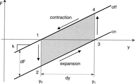
The loading conditions that maximize the work output are represented by the work cycle and indicated by the shaded region in Figure 2.10. The work cycle is generated by constraining the displacement of the unloaded un-charged actuator (state 1). A voltage is applied while holding the length constant, which is equivalent to adding the weight dF in the spring model (state 2). While keeping the electric field constant, the constraint is moved until the actuator force is zero (state 3). The voltage is then removed and the process is repeated. The area enclosed by a counter-clockwise work cycle corresponds to the work output per cycle. It is evident that the actuator force is not constant as it reaches its maximum force (dF) at the beginning and diminishes to zero.
This model assumes a quasi-static measurement. However, the viscoelastic properties of the polymer film cause the measured forces to be time dependent. A more sophisticated method that allows the determination of actuator power is the workloop
technique, which is popular for characterizing biological muscles [Josephson, 1985; Meijer et al., 2001].
Although simple, the quasi-static spring model was found to be a very effective tool for actuator design and is sufficient to illustrate the actuator tuning that was performed to achieve effective binary operation.
F F 4 of f contraction 1on k 3 dF yo yi
Figure 2.10. Linear quasi-static dielectric elastomer actuator model
2.3.3 Linear Actuators Prototypes
In comparison to the fixed frame actuator presented in Figure 2.2, for a simple linear actuator, expansion of the film is desirable to occur only in one planar direction. Constraining the film in the passive direction will cause the thickness compression to translate into expansion in the active direction. A constraint can be achieved mainly by pre-stretching the film in the passive direction. The non-linear elastic properties of the elastomer cause the film to stiffen with pre-straining, producing an output motion that is predominantly perpendicular to the high pre-strain direction. Figure 2.11 shows a fixed frame actuator expanding in only one planar direction. The maximum linear strain of about 240% was reached within 3 seconds. Reported values for the maximum area strains achieved by non-uniform stretching are larger than with isotropic pre-stretching [Pelrine et al., 2000]. This is believed to be due to the fact that non-isotropic
pre-stretching increases the dielectric strength without increasing the material stiffness in the output direction.
high pre-strain direction
a) Voltage: off b) Voltage: 10kV; relative strain: 240% Figure 2.11. Fixed frame actuator with motion in only one planar direction
Figure 2.12a shows an example of a linear actuator lifting a mass of a 150g by 6mm. The actuator film undergoes a linear strain of 40% and weighs less than 0.1g. The high force to weight ratio shows promise; however, there are some limitations associated with such an implementation.
The vertical sides of the film are free, allowing the film to bow in. From Figure 2.12b it is evident that the amount of pre-stretching in the passive direction is not uniform throughout the actuator film. Since the film is largely incompressible, it is thin close to the beams and thicker at the center. Applying an electric potential across the electrodes creates a non-uniform pressure and deformation of the film. Thus, not all areas of the film are actuated fully. Since the film is not constrained in the passive direction, it exhibits some motion in that direction upon actuation. This motion does not produce useful mechanical work. The challenge is to maintain the pre-stretched boundary conditions on the film without interfering with the desired motion of the actuator. One way to ensure uniformity in the film would be to increase the aspect ratio of the actuator. However, an extremely short and wide actuator would be inappropriate for many applications.
Another limitation of this type of actuator is that it can only work under tension, as the film would immediately buckle under compressive loading. These limitations can be addressed by integrating the actuator into a flexible frame.
a) Actuator lifting 150g b) Vertical edges of actuator bow in; elastomer film is not uniformly pre-stretched
Figure 2.12. Linear parallel beam actuators
2.4 Flexible Frame Actuator
The main purpose of the flexible frame is to maintain the boundary conditions on the film and provide a restoring force in the active direction.
2.4.1 Design
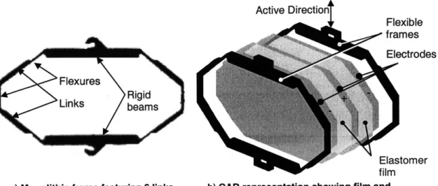
Since the actuator motion is intended to be linear, two parallel beams are used as the starting point for the frames. These beams are connected with a linkage that does not collapse under the tension of the film and does not interfere with the intended motion of the actuator. The geometry was chosen such that all areas of film undergo approximately equal expansion under actuation. This is necessary to ensure that the thickness remains uniform for the range of motion. Figure 2.13a shows a monolithic frame that was machined from a single piece of Delrin@. Flexibility is achieved by reducing the wall width of the frame border in the areas that function as hinges.
Figure 2.13b shows an exploded view of the actuator module with the stretched dielectric film integrated into its flexible frame. Higher actuation forces can be achieved by increasing the number of layers of film sandwiched between the frames. When using an even number of dielectric films, the electrodes can be arranged so that the two outer electrodes are both grounded. The high voltage is only present in the inside of the actuator and is thus shielded from the environment. The actuator module that was developed for the BRAID uses two layers of the dielectric polymer film.
Active Directiont
Flexible frames
.Electrodes
Figure 2.14 shows a photograph of a flexible frame module before and after actuation. VHBTm 4910 was used for the polymer film and silver grease for the electrodes. The electrical connections to the electrodes were made with small strips of
adhesive copper tape.
off on MTe g
dyt
Figure 2.14. Prototype offlexible frame actuator
A welcome side effect of the frame is that it significantly increases actuator shelf life. A common failure mode of the parallel beam actuator is tearing of the elastomer film. Due to the high strain of the material it is very sensitive to imperfections. Small cracks along the edges have a tendency to grow and eventually to propagate through the entire film, destroying the actuator. The frames counter this failure mode, as they provide a rigid border and inhibit the propagation of cracks. For the parallel beam actuator shown Figure 2.12b, the electrodes do not extend all the way to the edge of the film. This is to prevent arching around the edges of the film, which is a result of electric
a) Monolithic frame feat connected by flexures
Elastomer film
uring 6 links b) CAD representation showing film and electrodes
Figure 2.13. Flexible frame actuator module Flexures
Rigid)
Links bems
charge traveling through the air from one electrode to the other. The flexible frame has shown to eliminate this risk. The frame does, however, reduce the range of motion by adding additional stiffness to the module.
2.4.2 Performance
Figure 2.15 shows the measured force-displacement curves the actuator module at OkV, 5.5kV, and completing a work cycle. The stiffness curves are recorded by stretching the actuator and returning it to the original state. Some hysteresis is evident, which is attributed to the viscoelastic losses of the film and frame. To approximate the quasi-static behavior, the displacement was varied at a relatively slow rate during the measurement. The data for each of the three measurements was recorded over a period of 20 seconds. Both the flexible frame and the acrylic polymer contribute to the stiffness of the module, which is approximately constant over the range shown. This suggests that the Hookean model is sufficient in describing the quasi-static elastic behavior of the module. The isometric force (dF) is 2N, the stroke (dy) is 4mm, and the actuator stiffness
(k) is 0.5N/mm. actuator force-displacement 4-3- uncharged load line 2-work cycle z 0) 0 0- 6 arged load line -2-.31 13 14 15 16 17 18 19 20 21 22 length-y (mm)
Figure 2.15. Force-displacement characteristics offlexible frame actuator