HAL Id: cea-02470093
https://hal-cea.archives-ouvertes.fr/cea-02470093
Submitted on 7 Feb 2020
HAL is a multi-disciplinary open access
archive for the deposit and dissemination of
sci-entific research documents, whether they are
pub-lished or not. The documents may come from
teaching and research institutions in France or
abroad, or from public or private research centers.
L’archive ouverte pluridisciplinaire HAL, est
destinée au dépôt et à la diffusion de documents
scientifiques de niveau recherche, publiés ou non,
émanant des établissements d’enseignement et de
recherche français ou étrangers, des laboratoires
publics ou privés.
Characterizations and first plasma operation of the
WEST load-resilient actively cooled ICRF launchers
W. Helou, F. Durodié, Julien Hillairet, E. Lerche, G. Lombard, D. Milanesio,
P. Mollard, J.-M Bernard, N. Charabot, F. Clairet, et al.
To cite this version:
W. Helou, F. Durodié, Julien Hillairet, E. Lerche, G. Lombard, et al.. Characterizations and first
plasma operation of the WEST load-resilient actively cooled ICRF launchers. 23rd Topical Conference
on Radiofrequency Power in Plasmas (RFPPC 2019), May 2019, Hefei, China. �cea-02470093�
Characterizations and first plasma operation of the WEST
load-resilient actively cooled ICRF launchers
W. Helou
1,a), F. Durodié
2, J. Hillairet
1, E. Lerche
2, G. Lombard
1, D. Milanesio
3, P.
Mollard
1, J.-M. Bernard
1, N. Charabot
1, F. Clairet
1, L. Colas
1, Y. Moudden
1, B.
Santraine
1, Y. T. Song
4, G. Urbanczyk
1, R. Volpe
1, Y. S. Wang
4, Q. X. Yang
4, V.
Bobkov
5and the WEST Team
6.
1CEA, IRFM, F-13108 St-Paul-Lez-Durance, France 2LPP-ERM/KMS, TEC Partner, Brussels, Belgium 3
Department of Electronics, Politecnico di Torino, Torino, Italy
4Institute of Plasma Physics, Chinese Academy of Sciences, Hefei 230031, China 5Max-Planck-Institut für Plasmaphysik, Boltzmannstr. 2, 85748 Garching, Germany
6http://irfm.cea.fr/WESTteam a)
Corresponding author. New address: ITER Organization, Route de Vinon-sur-Verdon, CS 90 046, 13067 St. Paul Lez Durance Cedex, France. Email: [email protected].
Abstract. The paper discusses the characterization of the three high power steady-state and load-resilient ICRF launchers
of WEST before their installation in the tokamak. These launchers have been characterized and validated in low-power experiments (milliwatt range) as well as in experiments at the nominal RF voltages and currents in the TITAN vacuum chamber (~30 kV and 915 A peak). The successful commissioning of two of the launchers during the WEST C3 campaign at ~1 MW power level is illustrated. Manual and real-time controlled impedance-matching of the launchers are discussed, as well as the validation of their load-resilience. Furthermore, several redundant and complementary protection systems have been validated and are reviewed in the paper.
OVERVIEW OF THE WEST ICRF SYSTEM
The WEST ICRF system [1, 2] is constituted from three identical sub-systems. The specifications per sub-system are the following: (1) high power and CW operation (up to 3 MW / 30 s or 1 MW / 1000 s), (2) active cooling, (3) a 48 to 60 MHz frequency operation range with a nominal frequency of 55.5 MHz, (4) load-resilience for operation on ELMy H-mode plasmas with a VSWR below 2:1, and (5) a maximum electrical field of 2 kV/mm peak everywhere inside the launchers. As sketched in Fig.1(a), each sub-system includes: (1) one launcher with two RF power inputs, (2) a set of two ~40 m / 30 Ω circular coaxial transmission lines including DC blocks and bi-directional couplers located at about 4 m from the launchers inputs, and (3) two RF generators based on 3-stage tetrode amplifiers. The bi-directional couplers allow measuring the incident and reflected powers at the launchers inputs (amplitude and phase). WEST ICRF launchers (Fig.1(a) and Fig1.(b)) have each 2x2 straps covered by a Faraday Screen and are based on the so-called Internal Conjugate-T (ICT) impedance-matching circuit [1, 3]. The ICT configuration leads to a compact, hence low-loss, resonant structure. The ICT circuit of the WEST ICRF launchers includes variable vacuum capacitors, so-called bridges (ideally acting as 3-branch nodes), and 3 to 30 Ω wideband two-stage quarter-wavelength impedance transformers (see next section). WEST ICRF launchers are fully water cooled (70°C / 30-bar and 20°C / 4 bar). They are compatible with operation under high vacuum and high temperature (10-5 Pa, ~200°C), high electric fields (2 kV/mm leading to 30 kV peak voltages at the straps inputs) and high RF currents (915 A peak at the straps inputs). The 2 kV/mm value is a typical maximum allowed electric field value in vacuum for ICRF
launchers, see for instance the ITER ICRF launchers in [4]. The 915 A value corresponds to the nominal matching capacitors RF current as specified by the manufacturer. Each launcher is equipped with a set of 4 D-dot voltage probes [5] (see Fig.1(b)) which allow monitoring the voltages at the straps inputs (amplitude and phase). The RF design, mechanical design and construction of the WEST ICRF launchers are detailed in respectively [1], [6, 7] and [8].
It should be noted that the WEST ICRF launchers are the first ICRF launchers to combine: (1) high power operation capabilities (MW-level), (2) full active cooling for steady-state operation (up to 1000s), and (3) load-resilience for operation on ELMy H-mode plasmas. Furthermore, the WEST ICRF launchers are equipped with several redundant and complementary protection systems (see the last section). In addition, as will be illustrated through the following sections, the launchers’ RF reponse is in line with the RF design and is in agreement with numerical modeling. These aspects are of high relevance for future ICRF launchers such as those of ITER, CFETR and DEMO. Two launchers (hereafter, ANT1 & ANT2) have been installed and commissioned on WEST during the so-called C3 campaign (2018). The third launcher (ANT3) has been installed during the shutdown between C3 and C4 campaigns (2019).
(a) (b)
FIGURE 1. (a) Illustration of a WEST ICRF sub-system. The service-stubs allow injecting water-cooling pipes into the inner
conductors. The length of the service stubs is about quarter-wavelength at 55 MHz. A Resonant Double Loop (see next section) is sketched in yellow over the launcher’s CAD view. (b) A picture of the front face of a WEST ICRF launcher. The arrows indicate
the ideal RF current direction for a dipole configuration. The subplot is a picture of a D-dot voltage probe.
THE INTERNAL CONJUGATE-T, ITS IMPEDANCE MATCHING AND ITS
LOAD-RESILIENCE
It should be mentioned at first that while the straps’ reactance (X) can be considered as constant to the first order [9, 10, 11], the coupling resistance (R) is very much dependent on the edge density profile. Thus, it is a very non-stationary parameter (R is also inversely proportional to the square of the straps currents and voltages, and hence should be maximized, for instance using gas puffing [12]). It should be also mentioned that, if for a given coupling resistance, R0, the straps were matched separately using fixed two-port lossless matching networks, the VSWR
would vary as R0/R or R/R0 [11]. This case will be considered as the reference non-resilient case through the paper.
Knowing that R is typically halved at an L-H transition and increased by a factor 4-5, or even more, during ELMs (see for instance Figure IV – 63 of [11] for the JET ILA [13, 14]), the VSWR can reach unacceptably large values for the non-resilient matching case. Now, it should be mentioned that generally, a real-time controlled matching cannot be a solution to cope with coupling resistance non-stationarity. Indeed, the matching elements are generally electromechanical elements, while the coupling resistance can vary in a quasi-periodic manner with ms and sub-ms time scales (example during ELMs); the time-variation of R is hence too fast to be tracked by a real-time controlled electromechanical matching system. Load resilient matching networks, providing inherently VSWR<VSWRmax
(typically VSWRmax=2:1) are hence required [15].
A Conjugate-T circuit [3] is a type of load-resilient matching circuits. It is studied in depth in [11] (see also [1, 13, 14, 16, 17]). In an Internal Conjugate-T (ICT) circuit, the straps are grouped in Resonant Double Loops (RDL) where each RDL (see Fig.1(a)) is a pair of poloidal straps connected to a pair of series matching capacitors (Ctop and
“point”. The ICT concept aims at setting the capacitors such a way that: (1) the two parallel impedances at the T-point are complex-conjugate, and (2) for a particular coupling resistance R0 for which a perfect impedance matching
is desired, the input impedance at the T-point, ZT, is equal to Z0T. Z0T is then transformed to Z0, which is the
characteristic impedance of the feeding transmission lines, by a “second stage” matching network. In an ICT, the matching condition of an RDL (VSWR=1, or ZT-Z0T=0) can be expressed as a second order equation having two
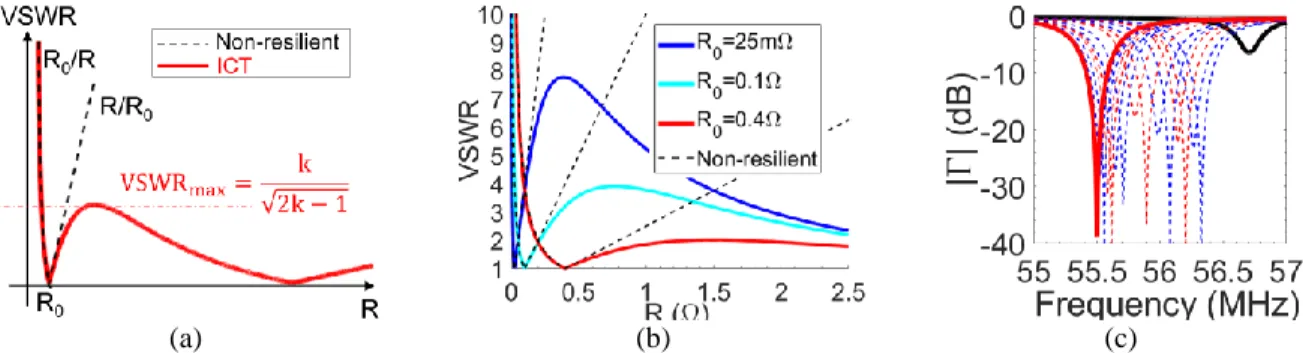
distinct solutions for the straps impedances; see the variation of VSWR as function of R in Fig.2(a). The local maximum (VSWRmax=k/√(2k−1), where k=Z0T/R0) is an increasing function of k for Z0T>R0 (which is typically the
case). As an example, VSWRmax is equal to 7.8, 3.9 and 2 for k equal to 120, 30 and 7.5, respectively. It can be
understood from Fig.2(a) that the ICT circuit is indeed load-resilient since VSWR is better than R0/R or R/R0 and
ensures a VSWR below VSWRmax for a broad range of coupling resistances. Knowing the estimated coupling
resistance for WEST ICRF launchers using the TOPICA code [18, 19], see [1, 11], a couple [R0; Z0T] = [0.4;
7.5×0.4=3] Ω has been found to be the best working point for these launchers. Thus, it has been chosen to implement a 3 to 30 Ω two-stage quarter-wavelength impedance transformer as the second stage matching network. The theoretical variation of VSWR as function of R is shown in Fig.2(b) for the WEST ICRF launchers and for several values of R0 (R0=0.4 Ω is the “sweet point” as it provides a VSWR below 2:1 for a broad range of R).
(a) (b) (c)
FIGURE 2. (a) VSWR as function of R for the ICT. The non-resilient case is shown as a reference. (b) Theoretical variation of
VSWR as function of R for the WEST ICRF launchers and for R0=3/120=25mΩ, 3/30=0.1Ω and 3/7.5=0.4Ω. (c) An example of
an RDL manual tuning at 55.5 MHz. Black: starting point. Blue: Ctop,i>Ctop,i-1 & Cbot,i=Cbot,i-1. Red: Ctop,i=Ctop,i-1 & Cbot,i>Cbot,i-1
where i is the iteration index.
In an ideal case, the capacitances required to match an RDL can be found analytically [1]. However, in realistic conditions, the system suffers from imperfections (for instance, the bridge is not an ideal 3-branch node, the capacitors include stray elements such as self-inductances [11]), asymmetries and mutual couplings. Furthermore, the experimental, full and complex-valued straps’ S-matrix is generally unknown. Manual tuning procedures are hence required. Manual tuning of an RDL is performed as follows. First, sufficiently small capacitances values are taken. Second, one capacitance is increased at a time until min(|Γ|i+1)>min(|Γ|i) where Γ is the reflection coefficient,
and i is the iteration. Third, one switches to the other capacitor and repeat the second and third steps until a satisfactory impedance-matching is obtained at the requested frequency. The process is sketched in Fig.2(c). It should be noted that an ICT features two matching solutions (1st solution: Ctop>Cbot, 2nd solution: Ctop<Cbot) [11];
manual strategies have been in addition developed to achieve the second matching solution starting from the first one (and vice versa). At this point, one may wonder how to manually tune a full-launcher (two RDLs in presence of mutual couplings) on plasma around a frequency F0. The matching is performed as follows. The launcher is first
tuned under vacuum conditions (for example during vacuum conditioning): at F0, the left RDL is matched as
illustrated in Fig.2(c) while the capacitances of the right RDL are set to their maximum values (see Fig.3(a)). Then, the right RDL is matched at F0 for the same solution as the left RDL in the previous step, while the capacitances of
the left RDL are set to their maximum values (see Fig.3(b)). The four capacitors are then set to the matching values; both RDLs will be matched for a dipole excitation at an upshifted frequency of F0+ΔF0, see Fig.3(c) (the frequency
upshift is in particular due to mutual couplings). When the launcher is facing a load (such as the plasma), the launcher is not matched anymore (vacuum matching do not correspond to the “sweet point”, as seen in Fig.2(b)), see Fig.3(d). The capacitances should then be moved apart by 2×ΔC (depending on the solution, top or bottom capacitances should be increased by ΔC, the other ones should be decreased by ΔC) and both RDLs will be matched for a dipole excitation at a frequency F0+ΔF1 where ΔF1 is slightly larger than ΔF0 (see Fig.3(e)). It is interesting to
step can be progressively repeated (increase of ΔC and ΔF) such as to enhance the impedance-matching (see for instance Fig.7(a)) .
Automatic and real-time controlled matching can be also very useful. In fact, manual tunig can be delicate due to the large Q~X/R values and due to the mutual couplings. Furthermore, real-time controlled matching can be used to automatically set the working point for the capacitances, in particular at yet unexplored frequencies (look-up tables are filled in low-power pre-characterizations and serve as starting point for launchers’ impedance matching in the tokamak; these look-up tables are however filled only at a given set of discrete frequencies). In addition, real-time controlled matching can relax the constraints on the load-resilience [13]. Several matching algorithms have been studied in [11], in particular, the “Real-Imag” algorithm [20, 21], which has been chosen for the automatic tuning of the WEST ICRF launchers. This algorithm is also employed on the JET ILA [13, 22]. First, the impedance (Zcoupler)
seen at a launcher’s bi-directional coupler (see Fig.1(a)) is measured. Second, the impedance at the T-point (ZT) is
computed. This calculation involves: (i) an S-matrix (SSWIT) obtained from HFSS modeling and corresponding to
the cascade connection of the service-stub, RF-window and impedance-transformer, and (ii) a measured S-matrix (Spath) corresponding to the wave-guiding path from the bi-directional coupler position to the launcher’s input
(including a DC-block and articulated transmission lines). Note that in order to measure Spath, arrangements of
specific endcaps (and optional 30 to 50 Ω impedance transformers) are required to connect the 30 Ω transmission lines to a Vector Network Analyzer (VNA); these arrangements were calibrated beforehand by a Thru-Reflect-Line process [11] and properly de-embedded from Spath. Third, error signals, ε, relating the extracted T-impedance (ZT)
and the requested value for ZT (ZTR) are computed. Finally, a vector, VC, proportional to the capacitors velocities, is
calculated by a matrix product between ε and T, where T is a matrix extracted from the linearization of ε around the matching point [11]. The matching algorithm together with scenarios for operation on plasma have been extensively simulated, as detailed in [11, 20, 21]. These simulations involve S-matrices extracted from full-wave calculations (TOPICA for the straps and HFSS for the vacuum parts) and RF network computations using SIDON [21].
(a) (b) (c) (d) (e)
FIGURE 3. Example for the manual tuning of a full-launcher (see text). The black, magenta and orange vertical line correspond
respectively to F0, F0+ΔF0 and F0+ΔF1. Here F0=55.5MHz. The data is obtained from numerical modeling involving S-matrices
computed on HFSS and RF network computations performed on SIDON [21].
THE CHARACTERIZATION OF THE LAUNCHERS BEFORE THEIR
INSTALLATION IN THE TOKAMAK
Before their installation in the tokamak, WEST ICRF launchers undergo three category of pre-qualifications tests. These tests are performed in order to validate the launchers before their installation in the tokamak (risk and delays mitigation), as well as to accelerate their commissioning (gain in experimental time on plasma). The 1st category of tests are low-power (milliwatt range) tests performed using a VNA. These tests are detailed below. The 2nd and 3rd category of tests are performed in the TITAN vacuum chamber. The 2nd category of tests are vacuum-leak tests conducted at ~10-5 Pa and ~150°C. The 3rd category of tests are high RF voltage and current tests (915 A and ~30 kV peak) that aim at validating the launchers front-faces at the nominal RF currents and electric fields. It is interesting to note that it typically takes up to 400 RF shots of 20 ms duration before one can start increasing the RF pulse duration [23]. The 2nd and 3rd category of tests are detailed in [23].
The low-power tests aim at (1) validating the launchers RF design and frequency operation range (they also allow performing comparisons in between the launchers), (2) validating the launchers’ load-resilience by sweeping the gap between the launcher and a dummy load. The low-power tests can also allow: (3) filling look-up tables for the matching element settings, (4) validating strategies for the launcher’s manual tuning, (5) validating strategies for
the launcher’s automatic tuning, (6) assessing the launchers coupling capabilities, and (7) benchmarking with modeling. These aspects allow accelerating the commissioning and the operation of the launchers on plasma. They also allow using numerical modeling to assist in decision making in the control room.
A low power dummy-load has been developed [11] and installed in TITAN [23]. It is based on a glass aquarium lying on a linear guiding system and hosting media with a high-amplitude complex-valued dielectric permittivity (εr). A handle allows sweeping the gap (D) between the aquarium and a launcher in a 0 to 10 cm range. Since the
coupling decreases with the launcher to load gap, sweeping D allows testing the launchers load-resilience. Two candidate media have been evaluated: an available BaTiO3 mixture [24] and salty-water. The former is not optimal
at ~50 MHz (it has been optimized to test ICRF launcher reduced-scale mockups at about 200 MHz) and does not provide significant coupling enhancement when compared to optimized salty-water [11]. Salty-water has thus been chosen and the salt concentration has been optimized in dedicated experiments with a Tore Supra launcher [11], see Fig.4(a) . Note that the optimal salinity, σopt of Fig.4(a), is similar to the water salinity values reported in [25].
The WEST ICRF launchers have been successfully validated in the low power experiments. Good agreement with numerical modeling has been observed. The low-power characterizations demonstrated that the launchers are tunable in the 48 to 60 MHz frequency range, and even beyond (~38 to ~74 MHz). Look-up tables for the matching elements settings have been filled at several frequencies. In addition, the overlap of the capacitors’ electrodes have been found to agree well with modeling (the vacuum capacitors are based on the cylindrical concentric electrode technology [26], as sketched in the subplot of Fig.4(b)). An agreement better than |±1.5mm| has been found for all capacitors except one, possibly due to a less-precise calibration of its electrodes reference position (note that the electrodes overlap full range is 50 mm). Furthermore, the launchers load-resilience has been successfully demonstrated as illustrated in Fig.4(c). Indeed, it is seen that the variation of the VSWR with coupling follows patterns similar to the ones of Fig.2(a).
(a) (b) (c)
FIGURE 4. (a) Optimization of the dissolved salt concentration (numerical modeling is detailed in [11]). (b) Agreement of the
measured capacitors’ electrodes overlap with modeling for the three launchers. Overlap measurements have been performed at several frequencies for ANT3. (c) Validation of the load-resilience in low-power experiments. R is changed by sweeping the
launcher to load gap (D).
The manual impedance-matching strategies have been validated in low power experiments. In particular, the experimental values for ΔC and ΔF (see the previous section) agree well with numerical modeling, see Fig.5(a) and Fig.5(b). The “Real-Imag” algorithm has been also validated in low-power experiments. A VNA’s first port excited a launcher at ~40 m from its inputs. The VNA’s second and third ports were connected to a bi-directional coupler at ~4 m from the launcher’s input (see Fig.1(a)). The measured S-matrices have been processed by a computer, Zcoupler
and ZT have been extracted, and the matching algorithm computed the error signals that drove the variation of the
capacitances values (in these tests the capacitances were varied manually). As can be seen in Fig.5(c), impedance-matching has been successfully achieved in several iterations, validating the automatic impedance-matching algorithm. It is interesting to note that the signals at the various iterations have been reproduced by modeling when considering the same values of C-Cm as in experiments (see grey-shaded subplots in Fig.5(c)).
(a) (b) (c)
FIGURE 5. (a&b) ΔC and ΔF of the manual tuning strategy (see text). Good agreement is observed with modeling. With these
settings, the VSWR is less than 1.05 (resp. 1.2) in modeling and low-power experiments (resp. on plasma). (c) Validation of the automatic matching algorithm. White (resp. grey) shaded plots: experiments (resp. modeling). Cm is a capacitance value at the
final iteration corresponding to matching.
FIRST EXPERIMENTS ON PLASMA
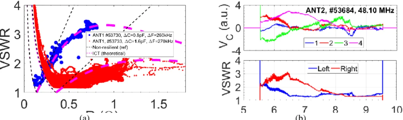
ANT1, ANT2, their corresponding generators, the CODAC, a new 100 kHz acquisition system, and various protection systems (see next section) were successfully commissioned during the WEST C3 campaign. The ICRF system pulsed in about ~190 plasma shots. The operation frequency has been set according to the central magnetic field (~48 MHz in #53566-53706 and ~55.5 MHz in #53730-54087). The ICRF coupled power achieved 1 MW / 1 launcher (see Fig.6(a)) and up to 1.4 MW / 2 launchers (see Fig.6(b)). In addition, the load-resilience has been successfully demonstrated on plasma for both ANT1 and ANT2 (see Fig.6(c)) and is in agreement with modeling.
(a) (b) (c)
FIGURE 6. (a) 1 MW of coupled power with ANT2. (b) The ICRF power achieved 1.4 MW / 2 launchers just before a plasma
crash. (c) The demonstration of the load-resilience on plasma and agreement with modeling. The non-resilient case is shown for reference. Numerical modeling is detailed in [11, 20, 21].
The manual impedance matching of the launchers has been successfully performed following the strategy discussed earlier in the paper, see Fig.7(a). In shot #53730 the ICRF system has pulsed for the first time on WEST plasmas at ~55.5 MHz. The capacitors have been set accordingly to look-up tables filled during low-power experiments in vacuum, but moved apart by 2×ΔC=2×0.8 pF following the manual tuning strategy. The frequency increment has been set to ΔF=260 kHz. By the second shot at ~55.5 MHz (#53733), a “sweet point” was already found (ΔC=1.6 pF and ΔF=270 kHz). This stresses again on the good agreement with modeling, as well as on the importance of the modeling and the low-power experiments. Note the agreement of ΔC and ΔF as obtained on plasma with ΔC and ΔF obtained from modeling and low power experiments, see Fig.5(a) and Fig.5(b). In addition to the manual tuning, automatic feedback-controlled impedance-matching has been implemented, validated and routinely employed on plasma. An example is illustrated in Fig.7(b). In future experiments on plasma, assessments will be performed to accelerate the convergence to the matching point.
(a) (b)
FIGURE 7. (a) The successful employment of the manual tuning strategy in experiments on plasma. (b) Operation of the
real-time controlled impedance-matching. Top: real-time-traces for VC (the vector of signals that are proportional to the capacitors
velocities). A positive (resp. negative) value for VC leads to a capacitance increase (resp. decrease). Bot: time-traces of the
VSWR.
PROTECTION SYSTEMS
Several arc detection systems protect the WEST ICRF system. Whenever an arc is detected in a sub-system, its RF generators are automatically tripped, typically within ~10 µs. The power is then re-applied after 30 to 50 ms depending on the arc detection system that has detected the arc. This is a way to identify in post-processing which arc detection system has tripped the power. The RF generators are definitely switched-off if a given number of trips occurred within a given sliding time-interval (typically 30 interruptions during 1s). The following arc detection systems are implemented:
1) & 2) Power Reflection Coefficient (PRC) measurements at the launchers inputs (1) (using the bi-directional couplers of Fig.1(a)) and at the generators (2). The PRC threshold for arc detection is typically set to about 0.4. As it is not possible to detect arcs occurring at low impedance regions using PRC measurements [27], the following arc detection systems are also implemented.
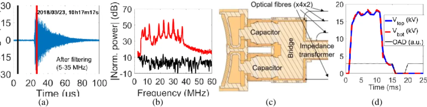
3) The Sub-Harmonic Arc Detection (SHAD) system [28]. At the operation frequency, the generators and the launchers are tuned to 30 Ω (the characteristic impedance of the transmission lines); they are fully mismatched at all other frequencies. A sub-system (from the launchers to a generator) thus acts as a sort of cavity having its characteristic resonant frequencies. At the same time, an arc is a fast transient event (hence broad spectrum event). When an arc occurs, it excites the large cavity at its resonant frequencies; a bi-directional coupler installed at a generator output measures a reflected wave such as the one indicated in Fig.8(a) and Fig.8(b). A detection system connected to the bi-directional coupler and operating at 5-35 MHz hence detects the arcs [28]. It should be noted that parasitic events have triggered false arc detection by the SHAD system [29] on JET (such as ion cyclotron emissions and breakdown events in the NBI system) and AUG. No false trips were detected on Tore Supra nor on WEST so far, still an R&D is ongoing on the implementation of an FPGA-based SHAD system which should be able to discriminate arcs from spurious noise.
4) An optical arc detection system protects the low impedance regions, namely at the bridges and the connection to the impedance transformers. At these locations, optical fibres are installed (see Fig.8(c)). The fibres feature an optical beam-width of about 20°. The optical system operates in the visible spectrum. Dedicated vacuum-compatible lamps are installed at the bridges and allow automatically testing the optical arc detection prior to each RF shot. An optional high pass electronic filter can be used to discriminate fast light emissions (due to arcs) from spurious plasma-generated radiation. The optical arc detection system has been successfully validated in the high RF voltage / RF current tests in the TITAN vacuum chamber (see Fig.8(d)). So far, no trips have yet been identified on plasma, possibly due to faster arc detection by the PRC measurements or the SHAD.
Several other systems protect the WEST ICRF launchers such as (1) real-time vacuum measurements in the impedance-transfomers (see Fig.1(a)) with a threshold of ~3.5 mPa for power tripping and (2) a real-time control of the incident powers (~10 µs time scale) protecting the launchers from any possible overuccrents and overvoltages.
(a) (b) (c) (d)
FIGURE 8. (a) Typical arc signature as measured by the SHAD system. (b) Short-term Fourier transforms at the 2 µs black and
red time-intervals of (a). (c) Poloidal cross-section through a poloidal pair of straps illustrating the location of the optical fibres that are used for arc detection. (d) Validation of the Optical Arc Detection (OAD).
CONCLUSION
The three high-power, steady-state and load-resilient WEST ICRF launchers have been successfully pre-qualified and validated in low-power experiments and in tests in the TITAN vacuum chamber. Two launchers were successfully commissioned during the WEST C3 campaign at a ~1 MW power level. Several redundant and complementary protections systems have been validated. Manual tuning and real-time controlled impedance matching have been successfully performed. The RF response of the launchers is in line with the RF design and agrees with modeling. These results provide good confidence for the future operation of the WEST ICRF launchers.
REFERENCES
1. W. Helou, et al., Fusion Eng. Des. 96–97 (2015) 473–476. 2. J. Hillairet, et al., AIP Conf. Proc. 1689, 070005 (2015). 3. G. Bosia, Fusion Sci. Technol. 43 (March (2)) (2003) 153–160. 4. F. Louche, et al., this conference.
5. W. Helou, et al., Rev. Sci. Instrum. 87, 104705 (2016). 6. Z. Chen, et al., Fusion Eng. Des. 94 (2015) 82–89. 7. K. Vulliez, et al., Fusion Eng. Des. 96-97 (2015) 611. 8. J.-M. Bernard, et al., Fusion Eng. Des. 217-222 (2017) 123. 9. M. Evrard, et al., AIP Conf. Proc. 787, 186 (2005).
10. F. Durodié, et al., Fusion Eng. Des. 66-68 (2003) 509-513.
11. W. Helou, Ph.D. thesis, Aix-Marseille University, CEA-Cadarache, 2017. 12. G. Urbanczyk, et al., this conference.
13. F. Durodié, et al., Fusion Eng. Des. 123 (2017) 253–258. 14. P. Dumortier, et al., Fusion Eng. Des. 123 (2017) 285–288. 15. J.-M. Noterdaeme, et al., Fusion Eng. Des. 74 (2005) 191–198. 16. A. Argouarch, et al., Fusion Eng. Des. 84 (2009) 275–278. 17. I. Monakhov., et al., Nucl. Fusion 53 (2013) 083013. 18. V. Lancellotti, et al., Nucl. Fusion 46 (2006) S476–S499. 19. D. Milanesio et al., Nucl. Fusion 49 (2009) 115019.
20. W. Helou, et al., 9th Europ. Conf. on Ant. and Prop., Lisbon, Portugal, 12-17 April 2015. 21. W. Helou, et al., AIP Conf. Proc. 1689, 070004 (2015).
22. F. Durodié, et al., AIP Conf. Proc. 1689, 070013 (2015).
23. J.-M. Bernard, et al., Fusion. Eng. Des. (2019), https://doi.org/10.1016/j.fusengdes.2019.03.033. 24. P. Dumortier, et al., Fusion Eng. Des. 96–97 (2015) 463–467.
25. A. Messiaen, et al., Fusion Eng. Des. 74 (2005) 367–375.
26. L. Giers, COMET Variable Vacuum Capacitors, Service Bulletin-12. 27. R. D'Inca, AIP Conf. Proc. 1406, 5-12 (2011).
28. G. Berger-By, et al., Fusion Eng. Des. 82 (2007) 716–722. 29. P. Jacquet, et al., AIP Conference Proceedings 1406, 17 (2011).


![FIGURE 4. (a) Optimization of the dissolved salt concentration (numerical modeling is detailed in [11])](https://thumb-eu.123doks.com/thumbv2/123doknet/12981302.378345/6.918.116.828.540.761/figure-optimization-dissolved-salt-concentration-numerical-modeling-detailed.webp)