Publisher’s version / Version de l'éditeur:
Vous avez des questions? Nous pouvons vous aider. Pour communiquer directement avec un auteur, consultez la première page de la revue dans laquelle son article a été publié afin de trouver ses coordonnées. Si vous n’arrivez pas à les repérer, communiquez avec nous à PublicationsArchive-ArchivesPublications@nrc-cnrc.gc.ca.
Questions? Contact the NRC Publications Archive team at
PublicationsArchive-ArchivesPublications@nrc-cnrc.gc.ca. If you wish to email the authors directly, please see the first page of the publication for their contact information.
https://publications-cnrc.canada.ca/fra/droits
L’accès à ce site Web et l’utilisation de son contenu sont assujettis aux conditions présentées dans le site LISEZ CES CONDITIONS ATTENTIVEMENT AVANT D’UTILISER CE SITE WEB.
Technical Translation (National Research Council of Canada), 1968
READ THESE TERMS AND CONDITIONS CAREFULLY BEFORE USING THIS WEBSITE.
https://nrc-publications.canada.ca/eng/copyright
NRC Publications Archive Record / Notice des Archives des publications du CNRC :
https://nrc-publications.canada.ca/eng/view/object/?id=4b67c59e-f1f9-4814-9b55-a9a99d7353af https://publications-cnrc.canada.ca/fra/voir/objet/?id=4b67c59e-f1f9-4814-9b55-a9a99d7353af
Archives des publications du CNRC
For the publisher’s version, please access the DOI link below./ Pour consulter la version de l’éditeur, utilisez le lien DOI ci-dessous.
https://doi.org/10.4224/20386562
Access and use of this website and the material on it are subject to the Terms and Conditions set forth at
The behaviour of concrete products and precast reinforced concrete
members in a fire
Wierig, H. J.; National Research Council of Canada. Division of Building
Research
This paper describes the behaviour of materials
exposed to fire. The performance of precast concrete
and precast reinforced concrete when exposed to stand-ard fire test is analysed and the influence of the properties of the aggregates, the cement paste, and the reinforcing steel on fire endurance of the completed
assembly is discussed. The author Dr. Ing. H.
J.
Wierigwas formerly engaged in Fire Testing with the University of Braunschweig and is now with the Cement and Concrete Research Institute in Beckum, West Germany.
The Division of Building Research extends its thanks to Mr. D.A. Sinclair of the Translations Section of the National Research Council who translated this paper and to Mr. M. Galbreath of this Division who checked the translation.
Ottawa April, 1968
R. F. Legget Director
Technical Translation 1317
Title:
The behaviour of concrete products and precast reinforced
concrete members in a fire
(Das Verhalten von Betonwaren und Stahlbetonfertigteilen im
Feuer)
Author:
H.J. Wierig
Reference:
Betonstein-Zeitung, 29
(8):
SYUMセPW[(9):
セセSMセUャ[(10):
503-510, 1963
(Reprinted in Untersuchungen an Beton, 6: 3-31, 1964)
CONCRETE MEMBERS IN A FIRE
1. Introduction
Fire is one of the natural forces to which man has always been
exposed. From antiquity down to the present, history tells of many
cat-astrophic fires which destroyed whole villages and cities. At an early
date attempts were being made to profit by the experience gained from fire and to adapt the construction of buildings and to plan villages and cities
accordingly. As an example we may cite the well-known fire of London in
1666. At the time of reconstruction of the city, very extensive building
regulations were enacted(l). For example, the kinds of building materials
to be used were specified, and the width of the new streets was determined. These regulations can be regarded as the forerunners of our present-day regulations.
However, systematic research into the behaviour of building materials
and structures exposed to fire was only begun about 100 years ago. At first
the investigations were restricted to the burning down of old buildings
condemned to demolition(1,2). Later, systematic fire tests under
well-defined conditions were introduced. Today, in most countries, there are
well-defined standards and test procedures, and an international standard
is under preparation. In Germany fire tests are carried out under DIN 4102
"Resistance of building materials and members to fire and heat". This
standard is at present under revision. A draft of the testing regulations
contained in the revised version of this standard has just been pUblished. In the last 100 years a great deal of knowledge has been gained
about the behaviour of building materials and members in fires. Nevertheless,
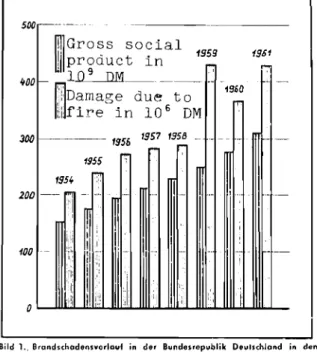
the damage caused by fire has continued to increase even in recent years. In
Figure 1 the finely hatched columns show the increase in damage due to fire in
the Federal Republic of Germany during the years 1954 to 1961(3). The growth
of the gross national products reduced 1000 times is shown for the same
period by the coarsely hatched cOlumns(4). It will be recognized that the
damage has been increasing at a somewhat faster rate than the gross national
product. Similar trends have been noted in other countries. Figure 1
illustrates very clearly that all economically feasible measures must be taken
in order to prevent any further increase of damage due to fire. In this
connection preventive structural fire protection acquires a special
the prevention, as far as possible, of the outbreak of ヲゥイ・セ
measures hindering the spread of fire; and provision of escape routes for the use of the inhabitants and occupants of a building in the event of a catastrophic fire.
For the prevention of the spread of fire damage the load-bearing and separating members of a building must resist the fire for a sufficiently long time, i.e. they must continue to exercise their intended functions. The required fire resistance time depends on the nature and function of the
building involved. For example, different regulations are applied to
ware-houses and theatres in the building codes than to small, ウゥョセャ・Mヲ。ュゥャケ
dwellings. Designing architects and engineers must have sufficient
know-ledge of the construction possibilities by which an adequate fire resistance. time can be attained in a given member.
In considering the behaviour of structural members in fire, two
basic cases must be distinguished. During a fire a construction is only
briefly, but very severely exposed. (For this unrepeated catastrophic case,
only a simple safety measure is required.) The state of the structure after
the fire, i.e. with a view to continued use, is only of secondary
consid-eration. For building compononents which have to withstand comparatively
high temperatures while performing their design functions, quite different
conditions prevail. This is the case, for example, in furnace construction,
and more recently in reactor design. Three different points of view must be
taken into account both in the selection of the building materials and in the structural design.
In many respects there is no fundamental difference between the
behaviour in fire of precast and poured-in-place concrete construction. The
present paper reviews the behaviour of concrete and reinforced concrete in fire and will discuss from individual examples the special properties of concrete products, precast reinforced concrete members, and the posqibility of improving the fire resistance time of individual members.
2. The Behaviour of Building Materials Exposed to Elevated Temperatures
2.1 General
With respect to the behaviour of building materials exposed to elevated temperatures, we can separate two broad classes, combustible and
non-combustible materials. Wood and many plastics, for example, are 。ュッョセ
the "combustible" building materials. At higher temperatures, they begin to
burn and are destroyed. Not so well-known is the fact that the
"non-combustible" materials, including concrete and steel, suffer an alteration of important mechanical properties as an effect of exposure to elevated
temper-atures. Regarding the behaviour of structures in fire, the following IJrOperties of the building materials and their changes due to higher temperatures are of importance:
1. Coefficient of thermal expansion;
2. strength, yield point, elongation at fracture and creep
be-haviour;
3.
modulus of elasticity;4.
thermal conductivity and specific heat.Moreover, changes in composition and structure of some building
materials can affect the behaviour of the construction セョ a fire. For
example, many rocks crumble on exposure to extreme heat.
We shall now review the most important changes that occur in concrete and building materials which are used in conjunction with concrete, due to the effect of higher temperatures.
2.? Mortar and concrete
2.21 Thermal expansion
Mortar and concrete are made up of cement, aggregates and water. The high temperature behaviour can differ considerably, depending on the mix,
the materials employed and especially the aggregates. While at room
temper-ature the mechanical properties of the solid concrete are determined primarily by the properties of the cement paste*, the high temperature behaviour, especially the coefficient of thermal expansion, is greatly in-fluenced by the aggregates as well, since they make up the greater part of
the volume of the concrete. Therefore, let us first consider the behaviour
of the aggregates.
The effect of the aggregates on the behaviour of mortar and concrete at higher temperatures depends primarily on their coefficient of thermal
expansion. The texture of a specimen of mortar and concrete can remain intact
in the presence of increasing temperatures only if the resulting changes of shape of the separate components are mutually compatible, and the internal
stresses can be absorbed by the cement paste. Hence, aggregates with a low
coefficient of thermal expansion and a temperature-expansion curve that is as
smooth as possible, behave best. Figure 2 shows the thermal expansion of
various aggregates as a function of the temperature(S,6). It will be noticed that for quartzitic rocks there is a characteristic discontinuity of the
thermal expansion between SOO and 600°C. This bend in the
temperature-expansion curve is due to the 。セs quartz conversion, which under laboratory
conditions takes place at S73°C with a heat consumption of approximately
8 cal/g. To be sure, the practical effects of quartz conversion is not as
serious a matter in a fire as it may appear to be at first glance. Contrary
to experiments with small specimens, structures in the fire are only slowly
heated from the outside in to a temperature above SOOoC. Structural
relaxation, therefore, proceeds only to a limited depth. Of course, if
concrete constructions that have been exposed to fire are to be used again, the affected layers must be r-emov ed .
With the exception of diabase, non-quartzitic rocks generally behave
better than quartzitic material. Among natural rocks, basalt and a number
of kinds of limestone are found to have favourable coefficients of thermal expansion, while artificial stones similarly endowed include blast furnace
slag fragments and crushed brick. Even for basalt, there is a 」イゥエゥ」。セ
temperature, at approximately 900°C. At this temperature the rock begins to
expand markedly, giving off gas.
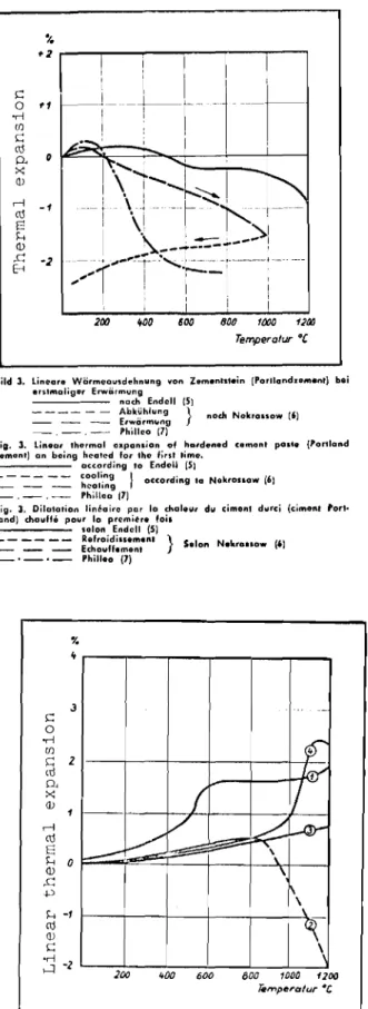
When mortars or concrete specimens are heated it is not only the
aggregates that expand. The cement paste also changes in volume. Figure 3
shows the change of volume of cement paste from Portland cement according to
Endell(S), Nekrassow(6), and Philleo(7). The numerical data of these
investigators differ. It is clear, however, that first a thermal expansion
occurs, which is subsequently compensated for and exceeded by the shrinkage
due to release of water. A further reduction of volume takes place on
cooling after heating. Probably the different results are due to different
compositions of the cement paste (water-cement ratios) and different rates of heating and different sizes of specimens.
Table I contrasts the various test conditions.
If the cement paste is heated not once, but several times, then, according to ref.(6) , a reversible positive expansion occurs from the second heating on (Figure 4).
Since the aggregates expand when exposed to heat, whereas the cement paste begins to shrink again at higher temperatures, the thermal expansion
occurring in concrete is less than the aggregate itself. Under otherwise
similar conditions the coefficient of thermal expansion decreases with
mortars are plotted as functions of temperature after Endell(S). All stones
of the same kind do not necessarily behave the same. Considerable variations
are possible among quartzitic material, and especially among limestones.
2.22 Strength
When specimens made from mortar and concrete are exposed to higher
temperatures their strength values are altered. Publications(6,8-1S) on
strength tests of mortar and concrete in a heated state are partly
contra-dictory. This is due on the one hand to varying test conditions (sDecimen)
size, mix, type of aggregate, age of the specimens, storage conditions,
heating times, time of testing after heating, water-cement ratio, construction of test furnaces, etc), and secondly to differences in the initial material.
The investigators fall into two groups. One group already found a decrease
in compressive strength for the comparatively slightly heated stage of about 200°C, which continued at a more or less steady rate at higher temperatures. Other tests, however, showed an increase of compressive strength up to about
300°C and a drop only on further heating. The initial increase of strength
on heating of certain concretes can be explained by the fact that heating brings about a "steam hardening", leading to additional hydration of the
cement. With many types of aggregates, moreover, a reaction between cement
and aggregate is by no means impossible.
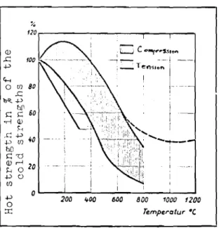
The vertically hatched area in Figure 6 shows the scatter range with-in which most of the results of concrete compressive strength tests at higher
temperatures fall. The data of Malhotra(ll), according to which the
water-cement ratio has no appreciable effect on the relative change of thermal
compressive strength, are interesting. Of greater influence, however, is the
ratio of cement to aggregates, which presumably can be attributed to the above-mentioned severe internal stresses arising between cement pastes and aggregates.
British investigations(16) showed that after exposure to temperatures up to about 300°C for several weeks no further decrease of strength could be expected (Figure 7).
According to French investigations(17), concrete tensile strengths
drop more rapidly than the compressive strength values. The scatter range
for the tensile strength is horizontally hatched in Figure 6. For a special
fireproof concrete, the compressive strength may be greater after very
severe heating than those indicated in Figure 6(6,12,lS). The increase of
broken-line curve, is due to the fact that in properly composed concrete the lost bond of hydration is replaced by a ceramic bond.
2.23 Mortulus of elasticity
When concrete is exposed to elevated temperatures, a decrease in the
modulus of elasticity occurs. This strongly affects the deformations in a
structure. Also affected is the interplay of external and internal forces in
statically indeterminate structures, in prestressed concrete constructions and even in standard, reinforced concrete cross-sections.
Some existing results of modulus of elasticity measurements at
higher temperatures differ sharply from each other. Figure 8 shows
Woolson1 s ( 1 8 ) results on diabase and limestone concrete, later confirmed
by Busch(9) on sandstone concrete (quartzitic). Woolson investigated
concretes with a cube strength of about 160 kg/cm2
• Busch's investigation
dealt with cube strengths of 280 kg/cm2• The compressive stresses were 30
to 50 kg/cm2• The very strong decrease of the modulus of elasticity even at
relatively low temperatures up to 4000
c
is striking. According to Woolsonand Busch, the modulus of elasticity at 4000
c
is only about 20% its value atroom temperature.
In more recent investigations(7,12,19) a slower rate of decrease of
the modulus of elasticity was found l)y Cruz and Philleo. The results of these
investigations are also plotted in Figure 8. However, in these tests, also,
the modulus of elasticity at 300oC, again fell to 40 to 50% of its value at
room temperature, depending on the water-cement ratio.
The difference between the results of Woolson and Busch on the one hand and those of Cruz on the other may be sought in the fact that according to Busch's findings the modulus of elasticity of a concrete that has been
exposed to fire increases with increasing load. This means that the ratio
of EcoId/Ewarm is more favourable when the tangent moduli are compared, not,
as usual, the secant moduli. For practical application, therefore, values
may be chosen which lie between those of Busch and Cruz, depending on the nature of the stress.
2.24 Heat conduction and specific heat
The internal heating of a structural member depends largely on the heat conductivity and the specific heat of the building materials employed.
con-Range I Range II Range III
sider the heat conduction of concrete, we must distinguish between three basic temperature ranges:
be10w oOe
between 0° and 1000e
above 1000e.
In conjunction with the behaviour of concrete structures in the presence of fire, range I is of interest only in a very few exceptional
cases. Normally, the initial temperature of a construction at the start of
a fire will be above oOe. For the sake of completeness, however, it must be
mentioned that a considerable delay in the internal heating of the structural members is due to the latent heat of melting of ice.
In range II the heat conduction (kcal/mhOe) of the concrete is
influenced primarily by its bulk density and its moisture content. Figure
9
shows these effects at room temperature(20). The specific heat of regular
air-dry heavy concrete at room temperature can be taken as 0.21 - 0.25 kcal/
kgOe.
In Figure 10, with the example of an aerated concrete having a
bulk density R = 520 kg/m3
, it is shown that the thermal conductivity at
constant bulk density depends not only on the moisture content, but also on
the temperature(21). At higher temperatures the heat conduction
characteris-tics increase. This is due to the fact that at higher temperatures the
amount of heat transferred by radiation in the pores increases greatly. It
may also be inferred from Figure 10 that the maximum heat conductivity value of aerated concrete is attained not for total saturation with water, but with partial filling of the pores.
In temperature range III, concretes are completely dry. The
coefficient of thermal conductivity, therefore, is less than in range II. In
Figure 11 the thermal conductivities of a few concretes at higher
tempera-tures are represented as a function of the temperature(22,23). Here again
there is a definite rise in the thermal conductivity with temperature.
The practical importance of the increase of thermal conductivity of
concrete with the temperature is limited. The heating of a thick plate
subject on one side to temperatures which vary in time is governed by
Fourier's equation of heat motion. This is written
6T 2 62T
(thermal diffusivity) where
T temperature (OC)
t time (h)
s = depth in the wall (m)
2
a2 coefficient of thermal diffusion Hセ ). (thermal diffusivity)
For heat transfer, therefore, the decisive factor is not the
thermal conductivity, but the thermal diffusivity a2
, which is defined as
follows:
where
2
a2 = coefficient of heat diffusion Hセ )
thermal conductivity (: kcal )
c = specific heat (kCal
)m·
h- °ckg . dC
Y bulk density (kg/m3
)
Since the specific heat c of the concrete also increases within increasing temperature(9,12), the thermal diffusivity which depends on the quotient }, varies but little.
Much more decisive is the delay in internal heating in a fire owing
to the evaporation of the water in the concrete. The latent heat of
evapo-ration of water, of course, is over 500 kcal/kg. This is a very large amount
of heat. It follows that the behaviour of a concrete construction in a fire,
and especially its internal heating, is decisively influenced by the water content.
A parallel phenomenon occurs in limestone concretes. Here quantities
of heat are also consumed in the conversion of CaC0 3 into CaO and CO at a
2
rate of nearly 400 kcal/kg CaC03 at a surface exposed to the fire, thus
delaying the heating of the structure. The spontaneous liberation of CO
2
by the limestone sets in at approximately 900°C, but at low CO2 partial
pressures it may start as low as 600°C.
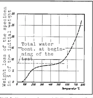
Figure 12 shows the loss of weight of a concrete containing some
calcareous aggregate according to ref.(7). The vigorous liberation of water
between 100 and 300°C is clearly evident. Above 400°C a slight loss of
weight then occurs due to liberation of water from the calcium hydroxide of
the cement paste. At about 600°C the conversion of the limestone begins.
This may be summed up as follows:
The thermal conductivity of concrete is determined primarily by the
bulk density and the moisture content. The greater the bulk density and
structural members is affected decisively by the evaporation of the free and bound water.
2.3 Steel
The fire resistance of all reinforced concrete constructions,
including steel concrete and prestressed concrete, is decisively affected by
the behaviour of the reinforcement. The change in the mechanical properties
of steel on exposure to high temperatures depends on the kind of steel and
especially on the carbon content. In the following paragraphs a number of
typical examples are cited inasmuch as these are required for an understanding of the behaviour of reinforced concrete constructions.
2.31 Thermal expansion
In Figure 13 the linear thermal expansion of a steel with 0.4% carbon
is plotted after ref.(24). It will be recognized that the thermal expansion
is continuous up to temperatures of about 700°C. The coefficient of thermal
expansion increases slightly. Compared with the thermal expansion of the
concretes (Figure 5) the expansion of steel is somewhat less than
sand-and-gravel concrete, but somewhat greater than limestone concrete. Generally
speaking, however, the thermal expansion of the steel and the concrete is the
same even over considerable temperature ranges.
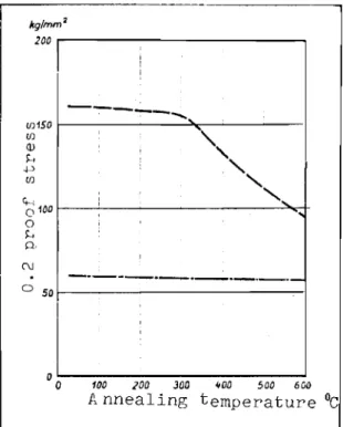
2.32 Yield point at elevated temperatures
Figures 14 and 15 show the yield point (0.2 proof stress) for a
number of steels as a function of the temperature. The hot tensile strength
curves have been left out, because by and large they are closely related to
the yield point curves. Only in the temperature range around 200°C is there
at first a slight rise in the tensile strength.
Figures 14 and 15 differ in that in the former the tests were carried
out in the hot state, while in Figure 15 they took place after cooling. The
values of Figure 14 are important for the behaviour of the material during
a fire, those of Figure 15 for appraising the bearing capacity of a structure
after a fire. Rolled steels in general recover their original strength on
cooling, whereas cold-forged steels lose some of their strength.
0.11
slightly with increasing temperature, but then more rapidly. At 500 to
o
600 C the design stresses calculated in the construction are attained. Contrary to a widespread misconception, the yield point of high quality prestressed rods is not below that of ordinary reinforcement rods. It is only in the temperature range of around 600°C that all the values more or less coincide.
2.33 Rupture strain
Figure 16 shows the change in rupture strain of a mild steel under
the influence of elevated temperatures, after ref. (27). Up to 200°C the
rupture strain at first decreases rapidly, but then in the region of higher
temperatures it increases just as rapidly. At 600°C the failure strain is
about twice as great as at 20°C.
2.34 Modulus of elasticity
Figure 17 shows the change in the modulus of elasticity of a
non-siliceous S. M. mild steel as a function of the temperature. The behaviour
of other steels is similar. It is clear from Figure 17 that the modulus
of the steel drops to about half its value at room temperature between 500
and 600°C. The decrease, therefore, is not as great as in concrete.
2.35 Thermal Conductivity and specific heat
The thermal conductivity of the steels normally used in construction
decreases with increasing temperature. Figure 8 shows the heat transfer
coefficient of pure iron and of structural steel with 0.8% carbon content.
The values for most structural steels lie within the hatched area. It must
be realized that at comparatively low temperatures, i.e. at the beginning of
a fire, the heat transfer coefficients of steel are 30 to 50 times as great as
that of concrete. This fact affects the behaviour of very heavily reinforced
structural members in the fire.
The specific heat of iron and steel increases with increasing
temperature. At room temperature the specific heat is approximately c
kcal
kg
.uc
and at 800°C it is 0.2 kcalkg.oC
2.4 Other materials
pre-fabricated concrete parts are used, a number of other materials besides concrete and steel may be employed in the finished structure, e.g. as
bonding 。セ・ョエウL veneers, plasters or for sealing purposes. These materials
include, for example, gypsum products, wood or wooden wares, and plastics. In what follows we shall briefly outline the most important prop0rties of such materials with respect to fire.
Gypsum, as is known, hardens by hydration of the semihydrate or of
the anhydrate to the dihydrate form. When gypsum is exposed to higher
temperatures, some water is given off between 100 and 160°C and complete
dehydration to anhydrate occurs at about 200°C. For this, considerable
quantities of heat are consumed. Hence the heating of all constructions
made of gypsum is greatly delayed at approximately 100°C. Use can be made
of this fact at times, when rapid heating of a building element must be avoided.
However, after dehydration the gypsum loses much of its strength. Moreover, with gypsum plasters under very gas-tight floors the steam
pressure may become so great that the entire plaster breaks away from the ceiling.
Wood occurs in concrete structures, e.g. in the form of small
structural parts such as dowels, or the like. Wooden laths are also embedded
in the concrete in the manufacture of certain concrete products with a view
to securing projecting sections. Wooden parts surrounded by concrete on
several sides do not ignite as easily as completely exposed ones, owing to
their poor contact with the atmospheric oxygen. In addition, larger
cross-sections always have a higher resistance to fire than delicate, thin
structural parts. Caution is always required whenever parts of the whole
construction which are essential for fire protection are secured to wooden
parts. A critical temperature for the ignition of wood can only be stated
approximately, since it varies greatly with the kind of wood, its moisture content, the atmospheric oxygen available, the surface texture and other
factors. Under unfavourable conditions, however, ignition may be expected
at 250 to 300°C. Some times, even lower ignition temperatures have been
noted.
Ceiling fillers or slabs of mineralized wood wool have been found
excellent in conjunction with concrete. The resistance of thin steel
re-inforced concrete ribbed ceilings to fire can be greatly improved by the use of these parts, since even in a fully raging fire they ash slowly, and thus constitute good
ゥョウオャ。エゥッョHRYLセQIN
critical temperature for all plastics can be stated. Some plastics alter
their properties even at lower temperatures than wood. Especially in the
field of prefabrication, where plastics are popular as binding agents, ad-hesives or joint seals, therefore, fireproof requirements must be taken into account in the planning stage, because subsequent changes are frequently very difficult to carry out.
3.
The Behaviour of Concrete and Steel-Reinforced Concrete Members in Fires3.1 General
A knowledge of the change of properties of building materials will
suggest important ideas concerning the behaviour of structures in fire. The
fire test on the whole structural part, however, is decisive in appraising
fire resistive quality. In many countries there are standards for conducting
fire tests. These regulations are alike in principle, although, they differ
from each other in detail.
Basically, it is laid down that the structural part to be
investiga-ted must be exposed to damaging fire(30), i.e. a fully developed conflagration.
In order to get comparable test results it is customary to represent the
development of an idealized fire by temperature-time curves. Figure 19
shows the temperature-time curves used in various countries. It will be
noted that all the curves are very similar to each other, so that the results on constructions investigated by the standards of various countries on the
whole are comparable with respect to temperature load. In order to get the
best possible agreement, a uniform curve has been drawn by ISO, which fits
the previous curves well. However, even under earlier conditions, differences
in the results from fire tests in different countries have been due less to different temperature loads than to differences in test material and other test conditions.
In attempting to analyse the curves represented in Figure 19 it must first be realized that in the first half hour, at the start of the fire, the temperatures in the fire compartment rise very rapidly, and then increase more
slowly. The rapid changes of temperature at the beginning of a fire in
general result in large temperature differences in the structural member. At
an early stage, therefore, considerable deformations or stresses occur. As
the fire continues, there is a continuously progressive, but more even
heating of the construction, which, unless a temperature equilibrium sets in
before hand, can result in failure. The uniform temperature-time curves
This is important, because for the most part the temperatures lie below
the 12000C limit. At this temperature, however, decomposition or
de-struction of a number of mineral building materials occurs. Several
kinds of natural stones, for example, decompose. Many light-weight
concretes, which show excellent behaviour in fire up to about 12000C owing
to their good thermal insulation properties, are destroyed when the
temperatures go higher than this. Of course, such conditions would occur
only in rare and exceptional cases.
In the course of a fire the structural parts ought to perform their
functions. Essentially, these are as follows:
a) Bearing parts, such as beams, columns, ceilings, etc. must retain their bearing strength and stability.
b) Space separating parts must continue to be effective in separating space, i.e. they should not afford a passage for the fire.
Basically, two cases must be considered in the testing of structural
members for their resistance to fire. On the one hand, the structures may
be tested to failure, i.e. until they no longer satisfy the above functions
a or b, as the case may be, or a time test may be made, i.e. it is determined whether the functions will continue to be performed during a predetermined time.
In order to be able to estimate whether and how long the bearing capacity of a structure will remain intact in a fire, the resistance of
bearing structural parts to fire is tested under load. There is little
difference in the regulations on this point from country to country. In
general, however, the simple calculated permissible load is applied in the
fire test. Since fire is a catastrophic occurrence, a safety factor of one
is regarded as adequate as far as bearing capacity is concerned.
The stability is threatened by severe deformations. For example,
in the case of walls exposed to the fire, on one side, the resulting de-flection may produce such great eccentricity that the wall will collapse.
Space separating structural members must not allow the fire to pass. That is to say, no hot gases should seep through, and the temperatures on
the side away from the fire must not rise above a certain value. The
critical rise in temperature in most countries today is put at an average of about 140°C above the initial temperature, and at individual points up
to 180°C is allowed. The reason for this requirement is to prevent easily
ignitable material, which may by chance be stored on the unexposed side of the space separating members, from igniting, for otherwise the fire will
jump the barrier.
In a number of countries some relaxation of these rules is allowed for certain members, e.g. doors, parapets, or walls of glass blocks.
Special demands are made of chimneys and roofing materials.
The duration of the fire test depends on the type of structure in
which the test member is to be used. Requirements differ greatly in the
various countries. In Germany for buildings threatened with fire,
"fire-resistant", and in exceptional cases "highly fire-resistant" construction
is reqIJired. "Fire-resistant" members, according to DIN 4102 must continue
to perform their functions in the fire tests for 1 1/2 hours, and "highly
fire-resistant" must do so for 3 hours. In other countries, for certain
buildings such as warehouses, which are particularly exposed to fire hazards, still longer resistance times are prescribed.
Increasing the demands for duration of resistance against fire beyond a certain time does not always require substantial changes in the
construction. This is because for many structural members there is a
certain time at Which, during the standardized fire test, heat equilibrium
is more or less attained. In this state the heat losses on the side away
from the fire are approximately equal to the input of heat on the side
towards the fire. If the structure has not collapsed by this time its
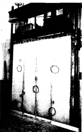
resistance of fire can be greatly increased by reaching this threshold. To carry out the fire test, the structural member to be tested is
installed in a fire test chamber, and, if it is a bearing ュ・ュ「・セ is subjected
to a load. Figure 20 shows a fire test chamber with a loading apparatus
for walls. The wall is prepared for testing. Figure 21 shows,
semi-schematically, a fire test chamber for ceiling constructions. Today the
testing institutions of many countries have very modern fire test chambers with partially or fully automatic control.
The test member is installed in the fire test chamber in a manner that simulates as closely as possible the incorporation of the member in practice.
3.2 Walls of light weight and heavy concrete
3.21 Heating
Concrete walls can be manufactured either monolithically from heavy
or ャゥセィエ weight concrete, or may consist of slabs of considerable size or of
walls. The former have both bearing and space separating functions,
where-as the latter operate only where-as space dividers. In general, thick walls of
the kind required for outside walls in tall building constructions, due to
thermal insulation considerations are not endangered by fire. In the case of
thin walls, however, there is a possibility that the permissible rise in temperature on the side away from the fire may be exceeded.
Figure 22 shows the necessary thickness for massive walls of heavy
and light weight concrete as a function of the test time, so that no
in-crease of temperature セイ・。エ・イ than 140 0
c
above the initial temperature willoccur on the unexposed side. In the case of walls with cavities, the
deciding factor is the thickness of solid material. The fire resistance
time F increases exponentially with the wall thickness d, approximately
according to the function F
=
d l.7 ( 3
1).The critical increase of temperature on the side away from the fire
up to test times of 3 hours is only important, generally speaking, in the
case of heavy concretes and wall thicknesses of d < 15 cm. A few kinds of
hollow blocks made of heavy concrete constitute an exception to this. As
in the case of hollow blocks of other materials, in unfavourable cases it can happen that the shells on the side of the fire will burst after a
certain time and that cracks will form through the entire block as the test
continues. The permissible rise in temperature for light-weight concretes
is seldom exceeded, even in the case of thin walls.
For masonry brick walls or slab walls, careful design and execution
of the joints is extremely important. Grouting or smoothing of the joints
may help, so as to ensure that no hot gases can penetrate through any gaps
in the joints. Especially where thin plates are employed, the joints have
to be profiled as far as possible, so that adjoining plates fit together in tongue and groove fashion.
The thermal insulation of the structural members during a fire is
greatly affected by the moisture content. First of all, considerable
quantities of heat are needed for the evaporation of the excess water,
which quantities, of course are liberated again during condensation. Thus
structural members with high moisture content rise rapidly to lOOoe, but
only slowly go above lOOoe. In the case of concrete separating members,
such as walls and ceilings, lags ゥセ the temperature rise are observed on
the side away from the fire generally for temperatures between 80 0 and
1000e. Moisture often penetrates in the form of water of condensation
during a fire at joints and hairline cracks. The temperature of these moist
of a heavy concrete wall with a bulk density of about 2400 kg/m3
, a
difference of 1% by weight in moisture content results in temperature differences of about 25°C on the unexposed surface, after all moisture has evaporated.
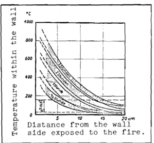
In Figure 23 the temperature curve in heavy concrete walls is represented as a function of the wall thickness, and in Figure 24 the same
curve is shown for a 15 em-thick wall of aerated concrete. The two
diagrams are indicative only, since the scatters and temperature measurements inside the walls are very great owing to differences in moisture content,
aggregates and bulk densities. The delay in heating at 100°C is definite
in the case of the aerated concrete wall, as is also a change in thermal conductivity above and below 100°C.
Numerous compilations about fire tests on walls are available in
the literature. Table II contains a selection of a few typical walls.
Figure 25 shows a wall of slag concrete blocks after a 3-hour fire test.
3.22 Deformations and stability
When exposed to fire on one side, walls tend to bulge more or less
extensively towards the fire side. After the fire, the bulging generally
recedes, and the bulge may even appear on the other side. The magnitude of
the bulging depends on the material, the wall thickness, and above all on the
height of the wall. The mean bulging of unfixed walls can be estimated
approximately by the following equation
f - C h 2 (Tl - T2)
-
8d
where C - material constant f - deflection h - height of wallT - temperature on the side towards the fire
1
T - temperature on the side away from the fire
2
From this equation the important fact is realized that under other-wise equal conditions the bulging increases with the square of the height
of the wall. In Figure 26 the conditions are represented for two walls
which are similar except for their height. One wall is twice as high as the
other. The bulging on one side, however, is four times as great. This must
i-mens 2 m to
3
m high, i.e. the usual height of a storey. In the case oftaller walls, which indeed are rare, but which do exist ョッョ・エィ・ャ・セウL the
effect of the greater bulging in fire should be taken into account, because stability may no longer be guaranteed owing to large eccentricity.
Figure 27 shows the bulges in two walls during fire tests.
Besides lateral bending, gaps may occur in the joints at the margins
owing to bulging of the walls. Therefore, good 'connection between the wall
and the adjacent structural members must be assured in the design.
3.3
Floor structures3.31
Massive, steel reinforced concrete slabsWhereas walls are predominantly compressively stressed, steel-reinforced concrete floors as a rule are sUbject to bending stress. Generally speaking, in floors of tall buildings there is tension on the
underside of the slab and compression on the upper side. In a fire, a
ceiling above the burning area is rapidly heated on the underside. Owing
to the relatively poor heat conduction of concrete the steel reinforcement situated close to the underside in the tensile zone is heated more rapidly to the critical temperatures of steel than is the concrete on the upper
side of the floor structure heated to its critical temperature. Therefore
the heating of the steel reinforcement plays a decisive role in the resistance of steel reinforced concrete floors to fire.
The time during which a steel reinforced slab resists the fire is determined substantially by the following factors:
a) existing steel stress b) steel covering
c) nature and thickness of lining underneath d) quality of concrete
e) thickness of the floor
f) moisture content of the concrete g) kind of aggregate
h) positioning of the slab (restraint)
Figures 14 and 29 show clearly that reducing the steel stress, or in other words over-reinforcing, increases the length of time of the resistance.
By increasing the covering of the steel, the heating rate of the steel reinforcement is reduced and thus the resistance of the steel
re-inforced concrete slab to fire is increased. For a slight increase in the steel covering, for example from I to 2 cm, the increase in the time of
fire resistance, to be sure, is not very great. The reason is evident
from Figure 28. It can be recognized that in the side of a wall or ceiling
nearest the fire there is a very steep temperature gradient, which becomes
flatter towards the inside. That is to say, the temperature difference
between the underside of the floor exposed to the fire and the depth of I cm
is greater than between I cm and 2 cm depth from the surface. A substantial
increase in the time before fracture is obtained only with still greater
steel covprings. Plasters in earlier tests showed greater protective
effect than corresponding increases in steel covering. An essential
condition, however, is that the plaster adheres well. The explanation may
be sought in the fact that plaster has a lower bulk density than concrete
and thus shows greater thermal insulating properties. As a consequence the
temperature gradient in the vicinity of the concrete ceiling surface on the
side of the fire is steeper than that in Figure 28. Moreover, heat
conduction is hindered by the transition between different layers. On the
debit side it may be said that in practice plasters are frequently applied in thinner coats than contemplated in the design and that green plasters with
high moisture content are quickly stripped off in a fire. This is especially
true if the underside of the concrete is smooth. Since the test described
in ref. (25) was made, concrete technology has advanced. Today, in general
more compact concretes are produced. It is therefore easy to understand
that in more recent fire tests the favourable effects of plasters are not always evident, since the plasters have been detached from the concrete at an
early stage in the fire. Priority should be given to this problem in the
future, since in prefabricated structures traditional plasters may be used
less than before, for other reasons as well.
For a number of years special coatings, e.g. of asbestos,
vermiculite and perlite bases, have been used to increase fire protection. With these coatings, even comparatively thin ones, the heat insulation can be so greatly improved that the fire resistance time is increased to many
times that of the uncoated floors. fゥセオイ・
29
gives two examples showingthe effect of coatings on the heating rate of the steel reinforcement rods
and hence on the fire resistance time of reinforced concrete floors. The
curves may be designated as follows:
Curve I - uncoated steel reinforced concrete floors (covering depth
Curve 2 - the same construction, but with a lime-cement plaster 1.5 cm thick;
Curve
3 -
the same construction, but with a cement-lime-vermiculite」ッ。エゥョセ 1.5 cm thick.
The effect of concrete quality on the fire resistance time has not
yet been fully clarified. In earlier tests it was established that for
poor and medium quality concrete up to approximately B 300 the ability of a steel reinforced concrete floor to resist fire increased somewhat with
increasing concrete grades. These results, in more recent tests, which
were not always confirmed are somewhat surprising, since the bulk density and the thermal conductivity of the concrete in general increases with
increasing grade. Perhaps the explanation is that with the increase in
concrete grade the modulus of elasticity also increases. Given equal
thickness and reinforcement the floor, however, a higher modulus of
elasticity of the concrete means a lower steel stress. In going from a B 160
to a B 300 the modulus of elasticity increases by approximately 50%. This
displaces the neutral axis of the cross-section upwards, and, for a concrete floor 12 cm thick with an average reinforcement component, causes a drop in
steel stressing of about
6
to 10% (Figure 30). With an unplastered ceilingthis corresponds to an extension of the fire resistance time by about 10
minutes. However, these findings for comparatively low grades of concrete
must not be applied to higher grades, because here the modulus of elasticity does not increase greatly, and secondly very compact concretes do not be-have at all favourably in fires, and under the most unfavourable conditions tend to spall.
The considerable effect of the thickness of the floor on the
fire-resistance time is represented in Figure 31. This relates to concrete slabs
reinforced with comparable steel rods. Aside from the fact that
comparatively large cross-sections behave more favourably in fire owing to their greater heat capacity, it may also be assumed here that despite mathematically equal calculated steel stress, the actual steel stress in
a thicker floor is less. Another favourable result is that the changes of
form of a thick floor are comparatively less than those of the thinner one. Moreover, it should be borne in mind that under otherwise equal conditions, the moisture content of a thicker member is generally greater and hence
it takes longer to heat through. As will be shown later, the fire resistance
times in other structural members, also, are increased by increasing the
31 minutes 41 minutes
65 minutes
2 hours
of special importance in practice, because in Germany almost all relatively extensive series of fire test have been carried out on steel reinforced
concrete floors of thicknesses less than 10 cm. The values obtained formed
the basis for the pertinent regulations. However, for the thicker floors
now being used predominantly in practice, these values are much too
unfavou-rable. This gain may be particularly important especially in prefabricated
construction, where for a great variety of reasons plastering on the
under-side of steel reinforced concrete floors is not possible. A fire-resistance
time of 90 min ("fire resistant") is readily attainable with floor
thick-nesses of about 15 cm, increasing the steel covering from 1 to 2 - 3 cm.
The static system also influences the bearing capacity of a floor in
a fire. Continuous slabs are more favourable than single bay slabs. In
the case of continuous slabs, before failure of the strongly heated horizon-tal reinforcement, at first the still relatively cool upper column
reinforce-ments act with increased stresses as cantilevering reinforcement. As a
consequence there is a relieving of the stresses in the bay reinforcements. Collapse does not occur until the yield point is exceeded in lower and
upper reinforcements. From a fireproofing point of view, therefore, a
continuous upper reinforcement throughout the bay is especially favourable. The behaviour of single-bay slabs fixed at all sides has not yet
been fully clarified(3 4
, 67 ) .
Table III gives a summary of the increases of fire-resistance time as a result of the above-mentioned measures.
Besides these possibilities, the resistance of massive
steel-reinforced concrete slabs can also be affected by the choice of aggregates. To be sure, the available data do not provide a uniform picture, since
obviously other factors, for example, moisture content at the time of the
test, the restraint of the slabs in the experiment, etc., have a very
strong influence on the test results. According to Davey and AShton(34),
concrete floors of similar nature but made with different aggregates had the following fire resistance times:
Flint Dolerith Basalt
3.32
Prefabricated floors3.321
Fire-resistance timeIn recent years prefabricated floors have been very widely used. Among these a few basic types may be singled out from the very large number of systems found on the market.
1. Beam floors with intermediate structural members.
2. Ribbed floors with intermediate bearing members or compressed
slabs of poured-in-place concrete.
3.
Floors consisting of beams or planks laid side by side.4.
Prefabric2ted slab floors.The behaviour of pr-ef abr-Lc ate d floors in fl i-e Lr: principle is
similar to that of solid slabs. Since the steel reinforcements are
frequent-ly better protected than irl solid slabs, in many cases a longer
fire-resist-ance time may be expected than solid slabs of equal thickness.
Accordingly the measures indicated under point no.
3.31
for solidslabs for improving the fire-resistance time hold also for prefabricated
floors. Investigations have shown that almost all non-prestressed reinforced
concrete floors which were given a coating of lime-cement 1 1/2 cm thick on
the underside survive the required test time of 1 1/2 hours in the fire
test according to German regulations.
In Table IV, examples of typical prefabricated floors are given with
the corresponding test results. For comparison, the results of a few solid
floor slabs are also listed.
3.322
DeformationsBesides bearing capacity, changes of shape in the course of a fire
are also important in the behaviour of prefabricated floors. Directly
after the start of fire exposure, floors exposed to the fire begin to change
their shape. As a rule they bend toward the fire, i.e. they begin to sag
downward. Figure
32
shows the deflections of some of the prefabricatedfloors listed in Table IV. The value of the deflection depends not only
on the span and thickness of the floor, but also on the construction and
the material. For examole, hollow beams of heavy concrete or solid
light-weight concrete slabs bend somewhat more than solid heavy concrete slabs under similar conditions.
side, we warlted to know how they would behave in the presence of fire under
partial ャッ。、ゥョセN If the deformation of loaded parts of a floor compared
with that of the unloaded parts, there is a danger of shearing at the
senaration joints and the fire breaking through. A number of floors were
therefore ゥョカ・ウエゥセ。エ・、 in fires, only half of which were loaded on one side
with the calculated permissible loads(43). All the floors (floors without
transverse reinforcement and with relatively large deflection were deliber-ately chosen for the test) resisted the fire under these conditions and the
fire did not break through. In addition, small floor units of aerated
concrete were tested in unloaded and loaded conditions. As is evident from
Figure 33, the results showed that the deflections were almost the same at
the beginning of the fire test. This means that the initial deflection
depended entirely on the temperature difference between upper and lower
sides. Only after exposure to the fire for over 20 minutes did the
deflec-tion of the loaded floor begin to increase more strongly than that of the
unloaded. At this time a gradual reduction of the modulus of elasticity
began. Even at this time, however, the deflection component due to
temper-ature differences remained relatively large compared with that due to the loading.
In certain exceptional cases, floors are deflected at the start of
a fire not towards the fire, but away from it. This happens, for example,
if the ribs of a ribbed floor are heavily insulated in order to protect the steel from heating, and the upper compressed slab heats up more rapidly than
the ribs. On the other hand, a permanent upward deflection after the
termi-nation of a fire is comparatively frequent. This occurs, for example, with
some aerated concrete floors. As a result of fire exposure the concrete
after cooling undergoes a slight, permanent increase of volume, while the
steel reinforcements revert to their original length. The result is a
"pre-stressing" effect which causes an upward curvature.
3.323 Downward propagation of fire
Generally speaking, fire tests are carried out under the obvious assumption that fire spreads upward from below, i.e. floors above the fire
are mainly endangered. Sometimes, however, we are interested in the
behaviour of floors where the fire is propagated downward. For this purpose,
tests were made with a partial prefabricated floor of steel reinforced
hollow planks laid side by side(44). The same floor had already been tested
remained intact under fire exposure from above during the test time of
1 1/2 hours. The permanent deflection of the floor after the fire was
greater than in the regular tests. Figure 34 shows the upper side of a
concrete plank of the test floor after the fire.
3.324 Prefabricated slab floors
In the prefabricated, large-area steel reinforced concrete floors, which have very recently come into use in apartment houses and in industrial construction, it is often not possible to apply a plaster to the underside
of the floor during the prefabrication process. Subsequent plastering may
nullify the economy of this method of construction. Under these
circum-stances the fire-resistance time can be increased by the following measures:
1. By decreasing the reinforcement stress
2. By increasing the reinforcement covering
3.
By the use of suitable aggregatesII. By incorporation of an ancillary layer of lightweight concrete
with low thermal conductivity
5.
By incorporation of slabs of heat-insulating materials eitherin the concreting stage, or subsequently, over the finished and installed ceiling.
Simply increasing the reinforcement covering is of limited value. An unplastered high-grade concrete floor sometimes fails because one or more pieces of the concrete surface spall off and at these points the steel
re-inforcements rapidly become heated. Structural measures should therefore
be taken, e.g. by incorporation of a light wire mesh, to ensure that spalled
portions cannot falloff. At the very high エ・セー・イ。エオイ・ウ occurring in a fire,
heat transfer takes place primarily by radiation, and therefore particles of concrete that have loosened but do not fall still provide adequate protection for the steel reinforcements.
Ancillary layers are made mainly of lightweight concrete or from
slabs of other heat-insulating materials. The required fire protection has
also been attained in prefabricated concrete slabs simply with the aid of gypsum boards or cement-bound wood-wool lightweight boards which are merely concreted over (cf. Table IV, no. 2).
3.4 Prefabricated steel reinforced concrete steps
Steps constitute a special case of the ;'floor structure". Opinions
differ as to whether the behaviour of steps in a fire must meet the same
requirements as floors, i.e. whether they must remain effective as space
separators and at the same time retain their bearing capacity, or whether
only the latter is important. At the present time German regulations
require both specifications to be met. However, an amendment may be
ex-pected.
Prefabricated steps are generally produced in the following struc-tural forms:
1. Large plates with steps mounted on them
2. Beams placed side by side
3. Side walls with steps placed between them
4. Beams with steps mounted on them
Basically the same considerations apply from a fire standpoint for
steps as for floors. Figure 35 shows examples of two designs which can be
regarded as "fire-resistant" according to the existing German regulations,
i.e. they have a fire resistance-time of more than 1 1/2 hours(45,46).
3.5 Steel reinforced concrete beams
Test results on the behaviour of steel reinforced concrete beams in
fire are available from various countries(25,34,47). In some instances
T-beams, and in others beams of rectangular cross-section, have been
in-vestigated. From these tests it may be assumed that the behaviour of steel
reinforced concrete beams is determined by substantially the same quantities
as thgt of slabs. However, no direct comparison between steel reinforced
slabs and beams is possible, since in the case of beams the ratio of the surface attached by the fire to the cross-section is less favourable than it
is for slabs. On the other hand, in the case of beams the greater structural
height is a positive factor.
The effect of the steel covering has been investigated in
consi-derable detail. In the case of beams, it was again found that the
fire-resistance time did indeed increase with increasing cover, but not
pro-portionally to the thickness of the covering. Figure 36 shows the effect of
steel reinforcement covering on the fire-resistance time. In all the tests,
which owing to the different sizes of beams and different bearing arrange-ments are not directly comparable, it was clearly evident that the increase
of fire-resistance time is less than the increase of steel reinforcement cover.
The age of the member influence the fire-resistance time of T-beams
more definitely than plates(25). In Figure 37 the effect of age is
repre-sented. Presumably the increase of fire-resistance time with increasing
age can be attributed to a simultaneous increase of the quality of the concrete and the modulus of elasticity.
As in the case of slabs, an increase of fire-resistance time can
also be obtained by a suitable choice of aggregates(3
4) .
Three beams wereproduced which differ only with respect to the kind of aggregates employed.
Figure 38 shows the 」イッウウセ・」エゥッョ of the beams; the test results are
contain-ed in Table V.
In considering the earlier test results on beams it should be mentioned that the beams were made of relatively low-strength concretes. Nowadays higher grade concretes are generally employed, especially in the
manufacture of prefabricated steel reinforced beams. With structural
members of high quality concretes there is a danger of the explosive spalling
of pieces of concrete from the surface. If parts of the beam
reinforce-ments are thus exposed, rapid failure occurs. It is assumed that this
spalling is caused by water vapour over pressure due to evaporation of the
water present in the concrete. This view is supported by the fact that such
spalling occurs predominantly in green and very high quality, i.e. very compact concretes, shortly after the start of exposure to the fire.
Probably other influebces also contribute to the tendency of concrete to
spall in fire. For example, an influence of the aggregates cannot be ruled
out. Probably this has more to do with intrinsic porosity than with the
kind of material involved. For example, spalling was observed in very
moist mortars made of lightweight aggregates. This may be due to the fact
that on rapid heating moisture stored in the aggregate cannot escape rapidly enough through the more compact cement paste.
It is probable also that the tendency to spall is influenced by the
design of the cross-section and by the mechanical stress during the fire. A
preference towards spalling is noted, for example, in the slender stems of
I-beams and on the under sides of the cross slabs of T-beams. In these
members strong heating produces very high compressive stresses owing to the inhibited expansion, and these stresses cannot be absorbed even by concretes
of very high strength. More precise investigations should be carried out
certainly does not occur on all occasions.
3.6 Columns
3.61 steel reinforced concrete columns
Whereas in steel reinforced concrete beams and floors the reinforce-ments are generally subjected to tensile stress, in the case of reinforced
concrete columns the steel is stressed in compression. The compressive
strength of steel, i.e. the compressive yield point, is also reduced under the influence of high temperatures, so that in the presence of fire there is a greater danger of buckling.
In earlier years, extensive series of fire tests were carried out
cTXMセoI
on steel reinforced concrete columns ) . The fundamental tests of
Ingberg and his co-workers are still indicative. At that time concrete
quality grades were still comparatively low, the column cross-sections were
large and the reinforcement ratios were low. Very high fire-resistance times
were attained with plastered columns where the plaster was furnished with a light wire-mesh inlay, which prevented the plaster from dropping off in the course of the fire.
More recently there has been a strong tendency in construction
towards reducing the dimensions of individual structural members. In
par-ticular, architects have been calling for ever slenderer columns in fafade. This has meant the employment of higher concrete grades and larger pro-portions of reinforcement.
With the advance of prefabricated construction a desire has arisen to use uncoated columns with high fire-resistance time, since subsequent coating tends to nUllify the economic advantages of prefabricated
construc-tion. Therefore, new series of fire tests have been conducted recently at
various places with slender uncoated, and in some cases heavily reinforced
columns
C34,Sl-SS).
In addition to depending on the cross-section size, the resistance of a steel reinforced concrete column is influenced primarily by effectiveness
of the covering over the steel. Owing to the severe compressive stresses in
the boundary zone, this covering is more severely stressed at the beginning
of the fire in columns than in other structural members. If the concrete
or coating falls off prematurely, then even thick columns will not attain
long fire-resistance times. The most important measures for raising the
covering, whether of concrete or plaster, in place while it is being
attacked by the fire. This is best done by inlaying a light wire mesh
between the reinforcement and the surface of the concrete. When this is
done, constant heating of the column, and hence a more even course of the
fire test, is obtained. The following observation may be made in here. With
the use of certain aggregate materials, e.g. limestone or blast furnace
slag fragments, the concrete covering is less liable to falloff. In such
cases, the wire mesh inlay can sometimes be dispensed with.
The bearing capacity of a compressively stressed column is described approximately by the following addition law:
p
collapse = Kb . Fb + 0st . Fe
where: K
b cube strength of the concrete
Fb cross section of the concrete
ost = tensile yield limit of the steel
F = steel cross-section
e
In principle these conditions also apply in the course of heating, taking into account, obviously, the altered properties of the material. From the equation the following conclusions may be drawn:
With increasing concrete cross-section, given to equal reinforcement ratio, the fire-resistance time has increased, because complete heating of a larger cross-section up to the critical temperatures must take longer.
However, increasing the reinforcement percentage, i.e. increasing Fe' under otherwise similar conditions has not so great an opposite effect, since the steel reinforcements of a heavily reinforced column heat up just about as quickly to the critical temperature as they do in a lightly 're-inforced column.
The time until failure is also influenced by the size of the
applied load. No data are available on the influence of the degree of
restraint and the slenderness on the fire-resistance time. It can, however,
be assumed that the test results would be greatly influenced.
Figure
9
shows the results of recent fire tests with prefabricatedcolumns carried out under the auspices of the Federal Association of the
Concrete Block Industry(53). In this, columns 3.60 m long with the following
cross-sections were tested:
F 15 cm x 20 cm = 300 cm2
F 20 cm x 20 cm = 400 cm2
F 24 cm x 30 cm 720 cm2
For some of the columns limestone was used as the aggregate, and
for others a quartzitic material. Figure 40 shows the column cross-sections.
Figure 41 shows a column after the fire test and the quenching water test. The inlaid wire mesh is clearly shown.
Figure 39 shows a definite increase of the fire-resistance time
with increasing concrete cross-section. Striking, however, is the excellent
behaviour of thin columns, especially when limestone is used as the
aggregate. British fire tests showed a similar result on somewhat shorter
columns, and some of these are plotted in Figure 39 as well(34). In
Figure 42 the results of the fire tests of the columns represented in
Figure 40 are compared with the results of more recent French fire tests(52).
Since in the latter the test arrangement (column length 2.30 m) differed,
the results are not directly comparable. Nevertheless it can again be
recognized that the fire-resistance times in the case of a French test, as in the German results, are more or less proportional to the concrete
cross-section. In the French tests the reinforcement ratio セ was
substan-tially decreased with increasing concrete cross-section, so that the applied
load on all columns was equal. Despite the radically altered reinforcement
component, the tendency is the same as in the test with constant reinforce-ment component.
Another successful means of increasing the fire-resistance time of columns was found to be the displacement of a substantial part of the
re-inforcement towards the interior of the column. With heavily loaded spiral
columns, which have a somewhat greater resistance than rectangular columns, fire resistance times of more than 1 1/2 hour were obtained(55).
To sum up, the behaviour of steel reinforced concrete columns in fire may be represented as follows:
1. The most important preventive means is to see that the covering
of the steel does not drop off. A wire mesh inlay will
accomplish this.
2. The choicE of aggregates has a very great influence. Limestone
concrete columns behave better than concretes with quartzitic
。ァァイ・セ。エ・ウN Basalt and blast furnace ウセ。ァウ fall somewhere
between the above-mentioned groups.
3. Under the calculated permissible load columns of larger