HAL Id: cea-01570026
https://hal-cea.archives-ouvertes.fr/cea-01570026
Submitted on 28 Jul 2017
HAL is a multi-disciplinary open access
archive for the deposit and dissemination of
sci-entific research documents, whether they are
pub-lished or not. The documents may come from
teaching and research institutions in France or
abroad, or from public or private research centers.
L’archive ouverte pluridisciplinaire HAL, est
destinée au dépôt et à la diffusion de documents
scientifiques de niveau recherche, publiés ou non,
émanant des établissements d’enseignement et de
recherche français ou étrangers, des laboratoires
publics ou privés.
Design Framework for Reliable Multiple Autonomic
Loops in Smart Environments
Adja Ndeye Sylla, Maxime Louvel, Eric Rutten, Gwenaël Delaval
To cite this version:
Adja Ndeye Sylla, Maxime Louvel, Eric Rutten, Gwenaël Delaval. Design Framework for Reliable
Multiple Autonomic Loops in Smart Environments. 2017 IEEE International Conference on Cloud
and Autonomic Computing (ICCAC), Sep 2017, Tucson, AZ, United States. �cea-01570026�
Design Framework for Reliable Multiple Autonomic
Loops in Smart Environments
Adja Ndeye Sylla, Maxime Louvel
Univ. Grenoble Alpes, CEA, LETI, DACLE, LIALP, F-38000 Grenoble
[email protected], [email protected]
Eric Rutten, Gwenaël Delaval
Univ. Grenoble Alpes, INRIA, CNRS, Grenoble INP, LIG, F-38000 Grenoble [email protected], [email protected]
Abstract—Today’s control systems such as smart environments have the ability to adapt to their environment in order to achieve a set of objectives (e.g., comfort, security and energy savings). This is done by changing their behaviour upon the occurrence of specific events. Building such a system requires to design and implement autonomic loops that collect events and measurements, make decisions and execute the corresponding actions.
The design and the implementation of such loops are made difficult by several factors: the complexity of systems with mul-tiple objectives, the risk of conflicting decisions between mulmul-tiple loops, the inconsistencies that can result from communication errors and hardware failures and the heterogeneity of the devices. In this paper, we propose a design framework for reliable and self-adaptive systems, where multiple autonomic loops can be composed into complex managers, and we consider its application to smart environments. We build upon the proposed framework a generic autonomic loop which combines an automata-based controller that makes correct and coherent decisions, a transac-tional execution mechanism that avoids inconsistencies, and an abstraction layer that hides the heterogeneity of the devices.
We propose patterns for composition of such loops, in parallel, coordinated, and hierarchically, with benefits from the leveraging of automata-based modular constructs, that provides for guar-antees on the correct behaviour of the controlled system. We implement our framework with the transactional middleware LINC, the reactive language Heptagon/BZR and the abstraction framework PUTUTU. A case study in the field of building automation is presented to illustrate the proposed framework.
I. INTRODUCTION
Today’s environments (e.g., buildings) are equipped with numerous devices (i.e., sensors, actuators) that are managed by a set of software entities. The aim is to achieve a set of objectives related for instance to comfort, security and energy savings. Achieving the objectives requires to design and imple-ment autonomic loops that collect events and measureimple-ments, make decisions and execute the corresponding actions.
The design and the implementation of such loops are made difficult by several factors: the heterogeneity of the devices, the risk of conflicting decisions, the inconsistencies that can result from communication errors and hardware failures. An inconsistency occurs when an action is wrongly assumed to be performed. For instance, switching on a lamp and assuming that it is on becomes an inconsistency if the lamp stays off due to a communication error or a failure. In addition, complex realistic adaptive systems (e.g., smart environments) require the combination of multiple autonomic loops. These
autonomic loops need to be designed individually in order to make the design of the system less complex, by separating subsystems and their local objectives. They also need to be built in such a way that they are reliable w.r.t. their design (e.g., by formal verification or synthesis of their behaviour) and their execution (e.g., by transactional mechanisms ensuring runtime consistency). In addition, the way the loops are composed has a strong impact on specification, design and implementation. Hence, loops composition must be done appropriately. Finally, the composed loops require support for coordination.
Several solutions have been proposed for the design and the implementation of single autonomic loop [1], [13], [8], [14]. Solutions for multiple autonomic loops coordination have also been proposed [5], [12], [15], [10], [24], [2], [3]. However, these solutions do not handle the inconsistencies that can result from communication errors and hardware failures.
In this paper, we propose a design framework for reliable and self-adaptive systems, where multiple autonomic loops can be composed, and we consider its application to smart envi-ronments. We build upon this framework a generic autonomic loop, which combines an automata-based controller that makes correct and coherent decisions, a transactional execution mech-anism that avoids inconsistencies, and an abstraction layer that hides the heterogeneity of the devices. Our contributions are:
• Several patterns for the composition of autonomic loops.
These patterns benefit from the leveraging of automata-based modular constructs, that provides for guarantees on the correct behaviour of the controlled system;
• An implementation of our framework with the
transac-tional middleware LINC [17], the reactive language Hep-tagon/BZR [11] and the abstraction framework PUTUTU;
• A case study in the field of building automation.
The paper is structured as follows. Section II gives the background material. Then, Section III presents different pat-terns for autonomic loops composition. Section IV presents autonomic loops adaptation. Section V presents and discusses a case study, in the field of building automation, to validate the framework. Then, Section VI discusses related work. Finally, Section VII concludes the paper and gives future works.
II. BACKGROUND
This section presents a generic control loop for smart environments, its design and its implementation.
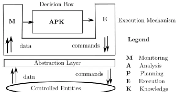
Abstraction Layer Controlled Entities Decision Box APK M E Legend M Monitoring A Analysis P Planning E Execution K Knowledge data Execution Mechanism data commands commands
Figure 1: Generic control loop for smart environments
A. Generic control loop for smart environments
In a smart environment, it is required to continuously 1) collect data through sensors;
2) analyse the data to make decisions; 3) apply the decisions through actuators.
This can be done by a MAPE-K [16] based control loop as illustrated in Figure 1. This control loop consists of
• An abstraction layer that allows to communicate with
the sensors and the actuators and hide their heterogeneity;
• An execution mechanism that collects data from the
sensors and executes commands through the actuators;
• A decision box that analyses the data and computes
commands based on knowledge about the environment. This generic control loop can be implemented using a mid-dleware for the Internet of Things or smart environments [20]. B. Middleware Support With LINC
The control loop presented in Figure 1 can be implemented using the middleware LINC [17]. This middleware provides:
• A rule based language and an execution environment;
• An abstraction framework, called PUTUTU [19], that
enables the communication with sensors and actuators.
1) LINC Middleware: language and abstraction framework
a) LINC language: It is based on three paradigms
• Associative Memory [6]: It consists in modelling the
considered application as a set of distributed tuple spaces containing tuples. In LINC, tuple spaces are called bags and are grouped according to the application logic, in objects. Tuples are used to model the entities of the application (e.g., a lamp and its state) and are manipulated using three operations: rd, get and put. The rd is used to verify the presence of a tuple in a bag. The get is used to remove a tuple from a bag and the put is used to insert a tuple. These operations are used in production rules.
• Production Rules [7]: A production rule consists of two
parts: a precondition and a performance. In the precondi-tion, the operation rd is used, with a partially instantiated tuple as parameter, to verify specific conditions in the system (e.g., presence detected). If these conditions are true, the performance is triggered. The performance uses the three operations. The rd is used to verify conditions. The get and the put are used to perform actions on the system and update its logical state (i.e., tuples in bags).
PUTUTU Framework
EnOcean Object_dongles_modules Object_wsan_sensors Object_wsan_actuators
Object_wsan_sensors_actuators
Watteco TelosB Homes
PLUGWISE LON EnOcean
Tellstick
Figure 2: PUTUTU objects
• Distributed Transactions [4]: They are used in the
per-formance part of a production rule. A transaction allows to group as one operation the verification of conditions (rd), the realisation of actions (put), and the update of the system logical state (get and put). The performance part of a rule may abort if, for instance, the verification of a condition through a rd operation is no longer true. The performance also aborts if a put operation fails because the corresponding action (e.g., switch on a lamp) cannot be performed for some reason (e.g., actuator failure).
b) LINC abstraction framework: PUTUTU [19], as
il-lustrated in Figure 2, consists of a set of LINC objects (e.g., HOMES, LON) that inherit from four generic LINC objects:
• Object_dongles_modules: It is used to manage a dongle
or any other equipment plugged in an ethernet or a USB port. The dongle allows to communicate with the sensors and/or the actuators of a specific technology. It has two bags: Type and Location. Type associates the id of a sensor (resp. an actuator) to its type. Location associates the id of a sensor (resp. an actuator) to its location.
• Object_wsan_sensors: It is used to manage sensors. It
has one additional bag called Sensors which associates the id of a sensor to its latest measured value. This bag contains tuples in the format (id, value). Hence, the value measured by any sensor of any technology is read by applying the operation rd(id, value) on a Sensors bag.
• Object_wsan_actuators: It is used to manage actuators.
It has one additional bag called Actuators which is used to send commands to actuators. The tuples of this bag are in the format (id, command, parameters). The insertion of such a tuple in an Actuators bag, using the operation put, actually sends the command to the specified actuator.
• Object_wsan_sensors_actuators: It is used to manage
technologies providing both sensors and actuators (e.g., EnOcean, LON). This object is derived from the two previous generic objects and inherits from their bags.
c) Example of LINC rule: Listing 1 presents an example
of LINC rule. This rule is a decision box that switches on the two lamps of a room when a presence is detected. The precondition of the rule (before the symbol ::) first verifies if both lamps (lamp12 and lamp13) of the room are off (lines 1, 2). This is done by applying two rd operations on the States bag of the object Room. Then, the precondition
1 [ " Room" , " S t a t e s " ] .r d ( " lamp12" , " o f f " ) &
[ " Room" , " S t a t e s " ] .r d ( " lamp13" , " o f f " ) &
3 [ " TelosB" , " Sensors" ] .r d ( " p r e s 1 " , " t r u e " ) &
: :
5 { [ " TelosB" , " Sensors" ] .r d ( " p r e s 1 " , " t r u e " ) ;
[ " EnOcean" , " A c t u a t o r s " ] .put( " lamp12" , " switchOn" ) ;
7 [ " Room" , " S t a t e s " ] .g e t ( " lamp12" , " o f f " ) ;
[ " Room" , " S t a t e s " ] .put( " lamp12" , " on" ) ;
9 }
{ [ " TelosB" , " Sensors" ] .r d ( " p r e s 1 " , " t r u e " ) ;
11 [ " EnOcean" , " A c t u a t o r s " ] .put( " lamp13" , " switchOn" ) ;
[ " Room" , " S t a t e s " ] .g e t ( " lamp13" , " o f f " ) ;
13 [ " Room" , " S t a t e s " ] .put( " lamp13" , " on" ) ; } .
Listing 1: LINC rule example
verifies if the presence sensor with the id pres1 has detected a presence (line 3). If this is the case, the performance of the rule is triggered. The performance consists of two transactions (between {}) that are executed in sequence. The first transaction verifies if the presence is still detected (line 5), switches on the lamp12 (line 6) and updates its logical state (lines 7, 8). The second transaction verifies if the presence is still detected, switches on the lamp13 and updates its logical state. LINC ensures that all the operations of a transaction are done or none of them is done. For instance, let us consider the first transaction. If the presence is not detected any more, the rd at line 5 fails and the transaction aborts. If the lamp12 cannot be switched on (e.g., due to an actuator failure), the put at line 6 fails and the transaction aborts. The logical state of
lamp12 is not updated and is consistent with its actual state.
d) Execution of LINC rules: A LINC rule is executed by
an object. An object can execute, in parallel, several rules. For each rule, the executing object first evaluates the precondition. To do this, the object evaluates the rd operations and builds an inference tree with instantiation and propagation of the variables. When new tuples are added, the inference tree is updated. After the precondition execution, the object executes the operations that are in the performance part of the rule.
When an object executes rules that read a large amount of data, the size of the inference trees it builds can be large, leading to slower execution. This is avoided by making several objects execute the rules. These objects can be distributed over different computing devices for runtime performance.
2) Decision box implementation with LINC: The decision
box is a controller that achieves a set of objectives. The controller consists of a set of rules and a set of objects. Depending on the objectives it achieves, a controller can be hand written, based on control theory or on logic control.
a) Hand written controller: When the target objectives
can be achieved by a set of if then else, the controller is manually written. For instance, the controller implemented by Listing 1 switches on both lamps when a presence is detected (if no failure occurs). This controller consists of one rule (presented in Listing 1) and one object (Room that is used in the rule). The other objects used in the rule (TelosB, EnOcean) belong to the abstraction layer of the room control loop.
b) Control theory based controller: When the objectives
to achieve require a physical model (e.g. temperature or CO2
variation), the controller is based on control theory. It can be for instance a PID (Proportional Integral Derivative) controller or a MPC (Model Predictive Control) controller. In this case, as illustrated in [23], [18] the controller is first designed. Then, it is implemented as a function in a specific language for instance Matlab, Python or C. This function is executed by a LINC rule. This rule first collects the data required by the controller. Then, the rule periodically invokes the function with the collected data and executes the computed commands. The period is equal to the sampling period of the controller. The rule also synchronises the sensors to make sure that they all provide data that are correct when needed by the controller.
In [18], [23], the controller is designed through MPC to minimise the energy consumption of a Wireless Sensor Network while ensuring the application quality of service.
c) Logic control based controller: To prevent from
con-flicting decisions (e.g., close and open a door at the same instant) and enable the verification of logical properties, the controller is based on a transition system (e.g., coloured Petri nets). In this case, as illustrated in [21], the behaviour of the controller is first modelled using coloured Petri nets. Then, a set of properties (e.g., absence of conflicts and objectives violations) are verified on the designed models using a model checker. If the properties are satisfied, the models are used to generate the corresponding LINC rules that can be directly ex-ecuted. Otherwise, the behaviour of the controller is manually modified and the new coloured Petri net models are verified. C. Discrete Controller synthesis with Heptaton/BZR
Instead of manually designing a controller and verifying its behaviour, Discrete Controller Synthesis (DCS) can be used. DCS allows to generate a controller, that makes correct and coherent decisions, and is enabled by Heptagon/BZR [11].
1) Heptagon/BZR language: Heptagon/BZR [11] is a
syn-chronous dataflow language used to build reactive systems. Each entity of the considered system can be modelled as an automaton, which states define the output flow by means of equations. Then, the automata can be composed, hierarchically or in parallel. The main specificity of Heptagon/BZR is that it allows the programmer to express a set of properties, which are enforced, through DCS, thereafter on the program.
a) Design of a Heptagon/BZR program: A
Hep-tagon/BZR program is designed as a set of blocks called nodes. A node has input flows and output flows. It contains equations defining outputs in terms of inputs, local variables, and possibly intermediate states variables. These equations can be encapsulated in states of automata. They can also instantiate other nodes. Each node can be provided with a contract that defines a set of properties to be enforced on the program.
Automaton: It has a set of states, one of them being the initial state, and transitions between them. States are associated to equations that give values to the output flows of the node that contains the automaton. The value of an output flow must be defined at each instant. A transition goes from one state to another and is associated to a boolean expression that is related to one or several input flows of the automaton node.
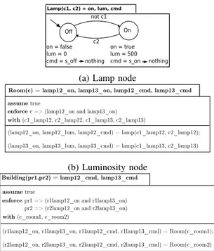
Figure 3a presents an example of automaton modelling a lamp. This automaton is contained in a node that has two input flows (c1, c2) and three output flows (on, lum, cmd). The automaton has two states (Off, On) and two transitions. Each state is associated to three equations that give values to the output flows. In the state Off, the output flows on and
lum are respectively equal to false and 0. This means that
the lamp is off and does not produce luminosity. The output flow cmd is equal to s_off (switch off) when the state Off is newly reached. Otherwise, it is equal to Nothing. The reason is twofold. First, the value of an output flow must be defined at each instant. Second, this prevents from continuously sending
cmd = s_off while the lamp is already switched off.
The initial state of the automaton is Off. When the input flow c1 is false, the automaton goes to the state On and the output flows takes the values given by the equations of this state. Otherwise (i.e., c1 is true), the automaton remains in the state Off. This means that there is an implicit transition associated to c1 that allows to remain in the state Off. Similarly, in the state On, when c2 is true, the automaton goes to Off. Otherwise, the automaton remains in this state.
Contract: A Heptagon/BZR contract has three parts: assume, enforce and with. The assume part defines the hypothesis on the system. The enforce part defines the properties (objectives) to enforce. The with part defines the controllable variables (i.e., the variables that will be used to enforce the objectives). From the contract, the DCS algorithm explores the model state space and computes the possible values of the controllable variables. The aim is to achieve the objectives whatever the values of the uncontrollable variables. For instance, the input flows c1 and c2 in the lamp automaton (Figure 3a) can be defined as controllable variables to enforce an objective related to the luminosity of a room. In this case, the DCS algorithm will compute their possible values.
After the controller synthesis, several solutions can be possible regarding the objective to achieve. For instance, the lamp can be Off or On to provide a luminosity greater or equal to 0 lux. However, one solution must be chosen. For this, the backend of the Heptagon/BZR compiler selects one of the solutions. It is possible to guide the selection with two options. Firstly, the compiler backend favours the value true to the value false for a boolean variable. For instance in the lamp automaton, to favour staying Off, the transition from Off to
On is associated to not c1. Here, the implicit transition that
remains in Off (associated to c1) is favoured by the compiler backend. The second option is that the compiler backend gives the value true to the variables following their declaration order. If this does not enforce the objectives, it changes the values of the variables, one by one, to false following the reverse of the declaration order. Hence, when declaring c1 before c2, if two transitions T1 and T2, respectively associated to not c1 and not c2 are possible, the compiler backend chooses T2.
Figure 3b presents an example of node with a contract to switch on the two lamps of a room when a presence is de-tected. This node has one input flow (c) and two output flows (lamp12_cmd, lamp13_cmd). This node defines two instances
On O not c1 c2 on = true lum = 500 cmd = s_on nothing on = false lum = 0 cmd = s_o nothing
Lamp(c1, c2) = on, lum, cmd
(a) Lamp node
with (c1_lamp12, c2_lamp12, c1_lamp13, c2_lamp13)
Room(c) = lamp12_on, lamp13_on, lamp12_cmd, lamp13_cmd
enforce c => (lamp12_on and lamp13_on)
(lamp12_on, lamp12_lum, lamp12_cmd) = lamp(c1_lamp12, c2_lamp12); (lamp13_on, lamp13_lum, lamp13_cmd) = lamp(c1_lamp13, c2_lamp13)
assume true
(b) Luminosity node
with (c_room1, c_room2)
Building(pr1,pr2) = lamp12_cmd, lamp13_cmd
enforce pr1 => (r1lamp12_on and r1lamp13_on)
pr2 => (r2lamp12_on and r2lamp13_on)
(r1lamp12_on, r1lamp13_on, r1lamp12_cmd, r1lamp13_cmd) = Room(c_room1); (r2lamp12_on, r2lamp13_on, r2lamp12_cmd, r2lamp13_cmd) = Room(c_room2)
assume true
(c) Modular node
Figure 3: Example of Heptagon/BZR program
of the lamp node (Figure 3a) and composes their automata using the parallel composition operator ;. The contract defines no hypothesis (assume true), one objective to enforce and four controllable variables. The objective means that when c is true (presence detected), both lamp12 and lamp13 must be on. The controllable variables are the input flows of the two lamp nodes and are used to enforce the target objective.
For a large system, using one node with a contract to enforce all the objectives is limiting. This generates one single controller for the whole system. In addition, the controller synthesis may take a lot of time or not succeed due to computing resources limitations. Indeed, exploring all the state space of a large system is time consuming and requires a lot of CPU and memory. To overcome this limitation, one can design a Heptagon/BZR program with Modular DCS.
b) Design of a Heptagon/BZR program with modular
DCS: This consists in dividing the system into several
subsys-tems, that handle different objectives. Then, defining for each subsystem, a node with a contract to enforce the subsystem objectives. This node instantiates and composes relevant au-tomata or other nodes. In this case, DCS is performed on each subsystem instead of on the whole system. This decreases the DCS execution time and its resources consumption.
Figure 3c shows an example of use of modular DCS in Heptagon/BZR. The Room node is instantiated twice, to model a small building of two rooms. This Building node takes as input two flows pr1 and pr2, modelling the value of a presence sensor in each room. Then, we add a global contract, in this node, ensuring that for each room, both lamps are switched on when a presence is detected by the associated
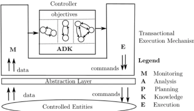
Abstraction Layer Controlled Entities M E Legend M Monitoring A Analysis P Planning K Knowledge E Execution data commands Transactional Execution Mechanism data commands Controller ADK objectives
Figure 4: LINC combined with Heptagon/BZR Control Loop
presence sensor. These objectives are enforced by means of two controllable variables: c_room1 and c_room2.
c) Execution of a Heptagon/BZR program: The
compi-lation of a Heptagon/BZR program generates a C code that includes a function called step. In case of modular DCS, several step are generated (one for each node with a contract) but one of them is the main step. The step (or the main step in case of modular DCS) takes as parameter the current values of the inputs, computes the outputs and updates the state of the automaton modelling the system, in a reaction loop.
One execution of the step function corresponds to one reaction of the system. Hence, the step must be executed each time a reaction is required. Executing the step requires to ensure the consistency between the state of the automaton (that models the system) and the state of the actual system. This is done by combining LINC and Heptagon/BZR.
2) Combination of LINC and Heptagon/BZR: It allows
to design and implement a control loop with a behavioural reliability and a transactional reliability. The behavioural re-liability is the absence of conflicts and objectives violations. The transactional reliability is the absence of inconsistencies resulting from communication errors or hardware failures.
Figure 4 presents a control loop designed through the combination of LINC and Heptagon/BZR. The controller of this loop is a step function. The step computes correct and coherent commands based on knowledge about the environ-ment (composition of automata). The step is executed by a LINC rule that collects the sensor data and executes the computed commands. This rule is triggered each time an event occurs (a new sensor value is produced). When triggered, the rule invokes the step with the collected data to compute the commands to send. Then the rule, in a transaction, sends the commands and executes the step to update the state of the automaton. If a command cannot be sent, the step is not executed and the state of the automaton remains consistent with the state of the actual system. More details about the combination of LINC and Heptagon/BZR can be found in [22]. D. Paper Contribution
We know how to build a single control loop, with two kinds of reliability, for smart environments. This paper addresses the composition of multiple control loops and their adaptation.
III. CONTROLLOOPSCOMPOSITION
This section presents patterns for control loops composition. A. Parallel control loops
Achieving a smart environment objectives (e.g., comfort, security) requires to design and implement multiple control loops. The control loops are in parallel and can have different types of controllers (e.g., set of rules, step). Each control loop consists of a set of objects and one or more LINC rules. For each controller one or more objects execute the rules. The objects and the rules of the control loops are independent.
1) Example of parallel control loops: Let us consider a
room equipped with a mechanical ventilation, a door and
three sensors (indoor presence, indoor CO2 and outdoor
presence). The devices of this room must be managed to achieve two objectives. The first objective is to maintain the
CO2 concentration under 800 PPM. The second objective is
to open the door when an outdoor presence is detected and close it otherwise. The first objective requires a physical model
of the room and the CO2 variation. Hence, this objective is
achieved by a control loop with a MPC based controller. The second objective is in the format of if then else and hence, it is achieved by a control loop with a hand written controller.
2) Problems of parallel control loops: Controllers of
Par-allel loops can be conflicting. This happens in two cases. First, when the effect of a controller violates an objective of one or more other controllers. For instance, let us consider a controller that opens the window of a room for natural ventilation. This violates the objective of another controller that uses the HVAC to heat the room. To minimise the energy consumption of the HVAC, this conflict must be avoided.
The second case in which controllers are conflicting is when they have, at the same instant, contradictory actions on the
same actuator. For instance, let us consider two controllers C1
and C2. C1opens the window to cool the room when specific
conditions are true (i.e., presence detected, indoor temperature
high and outdoor temperature low). C2 closes the window
when a presence is detected and the outdoor noise is high.
C1 and C2 conflict on the window when the room must be
cooled (i.e., presence detected and indoor temperature high), the outdoor temperature is low and the outdoor noise is high. Conflicts are avoided by coordinating the control loops. B. Coordinated parallel control loops
This is done as illustrated in Figure 5. A coordinator is in charge of controlling specific controllers of the loops based on data collected from the environment. A controller is con-trollable if it can be inhibited (its objective is not mandatory) and/or prevented from performing a specific action. Such a controller has a set of input parameters, called coordination variables, that allow to control it. For instance, let us consider
the controller example C1that cools the room by opening the
window. This controller has a coordination variable named window_access. The value of window_access (Usable or
NotUsable) specifies to C1 if it can use the window or not.
The coordination consists in giving appropriate values to controllers coordination variables. This is done manually in LINC when the number of control loops is not high. Other-wise, this is done automatically in Heptagon/BZR.
1) Coordination in LINC: This is done by writing
coordina-tion rules. A coordinacoordina-tion rule verifies specific condicoordina-tions and gives appropriate values to specific controllers coordination
variables. For instance, let us consider the controllers C1and
C2. A coordination rule is written to avoid the conflict on the
window. This rule first verifies if the last command computed
by C2, stored in a specific bag, is close. If so, the rule gives
the value NotUsable to the variable window_access of C1.
When the number of control loops is high, manually writing rules is tedious and can be error prone. In this case, the coor-dination is done using Heptagon/BZR. This ensures, through behavioural model and DCS, that all conflicts are avoided.
2) Coordination in Heptagon/BZR: The coordinator is a
step function that is executed by a LINC rule. The step
takes as parameter the collected data and computes a set of outputs. The computed outputs correspond to the values of specific controllers coordination variables. These variables are stored by the rule that executes the step in dedicated bags and are read by the rules of the controllable controllers.
The step is obtained through the design and the compila-tion of a Heptagon/BZR program. This program consists of a set of automata that model the actions of the controllers and a node with contract. The contract defines a set of properties that must be enforced for the coordination of the control loops. Once generated, the step function is executed by one LINC rule, following the execution scheme presented in [22].
a) Controller actions modelling: The actions a controller
can perform on a shared actuator are modelled as an au-tomaton. This automaton has states that correspond to the actions of the controller and an Idle state. In the Idle state, the controller does not perform an action. Each transition of the automaton is associated to the conditions that trigger the action corresponding to its target state. For a controller that is controllable, the states of the automaton are associated to equations that give values to the coordination variables of the controller. The automaton transitions can be associated to controllable variables that are used to enforce the properties.
For instance, Figure 6 shows the automaton that models
the actions of the controller example C1 on the window. This
automaton is contained in a node that has four input flows and two output flows. The input flows correspond to the inputs of
C1 (presence, indoor and outdoor temperature) and a variable
c(controllable variable). The output flow window_access is
the coordination variable of C1. The output flow open_window
specifies if the window is opened or not by C1. The automaton
has an Idle state and two other states that correspond to the
actions of C1 on the window (use, not use). Each state is
associated to two equations that give values to the output flows. Initially, the automaton is Idle. At this state window_access is equal to Usable and open_window is false. This means that C1 is allowed to use the window but does not need to open it. When, the room must be cooled, depending on the value
of c the automaton goes to State1 or State2. For instance, when the room must be cooled and c is false, the automaton goes to State2 and window_access is equal to NotUsable. Figure 7 shows the automaton that models the actions of the
controller example C2on the window. Initially, the automaton
is Idle. When a presence is detected and the outdoor noise is high, the automaton goes to State1. At this state, the output
flow close_window is true. This means that C2 closed the
window. This automaton does not have controllable variables
because C2cannot be prevented from performing an action on
the window. The automaton is used to observe the action.
To coordinate C1 and C2 in order to avoid the conflict on
the window, a Heptagon/BZR node with a contract is defined. This node is shown in Figure 8. It instantiates and composes, in
parallel, the automata modelling the actions of C1and C2. This
node defines a contract that prevents from opening and closing the window at the same instant. This node takes as input specific sensor data and returns the value of window_access.
b) Need for distributed coordination: Using one
coordi-nator for all the parallel loops can lead to expensive discrete controller synthesis. Indeed, the coordinator is designed using a global automaton that is the parallel composition of several automata (at least one for each loop). This automaton can have a large state space when the number of control loops is high. This can also lead to performances degradation at runtime. Indeed, the rule that executes the step reads all the collected data in its precondition part. This can make the object that executes the rule build an inference tree with a large size.
c) Distributed coordination: Several coordinators are
designed instead of one. In this case, the control loops are grouped into several subsets depending on the potential con-flicts. Each subset of control loops is then coordinated by a
stepfunction that is executed by a LINC rule. Each rule reads
relevant data instead of all. These LINC rules are executed by different objects. Each object builds a limited size of inference tree and the objects are distributed to increase the performance. However, using one coordinator for each subset of control loops can still be costly and lead to performance degradation. When the number of control loops in a subset is high, the rule of the coordinator reads several data in its precondition. Hence, it may be required to design several coordinators for each control loops subset. Instead of designing a large number of coordinators, the control loops are composed hierarchically. C. Hierarchic control loops
Control loops are designed with one or more hierarchy lev-els, as illustrated in Figure 9. This is motivated by hierarchical structuring in the target environment. For instance, a building consists of a set of floors and each floor is composed of rooms and corridors. Designing hierarchic control loops allows to consider large environments. This also allows for reusability. The controller of a loop can be reused, without modification to build another controller with an upper level of hierarchy.
1) Hierarchy in LINC: This is manually done by creating
objects and writing a set of rules for each control loop. Each rule of a control loop first reads data that can be produced
Legend M Monitoring A Analysis D Decision K Knowledge E Execution Coordinator data data Abstraction Layer data command Controlled Entities ADK M E data command data ADK Abstraction Layer data command Controlled Entities ADK M E data command Abstraction Layer data command Controlled Entities ADK M E data command
Figure 5: Coordinated parallel control loops
Idle
C1_actions (pres, itemp, otemp, c) = window_access, open_window window_acess = Usable open_window = false pres and itemp=High
and otemp=Low and c window_acess = Usable open_window = true window_acess = NotUsable open_window = false State1 State2
pres and itemp =High and not c not pres or item p<> Hig h
pres and itemp= High and not c pres and itemp= High and c
no t p res or item p <> H igh
Figure 6: C1 actions on the window
State1 Idle
pres and onoise = High
not pres or onoise <> High close_window = false
C2_actions (pres, onoise) = close_window
close_window = true
Figure 7: C2 actions on the window
by sensors or other rules (e.g., with an upper hierarchy level). Then, it makes decisions that can be commands to send to specific actuators or data to store in bags for other rules.
When the environment is large, to prevent from conflicting rules, Heptagon/BZR is used to perform the hierarchy.
2) Hierarchy with Heptagon/BZR and modular DCS: With
Heptagon/BZR and modular DCS, the hierarchy is straight-forward and is obtained as follows. The controllers, of the control loops, that have the lowest level of hierarchy are first designed. Each one of these controllers is obtained by defining a Heptagon/BZR node with a contract to enforce specific objectives. Then, these Heptagon/BZR nodes can be composed, hierarchically, to obtain controllers with a higher level of hierarchy. A multi-level hierarchy is obtained by, hierarchically, composing the Heptagon/BZR nodes of the
enforce not (open_window and close_window) with (c)
Coordinator(pres, itemp, otemp, onoise) = window_access (window_access, open_window) = C1_actions(pres, itemp, otemp, c);
close_window = C2_actions(pres, onoise)
Figure 8: Coordination of C1 and C2
controllers (that do not have the same level of hierarchy). For instance, let us consider the hierarchical control loops presented in Figure 9. The controllers ctrl1, ctrl2 and
ctrl3 are first designed, as shown in Figure 10a for ctrl1.
Then, ctrl4 is designed by composing ctrl1 and ctrl2 as shown in Figure 10b before being reused to obtain ctrl5.
3) Runtime structure of a hierarchic control loop: Let us
consider, in Figure 9, the hierarchic control loop composed of the controllers ctrl1, ctrl2 and ctrl4. The runtime structure of this control loop is not the same depending on whether it is built using LINC or using Heptagon/BZR.
a) The control loop is built using LINC: In this case,
the controllers (ctrl4, ctrl1, ctrl2) consist of three sets of LINC rules. These sets of LINC rules are separated and the control loop has the structure that is presented in Figure 9.
b) The control loop is built using Heptagon/BZR: In
this case, each controller is a step function. The step of
ctrl4(step_ctrl4) is the main step function. It performs a
global (synchronous) reaction by invoking at the same instant the step of ctlr1 and the step of ctrl2. To enable the execution of the controllers, step_ctrl4 is executed by a LINC rule following the execution scheme presented in [22]. Figure 11 presents the runtime structure of the control loop. When a relevant event occurs, the rule is triggered to invoke
step_ctrl4 which executes the two other step functions at
the same instant. This runtime structure is limited by the fact that one LINC rule is used to execute three controllers.
This can be improved using the following solution. First, each step (step_crl1, step_ctrl2, step_crtl4) is ex-ecuted by a LINC rule following the execution scheme pre-sented in [22]. Then, the execution of the three rules is handled appropriately, i.e., taking into account two facts. The first fact is that one reaction of step_ctrl4 is synchronous and involves the execution of both step_ctrl1 and step_ctrl2. The second fact is the relation between the inputs and the outputs of step_ctrl1 and step_ctrl2. One of these step functions can have an output which is an input of the other.
For instance, let us assume that step_ctrl2 has an output which is an input of step_ctrl1. In this case, the execution of the three LINC rules is handled as follows. When a relevant event occurs, the rule that executes step_ctrl4 is first executed, to produce the inputs that step_ctrl4 gives to step_ctrl1 and to step_ctrl2. Then, the rule that executes step_ctrl2 is executed before the rule that executes step_ctrl1, to produce the output of step_ctrl2 which is
ADK ADK Ctrl4 Ctrl5 Legend M Monitoring A Analysis D Decision K Knowledge E Execution Abstraction Layer data command Controlled Entities ADK M E data command Abstraction Layer data command Controlled Entities ADK M E data command Abstraction Layer data command Controlled Entities ADK M E data command
Hierarchic Control Loop L1
Hierarchic Control Loop L2
Figure 9: Hierarchic control loops
ctrl1 (...) = ... assume enforce ctrl1 objectives with (...) # automata for ctrl1 (a) ctrl1 Design ctrl4 (...) = ... assume enforce ctrl4 objectives with (...) ctrl1 (...) = ... assume enforce ctrl1 objectives with (...) # automata for ctrl1 ctrl2 (...) = ... assume enforce ctrl2 objectives with (...) # automata for ctrl2 (b) ctrl4 Design Figure 10: ctrl1 and ctrl4 Design
Legend M Monitoring A Analysis D Decision K Knowledge E Execution Abstraction Layer data command Controlled Entities ADK M E Abstraction Layer data command Controlled Entities ADK M E
data command data
command
ADK
Ctrl1 Ctrl2 Ctrl4
LINC Rule
Figure 11: Hierarchy in Heptagon/BZR
an input of step_ctrl1. The three LINC rules are executed in one logical instant (i.e., with the same inputs values). This is done because the reaction of step_ctrl4 is synchronous. In summary, this solution consists in enabling the distributed execution of a synchronous program. When the number of
step functions is high, a solution with formal verification, as
the one proposed in [9], can be used for behavioural reliability.
IV. CONTROLLOOPSADAPTATION
A control loop for smart environment must adapt to the changing objectives. The reason is that a realistic smart envi-ronment has several configurations with different objectives. For instance, the objectives to achieve in an office during working time are different from those to achieve during
Transactional Execution Mechanism Controllers Abstraction Layer Controlled Entities data commands ADK M E Legend M Monitoring A Analysis P Planning E Execution K Knowledge data commands ctrl_A ctrl_B ctrl_C ctrl_D ADK
Figure 12: Control loop adaptation
holidays. The adaptation of a control loop is done through the reconfiguration of its controller. This is enabled by the design of several controllers, instead of one, for a control loop. First, a controller is designed for each configuration of the environment. Then, the reconfiguration is done, as illustrated in Figure 12, by deactivating the current controller and activating another one when specific conditions are true.
When the controller to activate is a step function, the reconfiguration is not straightforward. It is possible only if the current state of the environment is an acceptable state of the controller. Otherwise the reconfiguration is not possible.
Let us consider a system and a controller designed in Heptagon/BZR (step function). To achieve its objectives, the controller accepts specific states of the system and rejects the other states (i.e., those that can violate its objectives). A state rejected by a controller is not allowed to be reached when the controller is activated. Hence, activating a controller that is a
steprequires to verify if the current state of the environment
is accepted by the controller. This not an easy task in general. The reason is that a state is accepted by a controller if it:
• belongs to the controller state space (set of known states);
• does not violate an objective of the controller;
• does not lead, through one or several uncontrollable
However, in a smart environment, the activation of a con-troller that is a step can be done using particular assumptions. For instance, the controller can be designed in such a way that its initial state is equal to a specific state of the environment. This allows to activate the controller when this state is reached. For instance, an office can have a night state where it is not occupied, completely closed, not heated and not ventilated. This state can be used as the initial state of the office controller that is a step. This enables its activation, at night.
1) Controller reconfiguration: Let us consider an office
that has two configurations: working time and holidays. Each configuration is associated to a controller (step function) that achieves specific objectives. These controllers have the same initial state which is the office night state. Each controller is executed by a LINC rule following the execution scheme presented in [22]. These LINC rules, called execution rules, are designed in such a way that they can be automati-cally activated or deactivated. For this, a LINC bag called
CurConfiguration is first created. This bag contains one
tuple indicating the office current configuration (e.g., working time). Then, the execution rules are designed, as shown in Listing 2 for the execution rule of the working time controller.
1 [ " O f f i c e " , " C u r C o n f i g u r a t i o n " ] . r d ( " workingTime" ) & # p r e c o n d i t i o n o p e r a t i o n s 3 : : { [ " O f f i c e " , " C u r C o n f i g u r a t i o n " ] . r d ( " workingTime" ) ; 5 # o p e r a t i o n s f o r commands s e n d i n g # o p e r a t i o n s f o r t h e w o r k i n g t i m e s t e p e x e c u t i o n } .
Listing 2: Working time execution rule
A rd on the configuration of the controller is performed in the beginning of the precondition and in the beginning of each transaction. This ensures that an execution rule is triggered only if the tuple corresponding to the configuration of its controller is present in the bag CurConfiguration. Hence, switching a controller for another one consists in removing the tuple of the bag CurConfiguration and adding the appropriate tuple. This is done by writing a LINC rule. For instance, Listing 3 presents the LINC rule written to switch the working time controller for the holidays one. This LINC rule is triggered when the event holidays_started occurs and the night state of the office is reached. The performance of this LINC rule consumes the event and the current configuration tuple (workingTime) and inserts the holidays tuple.
[ " O f f i c e " , " Event" ] . r d ( " h o l i d a y s _ s t a r t e d " ) & 2 [ " O f f i c e " , " S t a t e s " ] . r d ( " n i g h t " ) & [ " O f f i c e " , " C u r C o n f i g u r a t i o n " ] . r d ( workingTime" ) 4 : : { [ " O f f i c e " , " Event" ] . g e t ( " h o l i d a y s _ s t a r t e d " ) ; 6 [ " O f f i c e " , " C u r C o n f i g u r a t i o n " ] . g e t ( " workingTime" ) ; [ " O f f i c e " , " C u r C o n f i g u r a t i o n " ] . p u t ( " h o l i d a y s " ) ; } .
Listing 3: Switching rule example
When the controllers are numerous or the conditions of their activation/deactivation depend on past states and/or events, the reconfiguration is done, automatically, using Heptagon/BZR.
a) Reconfiguration through Heptagon/BZR: This is done
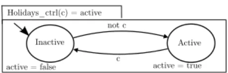
by designing a Heptagon/BZR program that consists of a set of automata (one for each controller) and a contract to
Inactive Active Holidays_ctrl(c) = active active = true active = false not c c
Figure 13: Holidays controller node
enforce with (c1,c2)
Recon g(holidays_started, workingTime_started, night) =
active_workingTime_ctrl = WorkingTime_ctrl(c1); active_holidays_ctrl = Holidays_ctrl(c2)
assume not (holidays_started and workingTime_started)
(holidays_started and night) active_holidays_ctrl (workingTime_started & night) active_workingTime_ctrl
active_holidays_ctrl, active_workingTime_ctrl
Figure 14: Controller reconfiguration
enforce a set of properties. Then, the Heptagon/BZR program is compiled to generate step function. This step takes as parameter a set of inputs and returns the controller to activate. This step is executed by a LINC rule which updates the bag
curConfigurationto activate the specified controller.
For instance, let us consider the office example. To enable the reconfiguration, each controller (holidays and working time) is modelled as an automaton, as shown in Figure 13 for the holidays controller. Initially, the automaton is inactive. When specific conditions occur, it becomes active.
Then, the Heptagon/BZR node presented in Figure 14 is defined. This node instantiates and composes the automata of the two controllers. The contract ensures that when the event holidays_started (resp. workingTime_started) occurs and the night state of the office is reached, the holidays (resp. working time) controller is active. This is done knowing that the two events (holidays_started, workingTime_started) do not occur at the same instant.
V. CASESTUDY
The aim of the case study is to control an office in order to achieve a set of target objectives. The case study is first described. Then, the objectives are achieved through parallel loops, coordinated parallel loops and hierarchical loops. A. Office description
The considered office consists of a room with: a window, a shutter, a door, a lamp, a Mechanical Ventilation (MV), a Reversible Air Conditioner (RAC) and a set of sensors (i.e.,
presence, luminosity, CO2, noise, temperature). Sensors are
installed outside the room to enquire outdoor conditions. The actuators and sensors of the room use different communication technologies (e.g., EnOcean, TelosB). Information about the meetings (day, time, features) in the office can be obtained through a specific agenda. The objectives to achieve are:
• For comfort, when a presence is detected, the luminosity
must be between 500 and 600 lux and the noise level must be lower than 80 dB;
• For comfort, when a presence is detected and the
tem-perature is lower than 17◦C (resp. greater than 27◦C), the
• For air quality, the room must be ventilated when a
presence is detected and the CO2 exceeds 800 ppm;
• For energy savings, natural lighting, ventilation, heating
and cooling are preferred to artificial lighting, ventilation, heating and cooling;
• For confidentiality, the office must be completely closed
during a confidential meeting;
• For air quality, the room must be quickly ventilated
between two meetings separated by less than 30 min;
• For air quality, the room must not be polluted by pollen
or outdoor CO2.
B. Objectives achievement through parallel loops
The objectives of the office are achieved by designing two control loops that do not communicate: Luminosity, TempAirNoiseConfid. The control loops are designed through the combination of LINC and Heptagon/BZR, to ben-efit from behavioural reliability and transactional reliability.
The controller of each loop achieves a set of objectives. For this, it takes as parameter a set of inputs and computes com-mands to send to specific actuators. For instance, the controller of Luminosity control loop maintains the luminosity between 500 and 600 lux when a presence is detected. It takes as input the values measured by two sensors (i.e., presence and outdoor luminosity) and computes commands to send to the lamp and the shutter. The controller of the TempAirNoiseConfid control loop achieves the objectives that are related to tem-perature, air quality, noise and confidentiality. This controller takes as input a set of values measured by specific sensors and information related to meetings. It computes commands for the window, the RAC, the MV, the door and the shutter.
Each controller is a step function generated through the compilation of a Heptagon/BZR program. This program con-sists of automata, that model the actuators targeted by the controller, and a contract to enforce the controller objectives.
1) Example of control loop design: Let us consider the
Luminosity control loop. The abstraction layer consists of
two PUTUTU objects (TelosB, EnOcean) that allow to com-municate with the loop target sensors and actuators. The con-troller is designed using two automata, that model a lamp and a shutter, and defining a Heptagon/BZR node with a contract. The lamp automaton is the one presented in Figure 3a.
Figure 15 presents the automaton that models the shutter. This automaton has two states (Closed and Opened). At each state, lum and air are associated to respectively specify the luminosity provided by the shutter and if it allows outdoor air to pass. For instance, when the shutter is closed, it provides a luminosity equal to 0 and does not allow outdoor air to pass. Initially, the automaton is at the state Closed. At this state, when the input flow c is false, the automaton goes to Opened and produces the command open. The transitions going from a given state to a different one are associated to not c. This allows to open or close the shutter only when necessary.
Figure 16 presents the node defined to enforce the objective of the Luminosity controller. This node has two input flows (presence and o_lum) and two output flows (shutterCmd
Shutter(c, o_lum) = cmd, lum,air
Closed Opened not c not c cmd = close nothing lum = 0 air = false cmd = open nothing lum = o_lum air = true
Figure 15: Shutter node
enforce presence lum in [500,600] with (c1_lamp, c2_lamp, c_shutter)
Lum(presence, o_lum) = shutterCmd, lampCmd
(on, lamp_lum, lampcmd) = Lamp(c1_lamp, c2_lamp); (shutter_cmd, shutter_lum, air) = Shutter(c_shutter, o_lum); lum = lamp_lum + shutter_lum
Figure 16: Room luminosity node
and lampCmd). The input flows respectively represent the values measured by the presence sensor and outdoor lumi-nosity sensor. The output flows respectively correspond to the commands to send to the shutter and to the lamp. This node defines a contract to enforce the target objective, through DCS, with the controllable variables c1_lamp, c2_lamp and c_shutter. These controllable variables are respectively related to the lamp and the shutter. The luminosity objective is expressed as follows: presence ⇒ lum in [500,600] where lum is equal to the sum of the luminosity provided by the shutter and the lamp. The fact that natural lighting is preferred to artificial lighting to save energy is expressed by declaring the controllable variables of the lamp before the one of the shutter. The compilation of the Heptagon/BZR program (i.e., nodes presented in Figures 3a, 15, and 16) generates a
step function. This function is executed by a LINC rule.
Figure 17 presents an execution trace of the Luminosity control loop. The variables time, presence and o_lum cor-respond to the time (in hour) and to the values measured by the presence sensor and the outdoor luminosity sensor. The variables shutter_opened and lamp_on correspond to the state of the shutter and the lamp. At 7 AM, a presence is not detected in the office and the outdoor luminosity is equal to 500 lux. In this case, the shutter is closed and the lamp is off. At 8 AM, a presence is detected (one office member arrives) and the outdoor luminosity is still equal to 500. In this case, the loop opens the shutter to maintain the luminosity between 500 and 600 lux while minimising the energy consumption. At 11 AM, the presence is still detected and the outdoor luminosity is equal to 700 lux. In this case, the loop switches on the lamp and closes the shutter, to achieve the objective. At 12, the presence is not detected, the loop switches off the lamp.
Each one of the control loops behaves correctly. However, during a confidential meeting, they conflict on the shutter. To avoid this conflict, the control loops must be coordinated. C. Objectives achievement through coordinated parallel loops
This is done by designing one coordinator in addition of the control loops Luminosity and TempAirNoiseConfid. This
Figure 17: Luminosity controller behaviour Lum(presence,o_lum,cconf1) = TempAirNoise(presence,i_temp,i_CO2,o_temp,o_CO2,o_noise, (shutterair,shutterCmd,lampCmd) (windowCmd,doorCmd, MVCmd,RACCmd) shutterair, o_pollen,co_noise,meeting,nextmeetingTime,cconf2) = presence lum in [500,600] enforce enforce enforce with with with (c_shutter, c1 lamp,c2_lamp) (...) = Shutter (c_shutter); (...) = Lamp(c1_lamp,c2_lamp) presence noise < 80 (presence and i_temp 17) heat (presence and i_temp 27 cool (presence and i_CO2 800) ventilation
between2meetings quickventilation not pollution
(c_window, c_door, c1_RAC, c2_RAC, c1_MV, c2_MV)
(...) = Window (c_window, i_CO2,i_temp,o_CO2, o_temp,o_noise,o_pollen,shtterair); # other automata
(presence and meeting and con d) ( shutter Closed and window Closed and door Closed) (cconf1, cconf2)
Office(presence,i_temp,i_CO2,o_temp,o_CO2,o_lum,o_noise,o_pollen,cor_noise,meeting,confid,nextmeetingTime) = (shutterCmd, lampCmd, windowCmd,doorCmd,MVCmd,RACCmd)
cconf1 shutter Closed
cconf2 (window Closed and door closed)
Figure 18: Modular DCS for the office
is done by first modelling for each control loop, the actions it can perform on the shutter, as an automaton. Then, defining a Heptagon/BZR contract with an enforce part specifying that the shutter must not be closed and opened at the same instant. The Heptagon/BZR program was compiled and the generated
step function was executed in a LINC rule. The composition
pattern coordinated parallel loops prevents from conflicts. However, it has a design cost that, with respect to the discrete controller synthesis time, is higher than the one of hierarchic and hence is less scalable. To give an illustration, the objectives of the office are first achieved through hierarchic loops. Then, a comparison between the design costs is done. D. Objectives achievement through hierarchic loops
This is done by designing two control loops: Lum and TempAirNoise. Each of them has a controller that is designed in Heptagon/BZR to achieve specific objectives. The Lum controller achieves the luminosity objective using the shutter and the lamp. The TempAirNoise controller achieves the objectives related to air quality and noise using the window, the RAC, the MV and the door. These controllers are not independent and must be managed. Indeed, heating, cooling as well as ventilating by opening the window requires the shutter be opened. Moreover, during a confidential meeting the shutter, the door and the window must be closed. The management is done hierarchically by a another controller called Office.
Figure 18 presents the node defined to design the Office controller. This node takes as input all sensors data and infor-mation related to meetings and returns the commands to send.
Table I: Comparison of coordinated parallel and hierarchic
Considered Environment Coordinated Parallel Loops Hierarchic Loops Office (7 automata) 3.9 s 1.2 s Open-space1 (10 automata) 6.6 s 2.08 s Open-space2 (13 automata) 12.6 s 4 s Open-space3 (16 automata) 22.3 s 7.7 s
It reuses the node of the controllers Lum and TempAirNoise and manages them. This is done by enforcing the confidential-ity objective and providing TempAirNoise with information about the shutter state (shutterair). The compilation of this node performs modular DCS and generates three step. E. Design cost comparison
Table I compares the execution time of DCS for parallel coordinated loops and hierarchic loops in four different envi-ronments. These environments consists of the office and three different open-spaces. The first open-space consists of two lamps, two shutters, two windows, one door, one RAC, one MV and one agenda. The second open-space has one more lamp, shutter and window than the first open-space and so on. The synthesis of the controllers was performed on a computer with a processor Intel i5 (2.4 GHz) and 4 GB of RAM.
The table shows that the pattern hierarchic control loops is less expensive, in terms of DCS execution time, than coordinated parallel loops. This is is enabled by modular DCS. F. Discussion about the case study
When designing the control loops Luminosity and the TempAirNoiseConfid, the proposed framework allowed for transparent communication with the office sensors and actua-tors. This was done by using specific objects that are defined in PUTUTU and did not require particular skills or knowledge. The framework also allowed for the automatic synthesis of the controllers through high level description of the actuators behaviours and the objectives. This prevented from manu-ally achieving the objectives of each control loop. Manumanu-ally achieving the objectives of a control loop would require to de-tect and avoid conflicts and make sure that they are all avoided. For instance, let us consider the TempAirNoiseConfid con-trol loop. An example of conflict is: open the window for cooling and close it, at the same instant, due to specific
conditions related to outdoor noise, outdoor CO2 or pollen.
Finally, the framework allowed for the control loops coor-dination and execution to achieve the objectives of the office.
VI. RELATEDWORK
In [1], [14], [13], [26], the authors propose solutions for adaptive systems. These solutions focus on the design of a single autonomic loop. This is limiting for large systems.
In [25], [5], [12], [24], the authors propose multiple au-tonomic loops for the management of large and/or complex adaptive systems. They identify one or more composition patterns (e.g., collaboration, hierarchy) and explain how they are coordinated to avoid conflicts. However, the coordination
is not based on a formal method to verify or ensure that all the conflicts are actually avoided, as we do in our approach.
In [15], [10], [2], [3], the authors propose solutions for reliable multiple autonomic loops. These solutions are based on a transition system to verify or ensure that the multiple au-tonomic loops are appropriately designed and/or coordinated. Our approach goes further by ensuring that the design, the coordination and the execution are appropriately done, we provide behavioural reliability and transactional reliability.
VII. CONCLUSION
This paper has proposed a design framework for reliable multiple autonomic loops. This paper targets the application domain of smart environments but the framework can be ap-plied to other domains (e.g., distributed systems deployment). The proposed framework allows for the reliable adaptation of realistic systems, where several objectives must be achieved, through the design and the coordination of multiple autonomic loops. Each autonomic loop is reliably designed by combining an automata based controller, a transactional execution mech-anism and an abstraction layer that hides the heterogeneity of the devices. The controller makes correct and coherent decisions (without conflicts) that are reliability executed by the transactional execution mechanism (without inconsistencies caused by communication errors or hardware failures). In the proposed framework, autonomic loops can be composed using the appropriate pattern (parallel, coordinated parallel, hierarchic), taking into account the impact on design and execution. Autonomic loops adaptation to deal with changing objectives in realistic smart environments is also proposed.
The propose framework was implemented using the transac-tional middleware LINC, the abstraction framework PUTUTU and the reactive language Heptagon/BZR. It was illustrated through a case study in the field of building automation.
An important perspective of this work is improve the runtime architecture of a hierarchic loop, the distribution of its controllers. Another perspective is to provide a domain specific language that allows developers to describe their target environments and objectives. Then, the aim will be to generate single or multiple autonomic loops that achieve the objectives.
ACKNOWLEDGEMENTS
This work is funded by H2020 TOPAs project (676760).
REFERENCES
[1] F. Alvares, E. Rutten, and L. Seinturier. Behavioural model-based control for autonomic software components. In Autonomic Computing (ICAC), 2015 IEEE International Conference on, pages 187–196. IEEE, 2015. [2] P. Arcaini, E. Riccobene, and P. Scandurra. Modeling and analyzing
mape-k feedback loops for self-adaptation. In Proceedings of the 10th International Symposium on Software Engineering for Adaptive and Self-Managing Systems, pages 13–23. IEEE Press, 2015.
[3] P. Arcaini, E. Riccobene, and P. Scandurra. Formal design and verification of self-adaptive systems with decentralized control. ACM Transactions on Autonomous and Adaptive Systems (TAAS), 11(4):25, 2017.
[4] P. A. Bernstein, V. Hadzilacos, and N. Goodman. Concurrency control and recovery in database systems, volume 370. Addison-wesley New York, 1987.
[5] J. Bourcier, A. Diaconescu, P. Lalanda, and J. A. McCann. Autohome: An autonomic management framework for pervasive home applications. ACM Transactions on Autonomous and Adaptive Systems (TAAS), 6(1):8, 2011.
[6] N. Carriero and D. Gelernter. Linda in context. Communications of the ACM, 32(4):444–458, 1989.
[7] T. Cooper. Rule-based programming under OPS5, volume 988. Morgan Kaufmann Publishers Inc., 1988.
[8] W. W. Dai, V. Vyatkin, V. Dubinin, and J. H. Christensen. Enhancing dis-tributed automation systems with efficiency and reliability by applying autonomic service management. In Emerging Technology and Factory Automation (ETFA), 2014 IEEE, pages 1–8. IEEE, 2014.
[9] G. Delaval, S. M.-K. Gueye, and É. Rutten. Distributed execution of modular discrete controllers for data center management. IFAC-PapersOnLine, 48(7):139–146, 2015.
[10] G. Delaval, S. M.-K. Gueye, E. Rutten, and N. De Palma. Modular coordination of multiple autonomic managers. In Proceedings of the 17th international ACM Sigsoft symposium on Component-based software engineering, pages 3–12. ACM, 2014.
[11] G. Delaval, É. Rutten, and H. Marchand. Integrating discrete controller synthesis into a reactive programming language compiler. Discrete Event Dynamic Systems, 23(4):385–418, 2013.
[12] S. Frey, A. Diaconescu, D. Menga, and I. Demeure. A generic holonic control architecture for heterogeneous multiscale and multiobjective smart microgrids. ACM Transactions on Autonomous and Adaptive Systems (TAAS), 10(2):9, 2015.
[13] D. Garlan, S.-W. Cheng, A.-C. Huang, B. Schmerl, and P. Steenkiste. Rainbow: Architecture-based self-adaptation with reusable infrastruc-ture. Computer, 37(10):46–54, 2004.
[14] E. Gjondrekaj, M. Loreti, R. Pugliese, and F. Tiezzi. Modeling adaptation with a tuple-based coordination language. In Proceedings of the 27th Annual ACM Symposium on Applied Computing, pages 1522– 1527. ACM, 2012.
[15] S. M. K. Gueye, N. De Palma, and É. Rutten. Component-based auto-nomic managers for coordination control. In International Conference on Coordination Languages and Models, pages 75–89. Springer, 2013. [16] J. O. Kephart and D. M. Chess. The vision of autonomic computing.
Computer, 36(1):41–50, 2003.
[17] M. Louvel and F. Pacull. Linc: A compact yet powerful coordination environment. In Coordination Models and Languages, pages 83–98. Springer, 2014.
[18] O. Mokrenko, S. Lesecq, Lombardi, et al. Dynamic power management in a wireless sensor network using predictive control. In Industrial Electronics Society, IECON 2014-40th Annual Conference of the IEEE, pages 4756–4761. IEEE, 2014.
[19] F. Pacull, L.-F. Ducreux, S. Thior, et al. Self-organisation for building automation systems: Middleware linc as an integration tool. In Industrial Electronics Society, IECON 2013-39th Annual Conference of the IEEE, pages 7726–7732. IEEE, 2013.
[20] M. A. Razzaque, M. Milojevic-Jevric, A. Palade, and S. Clarke. Middle-ware for internet of things: a survey. IEEE Internet of Things Journal, 3(1):70–95, 2016.
[21] A. N. Sylla, M. Louvel, and F. Pacull. Coordination rules generation from coloured petri net models. In PNSE@ Petri Nets, pages 325–326, 2015.
[22] A. N. Sylla, M. Louvel, and É. Rutten. Combining transactional and behavioural reliability in adaptive middleware. In Proceedings of the 15th International Workshop on Adaptive and Reflective Middleware, page 5. ACM, 2016.
[23] M. I. Vergara-Gallego, O. Mokrenko, M. Louvel, S. Lesecq, and F. Pac-ull. Implementation of an energy management control strategy for wsns using the linc middleware. In Proceedings of the 2016 International Conference on Embedded Wireless Systems and Networks, pages 53–58. Junction Publishing, 2016.
[24] P. Vromant, D. Weyns, S. Malek, and J. Andersson. On interacting control loops in self-adaptive systems. In Proceedings of the 6th International Symposium on Software Engineering for Adaptive and Self-Managing Systems, pages 202–207. ACM, 2011.
[25] D. Weyns, B. Schmerl, V. Grassi, S. Malek, et al. On patterns for decentralized control in self-adaptive systems. In Software Engineering for Self-Adaptive Systems II, pages 76–107. Springer, 2013.
[26] M. Zhao, G. Privat, E. Rutten, and H. Alla. Discrete control for the internet of things and smart environments. In Presented as part of the 8th International Workshop on Feedback Computing. USENIX.