HAL Id: cea-02506815
https://hal-cea.archives-ouvertes.fr/cea-02506815
Submitted on 12 Mar 2020
HAL is a multi-disciplinary open access
archive for the deposit and dissemination of
sci-entific research documents, whether they are
pub-lished or not. The documents may come from
teaching and research institutions in France or
abroad, or from public or private research centers.
L’archive ouverte pluridisciplinaire HAL, est
destinée au dépôt et à la diffusion de documents
scientifiques de niveau recherche, publiés ou non,
émanant des établissements d’enseignement et de
recherche français ou étrangers, des laboratoires
publics ou privés.
of fluorine in the French nuclear fuel cycle
J.-M. Borgard, F. Herbelet, B. Gwinner, J.-L. Fleche
To cite this version:
J.-M. Borgard, F. Herbelet, B. Gwinner, J.-L. Fleche. Thermodynamics analysis of the current
de-fluoration process of UF6 and its application for efficient recycling of fluorine in the French nuclear
fuel cycle. GLOBAL 2015 - International Conference on Advanced Nuclear Fuel Cycle and Related
Nuclear Systems, Sep 2015, Paris, France. �cea-02506815�
Thermodynamics analysis of the
current defluoration process of UF6
and its application for efficient
recycling of fluorine in the French
nuclear fuel cycle
Authors: J.M. Borgard1, F. Herbelet2, B. Gwinner3, J.L.
Fleche1
1 CEA, DEN, DPC, SCCME, LM2T, F-91191 Gif-sur-Yvette, France
2 CEA, DEN, DTEC, SGCS, L2ES, F-30200 Marcoule, France
3 CEA, DEN, DPC, SCCME, LECNA F-91191 Gif-sur-Yvette, France
Email: jean-marc.borgard@cea.fr
Abstract – In the nuclear fuel cycle, contrary to uranium,
fluorine is not recycled as it cannot be efficiently separated from the concomitant produced water. In this paper, modification of the current French deconversion industrial process to recycle hydrofluoric acid (HF) in an anhydrous form is examined. An alternative solution using a flash
drum to recycle overazeotropic mixture of HF/H2O into the
hydrolysis reactor is compared to previous propositions in terms of energetic cost and corrosion issue.
I. INTRODUCTION
Uranium and fluorine are intimately bound in the nuclear fuel cycle. Natural uranium has an insufficient isotopic 235 content to be used in the current light water nuclear reactors. Therefore, it has to be enriched in 235 isotope by separating it from the main 238 isotope in an efficient way. The only two processes, which have nowadays reached industrial large scale, namely gaseous diffusion and ultracentrifugation, require the use of uranium in gaseous state. Fluorine is the only chemical element that added to uranium, allows the generation of a stable gaseous molecule, the uranium hexafluoride (UF6) at moderate
temperature and benefits also from the advantage of a single stable isotope.
Depleted uranium can be deconverted in oxide form and can be used again, either to prepare MOx fuel combined with plutonium or stored for future use in fast breed reactors. On the other hand, fluorine is not currently recycled in the U cycle. To be efficiently recycled in the U cycle, it has to be preferably produced as anhydrous fluoride gas (AHF), as raw material for either uranium oxide fluorination into uranium tetrafluoride UF4 or
fluorine electrolysis [1] (fig. 1).
Fig.1. French nuclear fuel cycle and recommended pathway to recycle fluorine.
In the current industrial process, HF is produced in a hydrated form. The presence of an azeotrope around 38% weight HF (figure 2) makes this dehydration problematic and has not been yet implanted. Therefore, fluorine is either sold in aqueous form for external use or stored without deconversion in UF6 form. This storage presents
environmental, health, and safety risk because of the UF6
chemical instability: in contact with water or moisture chemical reactions producing hazardous material such as HF can occur.
Fig.2. HF-H2O mixture vapor-liquid equilibrium at atmospheric
pressure
The main alternatives to the current industrial deconversion process to produce anhydrous fluoride gas have been discussed by Morel [1]. Most of them use a third body extraction, which is problematic to conserve the uranium and fluorine compounds purity. Morel concluded that probably the best way was to use the chemical reactors of the current industrial process to remove the extra water. However, the different attempts [2],[3],[4] faced either corrosion and flow rate issues or too high energetic cost.
290 310 330 350 370 390 0 0,5 1 Tem p e ratu re (K ) HF concentration (weight) Bubble temperature Dew temperature
In this paper, the current industrial process is analyzed with thermodynamic and kinetic data. Modifications of this process producing AHF but with lower energy extra-cost, along with limited corrosion and safety issues will be discussed.
II. BASELINE OF THE CURENT INDUSTRIAL PROCESS
The current industrial process is split into two phases (figure 3): a hydrolysis of UF6 into UO2F2 and a pyrolysis
of UO2F2 into either U3O8 (for storage) or UO2 (for fuel
application). The hydrolysis of UF6 is done at medium
temperature (200-300°C) in gas phase and the pyrolysis is done at high temperature (650-800°C) with a mixture of hydrogen and water. The exhaust gas streams of pyrolysis are injected in the hydrolysis section and the exhaust gas of the hydrolysis reactor are condensed to remove the undesired extra hydrogen (if any) and inert gases in order to produce aqueous HF.
We can summarize the global reactions for the current deconversion process of UF6 as follow:
Hydrolysis : UF6(g) + 2 H2O(g) = UO2F2 + 4 HF(g) (1) Pyrolysis : UO2F2 + H2O(g) = 1/3 U3O8 + 1/6 O2(g) + 2 HF(g) ((2a) UO2F2 + 1/3 H2(g) +2/3 H2O(g) = 1/3 U3O8 +2 HF(g) (2b) UO2F2 + H2(g) = UO2 + 2 HF(g) (2c)
Fig. 3. Schematic of the current industrial process.
III. THE HYDROFLUORIC ACID CORROSION ISSUE IN THE DECONVERSION PROCESS
Hydrofluoric acid is known to be a very corrosive environment. The choices for engineering it are extremely limited.
In many aqueous applications, noble metals such as gold or platinum, and nickel alloys such as alloy 400 (MONEL) (65 wt.% nickel – 30 wt.% copper, iron and manganese additives) and alloy C-276 (55 wt. % nickel, 15 wt.% molybdenum, 15 wt.% chromium, iron and tungsten additives) are the only materials adequately resistant to attack for useful long-term service as stated by Schillmoller [5].
Nickel tends to react with HF to form a protective layer and nickel based alloys are highly resistant to pure HF. This resistance is however affected by three major factors: (i) the corrosion is greatly enhanced by the presence of oxygen O2 [6], (ii) it increases with temperature, and (iii) it
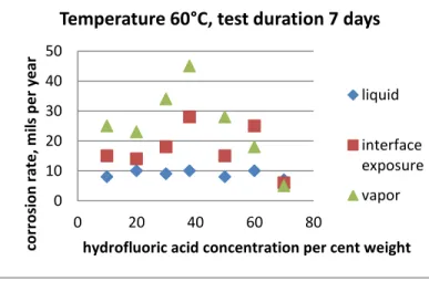
depends on the acid concentration. For the most promising materials, which are nickel based alloys, a sharp maximum corrosion rate is usually found close to the azeotropic point as shown by Braun [7] and later by Pray [8] for MONEL at 60°C (figure 4). Similar conclusion can be drawn from the corrosion tests for alloy C presented in table I [9].
Fig.4. Corrosion experiments measuring the effect of hydrofluoric acid concentration on corrosion of MONEL at 60°C
Table I
Laboratory tests of alloy C in aqueous solutions of HF solutions at boiling point under aerated atmosphere
HF % Temperature Duration
(days) Corrosion rate (mils/year)
5 Boiling 5 1 50 Boiling 4 180 65 Boiling 4 17 98 Boiling 3.6 1 0 10 20 30 40 50 0 20 40 60 80 co rr o si o n r ate , m ils p e r year
hydrofluoric acid concentration per cent weight
Temperature 60°C, test duration 7 days
liquid interface exposure vapor
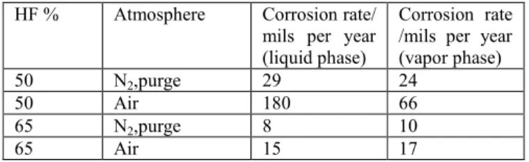
This is illustrated in table II [9] in which are compared the corrosion rates of alloy C measured under aerated and non-aerated in conditions close to the azeotropic point (50% weight) and for a more concentrated acid (65% weight).
Table II
Effect of oxygen and HF concentration on the corrosion of alloy C - 35 days tests at 60°C
HF % Atmosphere Corrosion rate/ mils per year (liquid phase)
Corrosion rate /mils per year (vapor phase)
50 N2,purge 29 24
50 Air 180 66
65 N2,purge 8 10
65 Air 15 17
As a consequence, it could be of critical importance to limit corrosion in the design of a deconversion process by avoiding the presence of oxygen and avoiding operation close to the azeotropic zone for HF/H2O mixtures,
especially when phase transitions are involved.
IV. THERMODYNAMIC ANALYSIS OF RECYLING OPTIONS :
Both hydrolysis and pyrolysis steps are in practice operated in the presence of an excess of water (see below) but also consume water (except the UO2 conversion variation) : 2
H2O for each U for pyrolysis according to equation (1) and
2/3 H2O for each U for pyrolysis according to equations
(2a and 2b). Both steps can in theory be used to remove the extra water from the hydrofluoric acid coproduced by the depletion process using a recycling loop as long as the recycled HF/H20 mixture does not perturb the chemical
reaction.
IV.A Hydrolysis of UF6
The hydrolysis of UF6 into UO2F2 is usually described by
equation (1) and can be done either in gas or liquid phase operation.
This reaction includes two major steps [10]:
UF6 + H2O = UOF4 + 2 HF(g) (3)
(G250°C ≈- 70kJ/mol U)
UOF4 + H2O = UO2F2 + 2 HF(g) (4)
(G250°C ≈ -95 kJ/mol U)
A minimum excess of water is essential for this reaction, to avoid that some UOF4 molecules remain trapped into the
UO2F2 product or that unreacted UF6 molecules flow
within the gaseous products.
Excess of incoming HF has little influence on the final product since both equations are straight forwards and kinetics is fast. Hence, the use of a recycling flow of H2O/HF will have no major impact on the final products of
the reaction. In fact, the inlet flowrate of the current process already includes some hydrofluoric acid generated by the pyrolysis reactor (see figure 3).
IV.B Pyrolysis of UO2F2:
Initial pyrolysis of uranyl difluoride UO2F2 is using
hydrogen free water hydrolysis (2a) but the current technology use equation (2b) for the coproduction of U3O8.
The advantage of hydrogen addition is to improve significantly the kinetics of pyrolysis as demonstrated by Knudsen [11] and also to limit strongly the presence of oxygen in the pyrolyser and in the exhaust gases. Therefore the corrosion inside the pyrolyser and in the downstream apparatus can significantly be reduced. However, a small amount of oxygen is present in the exhaust gases of the pyrolyser due to the fact that hydrogen is added in a slightly under stoichiometric ratio. Otherwise, extra addition of hydrogen over the stoichiometric ratio will produce unwanted UO2.
Equation (2c) is a variation of equation (2b) using over stoichiometric hydrogen to produce UO2 for fuel utilization
instead of U3O8. In practice it still uses extra water to avoid
the side-reaction of formation of UF4 through fluorination
reaction of UO2 with HF.
The pyrolysis section could in theory also be used to remove water using either (2a) or (2b) variations.
The reaction of equation (2a) can be split into three majors steps according to Lepeytre [12]:
UO2F2 + H2O = UO3 + 2 HF(g) (5)
UO3 = UO2,9+ 1/6 O2(g) (6)
UO2,9 = 1/3 U3O8 + 7/60 O2(g) (7)
The only one step affected by the HF concentration, equation (5) is equilibrated in the operational range of temperature with coproduction of HF (G720°C ≈ 0 kJ/mol).
According to Sabatier law, recycling of HF will then significantly lower the process kinetics.
Equation (2b) seems more attractive but can be split around 650°C [12] into three major steps, with the same first two steps of the previous process:
UO2F2 + H2O(g) = UO3 + 2 HF(g) (5)
UO3 = UO2,9+ 1/6 O2(g) (6)
UO2,9 + 7/30 H2(g) = 1/3 U3O8 + 7/30 H2O(g) (8)
The step involving HF generation is the same as the previous variation, hence the problem still remains. Kinetic tests done by Lepeytre [12] in various gaseous environments showed significant increase of the reaction time (figure 5) if extra HF is added to the incoming gas mixture in both cases.
Effective testing of this recycling strategy in a MONEL reactor by Hage [2] in addition to the hydrolysis recycling show incomplete conversion of UO2F2 samples even after
30 minutes at 650°C.
Corrosion is already a major issue in the pyrolyser due to the important resident time; as water potential removal is
only one third of the hydrolyser, it makes sense to limit the recycling loop to hydrolyser only.
Fig. 5. Comparison of pyrolysis reaction time at 650°C for various gas environments and water pressures [12]. Tests were done on 400 mg UO2F2 samples; results are based on gravimetric
measurements.
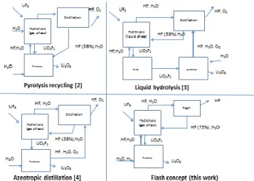
Two major options are still possible: operate the hydrolyser either in liquid or in gas phase. Both have been tried respectively by Hage [3] and Mestepey [4] (figure 6). They will be discussed below.
Fig. 6 : Schematic of the main alternative concepts based on the hydrolysis dewatering.
V. LIQUID PHASE HYDROLYSIS ENERGETIC ISSUE Liquid phase operation can be used to produce UO2F2 solid
product, because UO2F2 is highly soluble in water but
much less in the presence of concentrated hydrofluoric acid. The equilibrium diagram of UO3-HF-H2O mixture
was characterized by Ferris [13] and lately completed by Buslaev [14]. It suggests that, if operating the reaction at high HF content, it is possible to collect UO2F2 in solid
form and leaving high concentrated HF/H2O liquid phase
with very low uranium content. This liquid phase could be distillated to further produce anhydrous HF as proposed by Hage [3].
However, as stated by Buslaev [14], at high HF concentration the solid UO2F2 product is combined with a
lot of H2O and HF molecules. Drying the wet residue is
therefore energy intensive. Summary of the main results of Buslaev is presented in table III with our estimation of the associated energetic cost of drying for the UO2F2 using ©
Prosim software on the base of Vieweg estimation of HF-H2O enthalpy diagram [15].
TABLE III:
Estimation of the drying energetic cost per mol UO2F2.
Liquid phase HF% weight Wet residue HF % weight Wet residue UO3 % weight Drying energetic cost kJ/mol UO2F2 51.41 37.97 31.26 1397 64.69 49.16 22.6 2167 70.11 55.77 19.13 2562 78.64 61.31 20.1 3057 91.4 76.07 14.11 3145
Furthermore, solid-liquid separation is a slow process [3] and, on a safety standpoint, the critical mass of UO2F2 in
liquid phase is far lower than in gaseous phase operation, which strongly suggests preferring gas phase operation.
VI. GAS PHASE HYDROLYSIS ISSUE Mestepey et al. [4] proposed to combine the HF/H2O/O2
exhaust streams from the hydrolyser into a distillation column to generate anhydrous HF and azeotropic HF/H2O,
which could be recycled into the hydrolysis reactor (figure 6). The pilot plant was however stopped because of corrosion issues and difficulties to equilibrate the mass balance of the reactants.
An important source of fluctuation in the flowrate is the variable hydration of the uranyl fluoride molecule product. Values reported by Debacq [16] for an industrial reactor give an average value of one H2O per UO2F2 but the
hydration level of the UO2F2 molecule could locally vary
from zero to 2.
As a consequence the flow rate of HF/ H2O coming out
from the hydrolysis reactor is also variable; fine tuning of the distillation will be necessary if a pure HF gas exhaust and an azeotropic HF/H2O exhaust are required. Also both
HF gas exhaust and H2O/HF azeotropic recycling loop
flow rates will change. This will generate new operating conditions for the hydrolyser reactor; therefore generating a new hydration level of the UO2F2 product and the loop
will start fluctuate.
VI IMPROVEMENT OF THE RECYCLING CONCEPT: THE OVERAZEOTROPIC FLASH
The concept of hydrolysis recycling as tested by Mestepey can however be improved to limit corrosion and increase the system stability.
0 500 1000 1500 2000 0 500 ti m e (s)
Water Pressure (mbar)
H2O/H2 H2O/H2/HF H2O H2O/HF
As stated above, three possibilities are offered to minimize corrosion: limit the temperature of the recycling loop, operate far away from the azeotropic point in the HF/H2O
mixture, and limit the oxygen in the system.
The first point is then, in a similar way to the current industrial system, to operate the pyrolysis reactor in the presence of hydrogen (equation 2b) instead of solely water (2a), which will limit the presence of oxygen to a very small amount in the recycling loop.
To insure the stability of the response to variable concentrations of HF/H2O mixtures, a simple practical
solution for HF generation control can be found by exploring the liquid-vapor equilibrium of HF/H2O mixture.
As shown in figure 2, the vapor of HF/H2O in equilibria
with HF/H2O liquid at atmospheric pressure will remain
almost anhydrous as long as the composition of the liquid is above 65% HF [17, 18]. This specificity of the HF/H2O
mixture is kept in a very large range of temperature and pressure [19].
Therefore, if we replace the distillation column by a single flash drum and maintain the liquid exhaust overazeotropic with HF liquid concentration above 65% molar, we will get an almost anhydrous HF in vapor phase. Significant variation of temperature, concentration and pressure will not affect the anhydrous character of the vapor exhaust from the flash drum, allowing a much easier control of the recirculating loop.
This overazeotropic recycling has a second advantage: it also strongly limits the corrosion issue, because the whole recycling loop will now be operated in the overazeotropic range (over 65% HF) of the HF/H2O mixture.
The backdraft of the flash drum against the distillation column is that there is a larger recycle flow going into the hydrolysis reactor. However, exergy losses are much lower in such separator than with a distillation column and we may then expect a better global efficiency. This will be discussed below.
VII. COMPARISON OF ENERGETIC COST OF
ADVANCED PROCESSES :
A simplified version of the recycling process is described in figure 7, excluding supplementary equipment for safe operation of the recirculating loop (storage tanks, inert gases separation and liquid purge).
UF6 is injected through flow 1 in the hydrolysis reactor
(operated at a temperature around 250°C and pressure around 1.5 bar) where it reacts with the recycled HF/H2O
mixture (flow 6) and the exhaust gas from the hydrolyser (flow 2) to form an hydrated UO2F2 powder (flow 4) as
well as an overazeotropic flow of HF/H2O mixture (flow
3).This flow is either:
- condensed in the current industrial process for external sell
- injected in a distillation column operated at 0.95 bar
- injected in the flash drum operated at 50°C, 0.95 bar
The exhaust gas 5 is then compressed at 4 bar, liquefied at 65°C and cooled down to room temperature for further use. The HF/H2O liquid exhaust (flow 6) is then evaporated and
compressed to 1.5 bars for injection into the hydrolyser.
Figure 7 : Schematic of the improved recycling process
Typical flow rate are presented in table IV, assuming a 2 to 1 H2O/UO2F2(H2O) ratio for the gases and solid exhausts
from the hydrolyser and an exhaust gas of 3 H2O, 2 HF per
mole uranium for the pyrolyser, injected back into the hydrolyser, with an extra entrance flow of 2 H2O mole per
mole of uranium for the classical version.
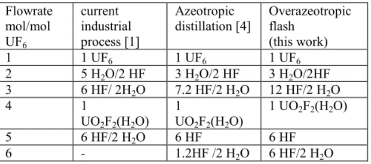
TABLE IV:
flow rate comparison between various concepts Flowrate mol/mol UF6 current industrial process [1] Azeotropic
distillation [4] Overazeotropic flash (this work)
1 1 UF6 1 UF6 1 UF6
2 5 H2O/2 HF 3 H2O/2 HF 3 H2O/2HF
3 6 HF/ 2H2O 7.2 HF/2 H2O 12 HF/2 H2O 4 1 UO2F2(H2O) 1 UO2F2(H2O) 1 UO2F2(H2O) 5 6 HF/2 H2O 6 HF 6 HF 6 - 1.2HF /2 H2O 6 HF/2 H2O
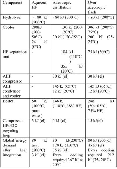
Table V presents the simulation of the different energy demands and release for the three different concepts based on simulations using Prosim software and Engels thermodynamic model based on Vieweg data [19].
The overazeotropic flash does not require any cold source in this simplified comparison but requires more heat because of the energy demand to boil and heat larger recycling flow. The amount (288 kJ/mol U) is however one order of magnitude lower than the drying of the UO2F2 wet
residue in the liquid phase concept.
Even more, as shown in figure 8, this amount of energy can be entirely provided by internal energy exchange by
recovering the heat release from the cooler, as long as intermediate boilers are used to match the temperature level of the heat released by the cooler. The extra energy demand can then be limited to the small amount of electricity (45 kJ/mol uranium) required for the compression of HF/H2O mixture and anhydrous HF.
TABLE V
Energy balance in kilojoules per mol of uranium converted
Component Aqueous
HF Azeotropic distillation Over azeotropic flash Hydrolyser - 80 kJ (200°C) - 80 kJ (200°C) - 80 kJ (200°C) Cooler 298kJ (200-50°C) 24 kJ (0°C) 130 kJ (200-120°C) 30 kJ (120-25°C) 306 kJ (200°C-75°C) 200 kJ (75-25°C) HF separation unit - 104 kJ (110°C ) 355 kJ (20°C) 75 kJ (50°C) AHF compressor - 30 kJ (el) 30 kJ (el) AHF condensor and cooler - 145 kJ (65°C) 12 kJ (20°C) 145 kJ (65°C) 12 kJ (20°C) Boiler 80 kJ (100°C, pure water) 146 kJ (110°C, 38% HF) 288 (50-105°C, kJ 75% HF) Compressor HF/H2O recycling loop
3 kJ (el) 5 kJ (el) 15 kJ(el)
Global energy demand after heat integration 80 kJ heat (200°C) 3 kJ (el) 80 kJ(200°C) 120 kJ (110°C) 35 kJ (el) Extra cooling required 367 kJ at 20°C 80 kJ (200°C) 45 kJ (el) Extra cooling required 212 kJ (75- 20°C)
Such strategy can be used for the heat demand for the azeotropic distillation column. However, a heat demand at 110°C of around 120 kJ/mol uranium will remain. Also the large heat release of the condenser (355kJ/mol) of the distillation column is operated around ambient temperature (20°C), requiring an additional important cold source to drive the distillation column.
Fig. 8 : Heat demand for evaporation of HF/H2O mixture (cold
stream) and heat release of cooling of HF/H2O mixture (hot
stream) according to simulations using Prosim © software for the overazeotropic flash.
VIII. CONCLUSIONS
Thermodynamics of the current industrial defluoration process was investigated to get anhydrous hydrofluoric acid.
The main opportunity in order to improve the system appears to use the chemical reaction of the hydrolysis reactor to eliminate the extra water.
A new flow-sheet is proposed, using a flash drum to recycle overazeotropic (over 65%) HF/H2O mixture into
this reactor. It allows the production of almost anhydrous HF for a very low extra energy demand, while strongly limiting corrosion issues.
REFERENCES
1. MOREL B., Duperret B., Uranium and fluorine in the nuclear industry, journal of fluorine chemistry 130 (2009), 7-10
2. HAGE, Improved process for recovering anhydrous hydrogen fluoride (AHF) from uranium hexafluoride (UF6), US patent 99/36352
3. HAGE, Process to produce commercial grade anhydrous fluoride gas (AHF) and uranium oxide from the defluorination of uranium hexafluoride, US Patent 6,352,677, mars 2002
4. MESTEPEY J., Recovery of anhydrous hydrogen fluoride from depleted gaseous uranium fluoride, US patent 5346684, September 1994
5. SCHILLMOLLER C.M., select the right Alloys for hydrofluoric acid service, chemical engineering progress, November 1998, p 49-54
6. R. D. KANE, S. M. Wilhelm, W. G. Ashbough, and R. G. Taraborelli,. “Simulate Chemical Process Corrosion in the Laboratory,” Chem. Eng. Prog. 89 (6),. 65–70 (1993)
40 90 140 190 0 100 200 Tem p e ratu re ( °C)
Heat duty (kJ/mol uranium)
Cold stream Temperature (°C) Hot stream Temperature (°C)
7. BRAUN W., Fink F.W.,Ericson, G.L., The corrosion of Monel and 70/30 Cupro-nickel in hydrofluoric acid”, atomic energy commission, Battelle Memorial Institute
Report n° 1237.
8. PRAY H. A., Fink F.W., Friedl B.E. and Braun, Corrosion resistant materials for hydrofluoric acid, atomic energy commission, Battelle Memorial institute report 268, June 15, 1953.
9. SCHILLMOLLER C.M. Corrosion resistance of nickel containing alloys in hydrofluorhydric acid, hydrogen fluoride and fluorine, publication n° 443, Nickel Development Institute Technical series, available at www.nickelinstitute.org
10. SHAO-WEN HU, Xiang-Yun Wang, Tai-Wei Chu, Xin-Qi Liu, Theoritical Mechanism Study of UF6
hydrolysis in the gas phase, J. Phys. Chem. A 2008, 112, 8877-8883
11. KNUDSEN I.E., Hootman H.E., Levitz N.M., A fluid-bed process for the direct conversion of uranium hexafluoride to uranium dioxide, chemical engineering division of Chicago, ANL 6066, February 1963- 34 pages 12. LEPEYTRE F.,, étude de la reduction de UO2F2.
Influence de la température, de la vapeur d’eau, du dihydrogène et du fluorure d’hydrogène, PhD thesis,
université Montpellier II, september 2002.
13. FERRIS L., Solubility of Uranyl Fluoride in Hydrofluoric Acid-Nitric Acid Solutions at 25°C, J. Am.
Chem. Soc., 1965, 87 (23), pp 5377–5379
14. BUSLAEV YU. A., Nikolaev N.S., Tananaev I.V., dokl. Akad. Nauk SSSR, 148, 882
15. VIEWEG R., Ein Enthalpie-Konzentration-Diagramm des systems Fluor-wasserstoff-Wasser, Chem. Techn. 15,
Jg., vol 1, januar 1963, pp12-14
16. DEBACQ M., Etudes et modélisation des fours tournants de difluorure d’uranyle, PhD thesis, université
Nancy-Lorraine, January 2001
17. MUNTER P.A., Aepli O.,Kossatz R., Partial pressure measurements of the system hydrogen fluoride-water,,
industrial and engineering chemistry, july 1949,
pp.1505-1508
18. MIKI N., Maeno M., Vapor-liquid equilibrium of the binary system HF-H2O extending toextremely anhydrous hydrogen fluoride, J. Electrochem. Soc., 137 (1990), p. 787-790
19. VIEWEG R., Betrachtungen zum system Fluor-Wasserstoff-Wasser, Chem. Techn. 15, Jg., Heft 12, dezember 1963, pp763-7403