Publisher’s version / Version de l'éditeur:
Proceedings of the American Society for Testing and Materials, 61, pp.
1250-1276, 1962-06-01
READ THESE TERMS AND CONDITIONS CAREFULLY BEFORE USING THIS WEBSITE. https://nrc-publications.canada.ca/eng/copyright
Vous avez des questions? Nous pouvons vous aider. Pour communiquer directement avec un auteur, consultez la première page de la revue dans laquelle son article a été publié afin de trouver ses coordonnées. Si vous n’arrivez pas à les repérer, communiquez avec nous à PublicationsArchive-ArchivesPublications@nrc-cnrc.gc.ca.
Questions? Contact the NRC Publications Archive team at
PublicationsArchive-ArchivesPublications@nrc-cnrc.gc.ca. If you wish to email the authors directly, please see the first page of the publication for their contact information.
NRC Publications Archive
Archives des publications du CNRC
This publication could be one of several versions: author’s original, accepted manuscript or the publisher’s version. / La version de cette publication peut être l’une des suivantes : la version prépublication de l’auteur, la version acceptée du manuscrit ou la version de l’éditeur.
Access and use of this website and the material on it are subject to the Terms and Conditions set forth at
The Influence of strain on shearing resistance of sensitive clay
Crawford, C. B.
https://publications-cnrc.canada.ca/fra/droits
L’accès à ce site Web et l’utilisation de son contenu sont assujettis aux conditions présentées dans le site LISEZ CES CONDITIONS ATTENTIVEMENT AVANT D’UTILISER CE SITE WEB.
NRC Publications Record / Notice d'Archives des publications de CNRC:
https://nrc-publications.canada.ca/eng/view/object/?id=bbcd939c-a460-48dd-8006-0be13c976b76 https://publications-cnrc.canada.ca/fra/voir/objet/?id=bbcd939c-a460-48dd-8006-0be13c976b76Ser TH1
N2lr 2 no.
156
c . 2
A N A L Y Z E D
NATIONAL
RESEARCH
COUNCIL
CANADA
DIVISION OF BUILDING RESEARCH
THE INFLUENCE OF STRAIN ON SHEARING RESISTANCE ,OF
SENSITIVE CLAY
BY
CARL B. CRAWFORD
R E P R I N T E D FROM
PROCEEDINGS O F T H E AMERICAN SOCIETY FOR TESTING AND MATERIALS VOL. 61, 1961, P. 1250
-
1276RESEARCH PAPER NO. 156
O F T H E
DIVISION OF BUILDING RESEARCH
B U I L D I N G RYSE4RCH PRICE 50 C E N T S
J U L 20
1952
OTTAWAYL
' I LULllgCIL JUNE 1962 NRC 6 6 6 2T h i s publication i s being d i s t r i b u t e d by t h e D i v i s i o n of Building R e s e a r c h of the National R e s e a r c h Council. I t should not be r e p r o d u c e d i n whole o r i n p a r t , without p e r m i s - s i o n of the o r i g i n a l p u b l i s h e r . T h e D i v i s i o n would be g l a d to be of a s s i s t a n c e in obtaining s u c h p e r m i s s i o n .
P u b l i c a t i o n s of t h e Division of Building R e s e a r c h m a y be obtained by m a i l i n g t h e a p p r o p r i a t e r e m i t t a n c e , ( a Bank,
E x p r e s s , o r P o s t Office Maney O r d e r o r a cheque m a d e pay- able a t p a r in Ottawa, t o the R e c e i v e r G e n e r a l of Canada, c r e d i t National R e s e a r c h Council) to t h e National R e s e a r c h Council, Ottawa. S t a m p s a r e not a c c e p t a b l e .
A coupon s y s t e m has been i n t r o d u c e d to m a k e pay- m e n t s f o r publications r e l a t i v e l y s i m p l e . Caupons a r e a v a i l - able i n denominations of 5, 2 5 and 50 c e n t s , and m a y b e ob- tained by m a k i n g a r e m i t t a n c e a s indicated above. T h e s e coupons m a y be u s e d f o r t h e p u r c h a s e of all National R e s e a r c h Council pablications including s p e c i f i c a t i o n s of the Canadian Government Specifications B o a r d .
Authorized Reprint from tlle Copyrighted Prorccdings of the
A~IERICAS SOCIETY FOR TESIISG A S D I\IATERIALS
Philadelphia, Pa.
Volume 61, 1061
A N A L Y Z E D
T H E I N F L U E N C E O F STRAIN ON SHEARING RESISTANCE O F SENSITIVE CLAY*
The effective stress shear strength parameters of a sensitive clay are subject to a wide degree of iilterpretation because the pore water pressure does not reach equilibrium a t maximum stress. A simple ~nethocl of obtaining shear strength in terms of fundamental parameters, believed to be equal to Hvor- slev's true parameters, is described. A revised interpretation of true cohesion for undrained tests is developed. Water content variation during the test is discussed, and the nlechanism of friction and cohesion is related to degree of deformation.
I n accordance with the fundamental principle of effective stress, the shearing resistance on any plane in a soil depends not on the total stress but on the effective stress on the plane
the
effective stress is the so-called grain-to-grain stress found by subtracting the pore water pressure from the total stress. I t is clear, therefore, that values for shear strength measured or applied without regard to pore water pressure may be subject to considerable error. Knowledge of this fact has created a great deal of interest in the measurement of shearing resistance in terms of effective stresses and the use of effective stresses in field application. Although the use of effective stress analyses is a great advance over the total stress method, i t is still an em-application of effective stresses has been on remolded or compacted soils in which stress history and sensitivity may have little influence. Because extrapolation of this experience into the realm of natural soils may not be justified, a special study of the shear strength properties of un- disturbed specimens of a sensitive clay is being carried out by the Kational Re- search Council of Canada, Division of Building Research. This paper describes a series of tests in which the effective stress shear strength parameters a r e subject to a wide range of interpretation, and an effort is made therefore to inter- pret the results in terms of fundamental parameters.
pirical approach dependent upon the
accuracy of arbitrary tests, usually on Thirty years ago Terzaghi (2) showed very small specimens, iiz representing that if two identical specimens of clay field conditions. Much of the study and are brought to the same water content-
one by simple compression, the other b y
* Presented a t the Sixty-fourth .4nnual Meet- additional followed by re-
ing of the Society, June 25-30, 1961.
I ~ ~Soil &Iechanics Section, ~~ d , i ~ i bound-the ~ i ~ ~former will be considerably
Building Research, National Iiesearcll Council, stronger t h a n the latter.
Ottawa, Canada.
2 The boldface numbers in parentheses refer This important discovery that the t o the list of references appeilded t o this paper. Stress history of a clay would have a
considerable influence on its strength was follolved by the classical work of Hvor- slev (3) who systeinatically traced the variation in the shearing resistance of remolded clay a s it was consolidated, rebounded, and recompressed. H e was able, b y relating shearing resistance to the "equivalent consolidation pressure" (that is, the pressure on the virgin consolidation curve corresponding to the void ratio a t failure), to obtain an espres- sion for shear strength in the form of two parameters which were unaffected b y stress history. These two parameters, called the "effective angle of internal friction" and the "effective cohesion," represent a frictional component of shearing resistance which depends only on the effective stress on the plane of failure, and a cohesive component which depends only on the void ratio in the plane of failure. Although Hvorslev still prefers the original terms (4), they have become widely known as the "true angle of internal friction" and the "true cohesion" to distinguish them from empirical parameters in terms of effective stresses (5-7).
T h e measurement of the Hvorslev parameters is usually such an involved procedure, requiring a good supply of uniform material, that i t has been carried out for only a very few natural soils. This is why engineers have continued t o rely on empirical parameters determined in terms of total applied stress or in terms of applied effective stress in which a relationship is established between shearing resistance and effective stress over a wide range of water contents. T h e values obtained in terms of total stress are applicable only if no drainage occurs in the test or in the field problem. T h e values in terms of effective stress can account for long-tern~ pore pressure changes, but if a substantial proportion of the shearing resistance of a soil actually consists of true cohesion the
direct application of empirical param- eters in terms of effective stresses may be of limited accuracy. I11other words, a s
the difference between the Hvorslev true angle of internal friction and the angle of shearing resistance in terms of effective stress increases, the departure from reality becomes of greater significance.
Sensitive clays present a special problem in the determination of effective stress parameters because t h e pore water pressure induced by shearing continues to increase after the maximum stress has been applied and the selection of the point of failure is controversial. This has led to a consideration of progressive shear strength parameter mobilization (8,9)
and of failure criteria other than a maximum deviator stress. I n a discussion submitted t o the recent ASCE Research Conference on Shear Strength of Co- hesive Soils (lo), the author presented test results showing that f o r a sensitive marine clay the computed angle of shearing resistance,
+',
increased with strain and was subject to variation of interpretation from 22 to 3 4 deg. Oster- man (11) reported similar test results on some Swedish clays in which "angles of u p to 41 deg were obtained for very soft clays, which cannot reasoilably be cor- rect." Although not a great deal of in- formation is available, t h e variety of soils in which pore pressures continue t o increase after the maximum deviator stress has been applied m a y be quite extensive. Parry (12) reports this phenom- enon for t h e insensitive London clay.The tests reported in this paper were made on samples of a late glacial marine clay called "Leda" clay. T h e properties of this clay, which occurs extensively in eastern Canada, have recently been sum- marized (13). The primary set of tests
were performed on specimens cut from undisturbed block samples obtained from a small tunnel a t a depth of 33 ft. T h e second set of tests are from a pre-
Series"
TABLE I.-PILOPERTIES OF T H E SOIL.
Specimens
Soil Properties
I
Depth, f t . . . . . . . .
Elevation, f t . .
Natural water content, per cent. . . . Liquid limit, per cent.
Plastic limit, per cent. . . Specific gravity. . .
Clay size, per c e n t . . . . .
. . . . Salt in pore water, gm per 1. Field vane strength, kg per sq
cm . . .
Sensitivity (appros).. . . Preconsolidation pressure, kg
. . . per sq c n ~ .
viously reported study of strain rate in- fluences (14) and are quoted in support of the conclusions drawn from the primary tests.
T o reduce the scatter in test results, special efforts were made to obtain samples of nearly uniform water content, although this is not a general feature of the clay. Further, the samples were ob- tained from a depth believed to be below surface weathering effects. The char- acteristics of the two sets of samples, which were located about three miles apart in the City of Ottawa, are sum- marized in Table I.
Specimen
Consolidated undrained triaxial tests were performed on specimens 10 sq cm in area and 8 cm high, wrapped in prepared
96-4
1
83-27Z C b
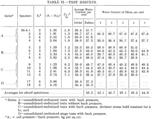
TABLE 11.-TEST RESULTS.
I -- 33 222 58 53 25 2 . 8 0 62 2 . 0 0 . 5 5 50 2 . 4 Average Water Content, per
1
cent 16 234 67 65 28 2 . 8 0 60 0 . 5 0 . 6 4 20 2 . 3 Initial Failure -- 5 9 . 4 5 1 . 7 6 0 . 7 47.1 5 9 . 0 4 1 . 8 5 9 . 0 3 7 . 3Water Content of Slices, per cent
Averages for sliced specimens . . .
1
4 3 . 3I
4 2 . 11
42.71
4 3 . 1/
43.5/
4 4 . 0a Series 1%-consolidated-undrained tests with back pressure,
R-consolidated-undrained tests without back pressure,
C-consolidated-undrained tests wit11 back pressure, deviator stress held constant for 5 hr, and
D-consolidated-undrained stage tests with back pressure.
"
Z, = cell pressure-back pressure, kg per sq cm.( E , - ~ 3 = ) deviator stress a t failure kg per sq cm ~
filter paper drains as described by Bishop and Henkel (15) and enclosed in a single thin rubber membrane (0.01 cm thick). I n series A, C, and D , cell pressure was then increased until small increments in cell pressure created equal increases in pore water pressure. This always oc- curred before the cell pressure reached 0.5 kg per sq cm. Cell pressure was then increased to 2.5 kg per sq cm while a back pressure of 0.5 kg per sq cm was maintained on the pore water, using equipment previously described (16). Drainage was allowed for one day. For tests a t higher cell pressures, daily increments of 1 kg per sq cm were ap- plied, allowing a t least two days for drainage under the last increment. I n series B, the specimens were consolidated without any back pressure, but just be- fore shearing, the cell pressure and pore water pressure were increased simul- taneously by 1 kg per sq cm. After consolidation was complete, the drainage was discontinued, and the specimens were strained by axial loading a t a rate of about 2 per cent per hr while pore water pressure was measured a t the bottom plate.
In series C, the deviator stress was held constant a t about one third of its maximum value for a period of 5 or 6 hr. During this period, the specimens continued to deform, and pore pressures increased slowly. Controlled axial strain was then continued by further axial loading.
The two specimens of series D were subjected to multiple-stage tests. This technique has been described recently by Kenney and Watson (17). I n these tests, a back pressure was applied to the pore water during consolidation and shear. Consolidation pressures of 2, 3, 4, and 6 kg per sq cm were used in succes- sive stages. After each consolidation stage, the dimensions of the specimen were computed, and an axial load was
applied by colltrolled straining without drainage until a maximum deviator stress was reached.
TEST RESULTS
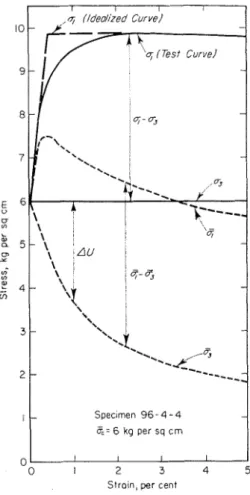
Test results are summarized in Table 11. The relationship between strain and deviator stress and pore water pressure
" 0 I 2 3 4 5
S t r a i n . per cent FIG. 1.-Typical Test Results.
for the four specimens of series A is shown in Fig. 1. Similar results were ob- tained for the other tests, but the pore pressure measurements for series B (consolidated without back pressure) appeared to be less reliable. For speci- men 96-4-7, in particular, the measured pore pressure was low and not consistent v i t h the other tests. In series C, about 0.2 per cent strain occurred during the period of constant deviator stress, and pore pressure increased in proportion to
strain as shown in Fig. 2. Specimen 96- and the average variation is shown in Fig. 4-10 was inadvertently stressed to 46 per 3. Slice 1 is the slice enclosing the fail- cent of failure and has therefore greater ure plane. T h e position of the other slices pore pressures than normal. is shown in the figure. T h e average water
ecirnen UC o;-ff3
9 6 - 4 - 9 2 0.43 6 m i n
96-4-10 3 0.86 14
96-4-11 4 0.89 9 37
96-4-12 6 1.32 1 7 , ' 35
Change i n Axiol Strain, per cent
FIG. 2.-Relation Between Pore Pressure and Strain a t Constant Stress.
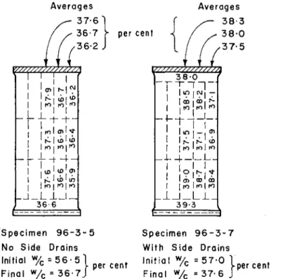
FIG. 3.-Average Water Content of 10 Speci- 111ens After Shearing.
T e n of the specimens were removed a s quickly as possible from the triasial chamber and divided into slices parallel to the failure plane in order to measure water content variation between slices. Specimens in which the failure plane was not clearly visible were compressed rapidly in unconfined compression t o establish the failure plane. T h e water content of each slice is given in Table 11,
content of the ten specimens a t failure is 43.3 per cent. The average water con- tent of t h e slice enclosing the fz'l i ure
plane is 42.1 per cent. T h e water con- tent of all of the specimens decreased consistently toward the failure plane, averaging 44 per cent a t t h e extremities to 42.1 per cent a t the failure plane.
Two specimens from an adjacent block sample were consolidated under one loading increment of 6 kg per sq cm and then removed from the cell quickly with- out shearing. End slices were removed, and the specimens were divided into upper, middle, and lower sections. Each section was trimmed concentrically into an outer, intermediate, a n d central portion. Water contents of each portion were determined. These tests revealed a pattern of water content t h a t suggests different degrees of consolidation throughout the specimen. T h e tests show the outer shell to have been about 1 p e r cent dryer than the central portion (Fig.
4). Most of slice 1, obtained from sheared specimens, came from the inner portion of the sample, while most of slice 4 or 5, for instance, came from the outer shell, and it is therefore reasoned that slice 1 was wetter than average before shearing. Since it was dryer than average after shearing, this suggests an even greater movement of water during shear than is
Averages
r ,
::,"
to be normally consolidated with c' = 0. At 1 per cent strain, when 90 per cent of the maximum deviator stress had been applied, the computed
+'
was 19 deg, a t 95 per cent it was 21 deg, and at 100 per cent it had risen to 26 deg, a t a strain of nearly 3 per cent. At approximately 10 per cent strain, the maximum principal effective stress ratio, ( T ~ / ( T ~,
occurred andAverages 3 8 . 3 S p e c i m e n 9 6 - 3 - 5 S p e c i m e n 9 6 - 3 - 7 No S i d e Drains W i t h S i d e D r a i n s Initial
W/c
= 5 6 . 5 I n i t i a l W/c = 5 7 . 0 F i n a l W/c = 3 6 . 7 F i n a l W/c = 3 7 . 6FIG. 4.-Water Content Variation After Triaxial Consolidation.
indicated by measurements on slices parallel to the failure plane.
DISCUSSION OF TEST RESULTS
The fact that the computed angle of shearing resistance,
+',
of a sensitive clay is subject to a wide interpretation is disturbing. Consider specimen 96-4-4, consolidated under a n all-round pressure of 6 kg per sq cm. Since this pressure is well above the natural preconsolidation pressure of the soil, it may be consideredthe computed
+'
was 34 deg. The ap- plication of the last 10 per cent of maxi- mum deviator stress has therefore in- creased the possible computed+'
by a s much as 15 deg, but only after con- siderable strain. This poses the important question of whether or not the triaxial test satisfactorily represents ill. sitzccoilditions of stress and strain for this sensitive, brittle soil.
I t is thought that after about 80 to 90 per cent of the maximum stress has been
applied, the soil begins to creep and build mum angle of obliquity" a t failure as u p pore pressures n~hich are not com- defined by Taylor (18). At half maximum patible with field phenomena. I n the deviator stress, the maximum angle of
3 0 2 5 + Stage 3 a t q = 4 0, w 0 S t a g e 4 a t
q =
6 Q i 3 2 0 15 0 2 0 4 0 6 0 8 0 100 P e r c e n t M a x D e v i a t o r S t r e s s FIG. 5.-Relation Between+'
and Deviator Stress.following analysis therefore the maxi- mum deviator stress is considered to represent failure, and an effort is made to interpret test results a t stresses well below failure. At half maximum deviator stress, for instance, the specimen has a factor of safety, F , of 2. Since c' = 0, the shearing resistance a t stresses less than failure may be represented by:
tan 4' S = a - -
I:
where
+',
the maximum angle of shearing resistance, is equivalent to the "maxi-obliquity, a ,
,
iss i r 1
r-)
. . Then :tan 4' = F tan a,,,
= 2 tan a,
For specimen 96-4-4, when F = 2, a,,, =
9 deg and
4'
= 17 deg.When
4'
was computed i n this way a t various degrees of maximum stress, it n7as found to be fairly constant u p to about half maximum deviator stress. Furtheri
S E R I E S A iI
9 6 - 4 - 5 2/
SERIES 'B1
0 ) n*
3 04
9 6 - 4 - 9 2 S E R I E S , C X 96-4-10 3 Stage 1 2 x Stage 2 3 0 S t a g e 4 6 0 0 . 5 1.0 1.5 S t r a i n , p e r c e n tS t r a i n , p e r c e n t
stressing caused a marked increase in computed 4'. I n Fig. 5 , values are plotted for specimens of series A and D. A simpler relationship was found between
4' and per cent strain. Additional test results plotted in this way are shown in Fig. 6. Curves were drawn through points up to maximum deviator stress, but since the curves were practically straight beyond 1 per cent strain the values are shown only to 1.5 per cent strain.
The significant feature of these rela- tionships is that the computed 4' a t low
other tests and can be carried out on only one specimen over a wide stress range. The series of previously published tests on Leda clay (14) have been analyzed in the same way and are shown in Fig. 7. These results, which were obtained from samples from another location and in which the rate of strain was varied from about 0.1 per cent to 10 per cent per hour, reveal a similar value for 4' of about 15 to 17 deg a t low strains which appears to be independent of rate of strain. Tests a t consolidation pressures
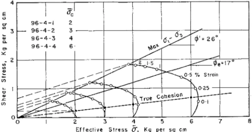
Specimen 9 6 - 4 - 4
zc = 6 kg per sq c m
Criflcal Slrsr. Palh
0 I 2 3 4 5 6 7
E f f e c t ~ v e Stress 5. kg per s q c m
RG. 8.-Efiective Stress Circles a t Various Degrees of Strain.
stresses is practically coilstant a t a n average of about 17 deg and is inde- pendent of consolidation pressure. Note that specimen 96-4-1 lies slightly above the average because the laboratory con- solidation pressure is slightly less than the silu preconsolidation pressure. Series B test results are scattered, probably because specimens were not consolidated under back pressure and the measured pore pressure is less reliable. Series C shoxs considerable scatter in the low strain range because 4' was computed just before and just after a period of several hours a t constant stress. The stage test of series D is especially significant because it agrees with the
less than 3 kg per sq c m give liigher values of 4' and appear to be affected b y
the natural overconsolidation.
From these test results, i t is thougl~t that the computed 4' of 17 deg is a fundamental parameter equivalent t o Hvorslev's true friction angle 4,
.
For discussion, reference is made to Fig. 8which shows Mohr stress circles for specimen 96-4-4 a t various degrees of strain up to 10 per cent. T h e maximum angles of oblicluity a t strains of 0.25 per cent and 0.5 per cent are 5 and 9 deg, respectively, and the computed values of 4' are 16.9 and 17.1 deg. I n this stress range, rather little change occurs in the effective stress on the plane of masiinu~n
obliquity. I t is reasonable to suppose that the true frictional resistance is not fully developed. At 2.5 per cent strain, the maximum deviator stress is reached. Since effective stress on the failure plane is reduced to about 60 per cent of its maximum, the frictional resistance is fully developed and the shearing re- sistance envelope is drawn at an angle of h = 17 deg intersecting the ordinate axis at a value of 0.65 kg per sq cm. This is regarded as the true cohesion, c,,
defined by Hvorslev and is thought to be
solidation pressure as postulated by Hvorslev for remolded specimens. I n the lower part of the figure, the relationship between true cohesion and consolidation pressures is illustrated. The Hvorslev "coefficient of effective cohesion" is 0.11. Although systematic observations have not been made, it has been casually observed that the shear planes at failure in this material are inclined at about 55 deg to the horizontal, giving further confirmation to the reported value of
4 e (1).
E f f e c t i v e S t r e s s
5,
K g per s q cm FIG. 9.-Effective Stresses on Most Critical Shear Planes.due to prestressing (19) on the failure plane. Other values at various strains are shown. At 0.5 per cent strain, it is thought that some true cohesion is developed due to prestressing even though friction is not fully developed. A solid curve is drawn through points of tangency to the Mohr circles to in- dicate the effective stress on the most critical shear plane which gradually steepens as friction is mobilized. This "critical stress path" is similar to but not quite the same as the "vector curve" employed by Casagrande and Wilson
(19). A set of "critical stress paths" ob-
tained in test series A is illustrated in Fig. 9. These indicate that the magnitude of true cohesion is dependent on the con-
DRAINED TESTS
Some consolidated drained tests have been made on this sensitive clay, but none is reported in the paper. I t has been found that when axial stress is increased with full drainage, the specimen deforms up to 30 per cent strain or more before maximum strength is reached, and it has been argued that such a test has no practical significance (10,14). If the speci- men is caused to fail by decreasing the lateral stress, the relationship between computed 4' and strain is similar to that measured by an undrained test, but considerable strain is again necessary for failure (10). The reasoning applied to consolidated undrained tests can not be extended to the drained tests because
there is no period of more or less con- stant effective stress on the failure plane.
For relatively insensitive remolded clay, Henkel (20) found strength in terms of effective stresses to be independent of type of test, drained or undrained, but he was unable "to relate shear strains measured in the various types of tests." H e drew attention to the necessity of relating shear stress and shear strain for practical problems and cautioned against extending his laboratory results to field problems.
For both undisturbed and compacted clays, Hirschfeld (21) found the relation- ship between strength and effective stress to be dependent on test method (drained or undrained). From a study of many test results, he concluded that time of loading and prestress are the most im- portant factors influencing the relation between shear strength and effective stress in a saturated clay.
Test results for a Drammen clay have been reported in sufficient detail by Bjerrum and Simons (9) to permit deter- mination of its "true angle of internal friction" by the described method. This clay, with a liquid limit of 37 per cent, plastic limit of 18 per cent, and natural water content of 34 per cent, is com- puted to have a true angle of about 18 deg
.
Tests described by Simons ((22), Fig. 1) on a highly plastic clay from Canada, for which sufficient information was avail- able, gave a computed true angle of internal friction of about 16 to 17 deg. Tests by the Division of Building Re- search on samples from the same area gave approximately the same value.
The results of several investigations on the stress variation in a specimen during
a triaxial test were summarized by Hvorslev (23). Shockley and Ahlvin (24)
reported significant stress variation and opposite volume change tendencies in various portions of sand specimens being sheared in a triaxial device and con- cluded that "interpretations of test data based on total volume changes may be completely a t variance with those determined on the basis of changes in the failure zone alone." The late D. W. Tay- lor reported that "non-uniform condi- tions of stress and strain occur in all types of tests, and failures are always, to a degree, progressive" (18). Taylor measured pore pressures within clay specimens, and after shear he measured the variation in water content. His re- sults, just recently published by Whit- man (25), show variations of 1; per cent. Similar results are quoted in this paper. I t is difficult, if not impossible, to make allowance for stress variation and water migration within a specimen during the triaxial test. I t is useful, however, to attempt to judge the significance of these complications in special tests on reason- ably uniform specimens. This is done with reference to Fig. 8. Initially, it is reasoned that as the shear stress ap- proaches its maximum value the struc- ture of the sensitive clay breaks down and transfers normal stresses to the pore water, causing water to flow from the most critical plane. As friction develops progressively, the critical plane steepens
4
to an angle of 45
+
to the horizontal.2
If the material remained homogeneous, the critical plane would maintain its position, but if consolidation occurs on the plane, it will tend to move up or do~vn or to steepen. If a progressively steepen- ing plane due to mobilization of friction is visualized, it is thought t h a t this trend will continue because a shift up or down in the specimen would require the critical plane to move into a region previously
affected by consolidation. If the critical plane steepens due to progressive drying, the failure envelope will intersect the Mohr circles which are computed from total stresses minus measured pore water pressure, and the "critical stress path" will trend toward that shown by a broken curve in Fig. 8. Casagrande and Wilson (19) used similar reasoning to explain variation in the shape of "vector curves" depending on type and rate of stressing.
There has not been satisfactory agree- ment on the true mechanism of friction and cohesion in clay soils. On the basis of experiments with remolded clays, Rowe
(26) suggested that true cohesion may be unstressed a t equilibrium and that creep
physicochemical concepts of soil water systems and emphasized the importance of considering a portion of the water in a soil as part of the soil particles. This concept led him to conclude that when the pressure between mineral grains is released they will continue to stick to- gether because of adhesional forces. This is thought to be a most important con- cept and is employed in the following explanation for the development of friction and cohesion in the Leda clay. I t is believed, based on test results re- ported in this paper, that all shearing resistance is of a frictional nature (that is, dependent on normal effective stress on the plane of shear) and that cohesion is caused by the inability of the inter- particle forces to decrease quickly (Rosenqvist's adhesion) when external would result if true cohesion were loads are released. I t follows that t h e mobilized. Lambe (27) saw no fundamen- frictional component
(9,
= 17 deg) is tal difference between the mechanism of independent of time or stress path. T h e friction and cohesion. He argued (28) cohesioil component, on t h e other hand, that cohesion was mobilized a t very small is dependent on stress release and may strains, and a t some further degree of be expected to begin to dissipate as soon strain it ceased to contribute to shearing as i t is mobilized. I t will probably not resistance. From a comprehensive set of decrease to zero. Soils which have been tests on a variety of soils, Schmertmann rebounded geologically might be es- and Osterberg (29) conclude that the pected to retain a minimum cohesion. "cohesion strength component generally This could account for the "threshold develops to its maximum value a t an effect" observed by Bjerrum and LVu axial compressive strain of less than 1 (7).per cent, while the friction angle requires Friction in clays will probably not be a much greater strain to reach its masi- as simple as friction between ordinary illurn value." For normally consolidated plane surfaces since i t is not thought to Lilla Edet clay, Bjerrum and TVu (7) involve direct mineral contact. Rather,
found true cohesion to be proportional to it will be increased by decreasing distance the coilsolidatioil pressure. Specimens between particles and by enlarged over- reconsolidated in the laboratory to lapping of water films. I t is probable that pressures less than the preconsolidation the decreasing distance between mineral pressure were found to have additioilal grains brought about by increasing stress true cohesion. This they attributed to is not compatible with the minerals' rigid bonds between particles that sud- demand for complete surface layers of denly break down a t pressures above the water and that long term adjustmeilt will natural preconsolidation pressure. take place as particles move relative to I n a ~vell-documented paper, Rosen- one another seeking equilibrium. This qvist (30) traced the developmerlt of adjustment is considered t o reduce the
overlapping of water films with a con- 1. The measurement of shear strength sequent reduction in the so-called "true parameters of a sensitive clay in terms of cohesion." Time-dependent decrease in effective stresses applied in the triaxial the empirical cohesion intercept c' has compression apparatus is subject to a n been shown in the laboratory (14) and in unsatisfactory range of interpretation. the field (31), and this may logically be 2. The computed 4' is directly related interpreted to indicate similar variation
in the true cohesion c,
.
T h e Hvorslev parameters are con- sidered to represent the correct mech- anism of shearing resistance in a soil. Empirical parameters in terms of ef- fective stresses are thought to provide a satisfactory basis for stability analyses
to strain in the specimen. At stresses up to about one half of failure stress in the material tested, it is reasonably constant a t about 17 deg. On the basis of the Hvorslev hypothesis, this angle is thought to be equivalent to the "true angle of internal friction."
3. This "true angle of internal fric- tion" is independent of cell pressure and rate of strain.
provided the stress range during test 4. "True cohesion" is considered to be corresponds to that in the field. A valu- equivalent to a frictional phenomenon able comprehensive study of evidence caused b y intrinsic pressures which are supporting this view has been presented not immediately reversible when stresses recently by Bishop and Bjerrum (32). are released but which will decrease with The correlations between analysis and time.
performance always appear to be less satisfactory for natural soils than for compacted soils. This is usually attrib- uted to greater variations in the prop- erties of natural soils and to unknown influences of weathering. A further, and perhaps more important, reason may be errors in the laboratory values of tem- porary and permanent cohesion, es- pecially in the low stress range. I t is not easy to evaluate the true strength parameters in the over-consolidated range, but one of the most difficult soil engineering problems involves unloading of natural soils. I t is clear therefore that much more work must be done on natural soils in this important stress range.
CONCLUSIO~S
The following conclusions are based on relatively few consolidated undrained test results on a sensitive marine clay. Some evidence of a certain general ap- plicability is quoted, but the estrapola- tion of test results on sensitive clays is thought to be hazardous.
5 . True friction is considered to be mobilized a t very low strain (less than 1 per cent in the specimen considered) with true cohesion mobilized as required during stress release.
6. Measurements show that nonuni- form consolidation occurs due to ap- plication of all-round pressure and that water moves away from the plane of shear. This is thought to influence ef- fective stress parameters, especially a t high strains.
7.
&Iost reliable pore pressure ineas- urements are obtained when specimens are consolidated under a back pressure. 8. Under constant axial stress, pore pressure increases in direct proportion to strain.The author is grateful for the as- sistance and constructive criticism of associates in the Division of Building Research. Special appreciation is due to D . C. MacMillan and B. J. Bordeleau for able assistance with testing and com-
p u t a t i o n s . The a u t h o r has b e e n en- the Division, and this p a p e r i s published c o u r a g e d by R. F. Legget, D i r e c t o r of w i t h h i s a p p r o v a l .
= normal stress, kg per s q cm,
= pore water pressure, kg per s q cm,
= pore pressure change during shear, kg per scl cm,
= effective stress, kg per s q cm,
= effective consolidation stress, kg per sq cm,
(TQ)/ = deviator stress a t failure, k g per s q cm,
= time t o failure, hr,
S Y & I B ~ L ~
I; = factor of safety,
0 n~ = maximum angle of obliquity,
C' = cohesion intercept in terms of effective stresses, kg per scl cm,
4'
= angle of shearing resistance in terins of effective stresses,C e = t r u e cohesion, kg per sq cm,
a n d
4 d = t r u e angle of internal friction.
REFERENCES
(1) K. Terzaghi, "The Shearing Resistance of Meetings, A S T J f S T P No. 254, Am. Sac. Saturated Soils and the Angle Between the Testing Mats., p. 36-61 (1960).
Planes of Shearing," Proceedings, First (9) L. Bjerrum and N. Simons, "Comparison International Conference on Soil Mechanics of Shear Strength Characteristics of Nor- and Foundation Engineering, Cambridge, mally Consolidated Clays. Proceedinfs, Am. Mass. Val. 1, p. 54-56 (1936). Sac. Civil Engrs., Research Conference on (2) K. Terzaghi, "The Static Rigidity of Shear Strength of Cohesive Soils, Boulder,
Plastic Clays," Joz~rtzal of Rheology, Val. 2, Cola., p. 711-726 (1960).
p. 253-262 (1931). (10) C. B. Crawford, Discussion to "Comparison (3) M. J. Hvorslev, "Uber die Festigkeitsei- of Shear Strength Characteristics of genschaften Gestorter Bindiger Boden," Normally Consolidated Clays," Proceed-
Zngeniorvidenskabelige, Skrifter A, No. 45 ings, Am. Sac. Civil Engrs., Research Con-
(1937). ference on Shear Strength of Cohesive Soils,
(4) M. J. Hvorslev, "Physical Components of Boulder, Colo., p. 1080-1086 (1960). the Shear Strength of Saturated Clays," (11) J. Osterman, "Notes on the Shearing Re-
Proceedings, Am. Sac. Civil Engrs., Re- sistance of Soft Clays," Acla Polglecl~nica search Conference on Shear Strength of Scandinavica, 263/1959, 22 p., Stockholm Cohesive Soils, Boulder, Cola., p. 169-273 (1960).
(1960). (12) R. Parry, "Discussion," Proceedings, 4th
(5) A. W. Skempton, "A Study of the Geo- International Conference on Soil Mechanics technical Properties of Some Post-Glacial and Foundation Engineering, London, Val. Clays," G&otechnique, Val. 1, p. 7-22 (1948). 3, p. 91 (1957).
(6) R. E. Gibson, "Experimental Determina- (13) C. B. Crawford, "Engineering Studies of tion of the True Cohesion and Angle of Leda Clay," Soils in Canada, Roy. Sac. Internal Friction in Clays," Proceedings, Can., Special Publications No. 3, p. 200- 3rd International Conference on Soil 217 (1961).
Mechanics and Foundation Engineering, (14) C. B. Crawford, "The Influence of Rate Zurich, Switzerland, Val. 1, p. 126-130 of Strain on Effective Stresses in Sensitive
(1953). Clay," Papers on Soils-1959 Meetings,
(7) L. Bjerrum and T. H. Wu, "Fundamental - 4 S T M S T Y No. 254, Am. Sac. Testing
Shear Strength Properties of the Lilla Mats., p. 3 6 6 1 (1960).
Edet Clay," Gt?olecl~nique, Val. 10, p. 101- (15) A. W. Bishop and D. J. Henkel, "The
109 (1960). Triaxial Test," Edward Arnold Ltd.,
(8) T. C. Kenney, Discussion to "The Influ- London (1957).
ence of Rate of Strain on Effective Stresses (16) W. J. Eden, Discussion of J. Lowe 111 in Sensitive Clay," Papers on Soils-1959 and T. C. Johnson, "Use of Back Pressure
to Increase Degree of Saturation of Triaxial Test Specimens," Proceedivzgs, Am. Soc. Civil Engrs., Research Conference on Shear Strength of Cohesive Soils, Boulder, Colo., p. 1021-1025 (1960).
(17) T . C. Kenney and C. H. Watson, "The Multiple Stage Triaxial Test for Determin- ing c' and $' of Saturated Clays," Proceed-
ings, 5th International Conference on Soil
Mechanics and Foundation Engineering, Paris, Vol. 1, p. 191-195 (1961).
(18) D. W. Taylor, "Fundamentals of Soil Mechanics," John Wiley and Sons, Inc., New York, N. Y. (1948).
(19) A. Casagrande and S. D. Wilson, "Pre- stress Induced in Consolidated Quick Triaxial Tests," Proceedings, 3rd Interna- tional Conference on Soil Mechanics and Foundation Engineering, Zurich, Switzer- land, Vol. 1, p. 106-110 (1953). (20) D. J. Henkel, "The Relationships Between
the Effective Stresses and Water Content in Saturated Clays," G6oteclt~ziqtle, Vol. 10, p. 41-54 (1960).
(21) Ronald C. Hirschfeld, "The Relation Be- tween Shear Strength and Effective Stress,"
Proceedings, First Pan-American Confer-
ence on Soil Mechanics and Foundation Engineering, Vol. 2, p. 517-536, Mexico (1960).
(22) Noel Simons, "Laboratory Tests on Highly Plastic Clay from Seven Sisters, Canada," Norwegian Geotechnical Institute Publica- tion 31, p. 25-27 (1959).
(23) M. J. Hvorslev, "Discussion," Proceedings, 4th International Conference on Soil Mechanics and Foundation Engineering, London, Vol. 3, p. 105-106 (1957). (24) W. G. Shockley and R. G. Ahlvin, "hTon-
uniform Conditions in Triaxial Test Speci- mens," Proceedings, Am. Soc. Civil Engrs., Research Conference on Shear Strength of Cohesive Soils, Boulder, Colo., p. 341- 357 (1960).
(25) R. V. Whitman, "Somc Considerations and D a t a Regarding the Shear Strength of Clays," Proceedittgs, Am. Soc. Civil Engrs., Research Conference on Shear Strength of Cohesive Soils, Boulcler, Colo., 11. 581-614 (1960).
(26) P. W. Rowe, "C, = 0 Hypothesis for Nor- mally Loaded Clays a t Equilibrium,"
Proceeditzgs, 4th International Conference
on Soil Mechanics and Foundation Engi- neering, London, Vol. 1, p. 189-192 (1957). (27) T . W. Lambe, "Discussion," Proceedings, 4th International Conference on Soil Mechanics and Foundation Engineering, London, Vol. 3, p. 89 (1957).
(28) T. W. Lambe, "A IMechanistic Picture of Shear Strength in Clay," Proceedings, Am. Soc. of Civil Engrs., Research Conference on Shear Strength of Cohesive Soils, Boul- der, Colo., p. 555-580 (1960).
(29) J. H. Schmertmann and J. 0 . Osterberg, "An Experimental Study of the Develop- ment of Cohesion and Friction with Axial Strain in Saturated Cohesive Soils," P r o -
ceedings, Am. Soc. Civil Engrs., Research
Conference on Shear Strength of Cohesive Soils, Boulder, Colo., p. 643-694 (1960). (30) I. Th. Rosenqvist, "Physico-Chemical
Properties of Soils: Soil-Water Systems,
Proceedings, Am. Soc. Civil Engrs., Journak
S M F Division, Vol. 85, No. SM2, p. 31-53 (1959).
(31) D. J. Henkel, "Investigations of Two Long-Term Failures in London Clay Slopes a t Wood Green and Northold," Proceedings, 4th International Conference on Soit Mechanics and Foundation Engineering, London, Vol. 2, p. 315-320 (1957). (32) A. W. Bishop and L. Bjerrum, "The
Relevance of the Triaxial Test to the Solu- tion of Stability Problems," Proceedi~zgs, Am. Soc. Civil Engrs., Research Conference on Shear Strength of Cohesive Soils, Boul- der, Colo., p. 437-501 (1960).
DISCUSSION
MR. WERNER E. SCHMID' (presented i l z
nvrittelz form).-Mr. Crawford presents a series of most interesting results and he should be commended for the diligence with which the reported experiments were carried out. By far the most signifi- cant results of his investigations are the wide variations that are possible in the interpretation and evaluation of shear strength data with pore pressure meas- urements. The effective angle of shearing resistance
+'
is found to vary, depending on the strain, from +/ = 19 deg to+'
=34 deg. Similar results have been ob- served also by this writer. Such wide variations must clearly be disturbing to anyone who has to use laboratory data of such nature for the design of field instal- lations. These variations, of course. result from the build up of pore pressure with strain and time. For this and a number of other reasons, we have concluded it is unwise to assess the shear strength of a clay soil in the field from laboratory triaxial tests with pore pressure measure- ments. They are subject to too wide a fluctuation depending entirely upon the strain at which the tests are evaluated, the compliance of the measuring system, the point of pressure pickup, etc.
As a consequence, we are proposing an entirely different shear strength
1 Associate Professor, Civil Engineering
Dept., l'rinceton University, Princcton, N. 3.
2 W. E . Schmid. I-. Iilausnes, and C. F.
Whitmore, "Rllcological Sllear and Consolida- ti011 Behavior of Clay Soils," Progress Itepost t o the Office of N a r n l Rcsearcll, l'rincetoll, Uni- versity, (10GO).
3 W. E . Schmid, "Ken, Coneel~ts of Shear Strength for Clay Soils," Jovrnnl, Soil hIechan- ics Div., Am. Soc. Civil Engrs. (in press).
which redefines the whole problem and introduces a new concept of shearing strength. A detailed exposition of these concepts is beyond the scope of this discussion; however, the basic principles are outlined briefly:
Clay Soil as an Elzgineerilzg Material.-
I t is generally known and accepted that the composition of an engineering mate- rial is the most important factor that determines its properties. We utilize this knowledge to manipulate the properties of alloys and of plastics, as well as other materials. The carbon content of a steel determines its yield strength and duc- tility, and the water-cement ratio of a concrete is the most critical parameter for concrete strength. The composition parameters are very sensitive; that is, their slightest change has a great effect upon the material properties. When we conduct triaxial tests in the soil mechan- ics laboratory, the samples are usually consolidated at different lateral pres- sures. This results in different water contents. Hence, samples thus consoli- dated are really
di'ere.~~d
erzgijteevilzg tnaterials! I11 view of our experience ofthe sensitivity of composition param- eters, the notion that the change in shear strength of a whole series of engineering materials can be expressed by one con- stant parameter
+'
in the equation s =c
+
(T tan 4' appears to be a vain andnaive hope.
I11 order to get significant and mean-
ingful results we should, therefore, carry out our tests on samples that have the same composition, ,that is, the same
water content. If such triaxial tests are shearing. Our specimens were inade of carried out (undrained quick tests), we remolded, homogeneous, saturated clay find that on the basis of total stresses of illite and-in the second series- the failure envelope in a ililohr diagram kaoliilite type clay minerals. We found is a horizontal line, that is, C$ = 0. This that:
means that the Mohr-Coulomb failure I. After consolidation (with side theory is not applicable, the shear drains) the water contents were highest strength does not directly depend on the a t the bottom of the specimens, some- normal stresses, and the general accept- what lower at the top, and lowest a t ance of the Bilohr-Coulomb theory stems mid-height. Radially, the water content from a confusion of cause and effect. decreased from a maximum at the center Shear Strengtlz of Saturated Clay Soils. to a minimum at the edge. The range of -On the basis of the concepts above, we the differences was between I and 2 per formulated a shear strength concept cent.
which does not separate s into friction 2. After shearing, the failure zone and cohesion components but considers always had the smallest water content the total value of the shear strength with deviations from the average water which is found to depend on (a) the water content of the sample by again 1 to 2 content of the clay soil and (b) the dura- per cent.
tion of the load. I t is also proposed that Deviator Stress versz~s Stress Difference. the best measure for shear strength is the -The only displeasure this writer has octahedral shear stress. Since the maxi- with Mr. Crawford's otherwise excellent mum shear stress,
3
(al - as), varies paper is the unfortunate choice of the only by-at most-15 per cent from the term stress deviator for the principal octahedral shear,4 the former may be stress difference ol - a3.
While we recog- substituted without significant loss of nize that this mistake is made frequently accuracy. Thus we may write: in soil mechanics circles, we feel it is time to correct this situation and avoid1
s = - (a1
-
u ~ ) , , , ~ ~ = A E ~ ( I ~ ~ ( I ) this constant source of confusion. T h e2
term deviator stress has been defined in
where: classical mechanics as the difference be-
A and B are material constants that vary tween the principal stress and the mean with the load duration, and hydrostatic stress, and we should respect e is the base of the Naperian this definition:
logarithm.
Water Content Variation.-In view of the concepts above, the variations of the water content within a triaxial specimen become most interesting, a n d Craw- ford's data are highly significant. They confirm observations in our laboratory where within a research program on shear strengths of clay soils we observed the variation of water content within triaxial test specimens before and after 4 N. M. Newmark, "Failure Hypotheses for
Soils," Proceedi?~gs, Am. Soc. Civil Engrs., Re- search Conference, Shear Strength Cohesive Soils, Boulder, Colo., June, 1960, p ~ . 17-32.
1
Deviator stress S1 = a1 - - (a1
+
at+
a3). 3Inclination of Failz~re Surface.-Saadas has shown recently that the inclination of the failure surface on a triaxial speci- men should be equal to the octahedral angle a = 54'45'. This is in excellent agreement with the inclination of 55 deg observed by Crawford as well as Saada's own observations.
--
A. S. Saada, "Rhcological Investigation into the Shcar Behavior of Saturated Clay Soils," Ph.D. Dissertation, Princeton Ullivmsity (1961).
MR. DONALD %I. BUR MISTER^ (pre- stress-strain and shearing strength re- sented i n writtelz form).-The influences sponses of clay soils can be consistently of strain on stress-strain and shearing and reliably obtained that have direct strength responses of clays appears to be and valid applications in evaluation and more characteristic of certain precondi- solutions of foundation and stability tioiled states than of inherent sensitivity problems and in predicting full scale field of clay as such. Soil is a most unusual performances.
construction material because its re- The prestressing of triaxial specimens spoilses in laboratory tests and its field of clay by complete consolidation to in- performances with regard to foundation creasing stress levels corresponding to support of structures and stability of different depths represents only one earthworks and natural slopes are aspect of prototype testing. The prior strongly influenced and conditioned by determination of the natural prestress, the kind, relative dominance, and se- state of consolidation, and undisturbed quences of conditioned imposed. There
are no simple model-prototype relations between laboratory soil responses and held performances which can be used invariably and reliably. Soil is always a prestressed and prestrained material with a prestress at any depth a t least equal to the weight of overburden.
A first fundamental concept of soil performances states that soils having the same identifications but different prestress, confinement, and precondi- tioning are in reality different materials, because they possess essentially different responses and performances. A sample of clay which has been taken from its pre- stress and confinement environment is a radically different material from that in the natural "in place" state. Further- more, soil samples may be adversely altered in some degree by sampling disturbances. A second fundamental con- cept, therefore, follows in accordance with the principles of prototype triaxial testing of soils that the original prestress and confinement conditions must be restored on a triaxial specimen, and thereafter the new conditions imposed by construction of structures and earth- works must be applied, all with proper regard to kind, relative dominance, and sequences of conditions. Thus prototype
W i v i l Engineering Dept., Columbia Uni- versity, New York, N. Y.
quality and "goodness" of samples are essential in triaxial testing in order to set up proper triaxial test conditions and procedures. Prototype consolidation tests are required with an unloading-reloading stress cycle and characteristic triangle construction to establish the prestress and state of con~olidation.~ If a clay is normally consolidated with the prestress equal to the present overburden, the starting point of straining "in place" under imposed stresses is a t this pre- stress. The significant and usable stress region for triaxial testing is therefore just above this natural prestress level on the primary consolidation curve and associated triaxial curve. Stress-strain responses below the prestress are merely a laboratory reloading phenomenon to restore this prestres~.~
More frequently than is supposed, clays have been over-consolidated under prestresses greater than the present overburden. For over-consolidated clays, the starting point of straining "in place"
D . M. Burmister, "Strain-Rate Behavior of Clay and Organic Solids," Papers on Soils- 1959 Meetings, A S T M S T P No. 864. Am. Soc. Testing Mats., pp. 90-92, Fig. 1, pp. 99-104 (1959).
8 D . >I. Burmistcr, "The I ~ n p o r t a ~ i e e of Natural Controlling Conditions upon Triasial C:ornpression T e s t Conditions," Triaxial Testing of Soils and Biturninous Mistures, A S T M S T P No. 106, Am. Soe. Testing Mats., pp. 256-2131. Figs. 1 and 2 (1950).
under imposed stresses is at the over- burden stress in a natural unloading stress cycle. T h e significant and usable stress region for triaxial testing is 011 a
relatively flat reloading stress cycle just above the overburden stress to the natural prestress and continuing there- after on a steeper primary consolidation curve and associated triaxial curve.8
Furthermore, the loading and confine- ment conditions in sequence have impor- tant influences on stress-strain responses and mobilizable shearing strength for foundation support, but more critically for stability of structures and earth- works under unbalanced stress condi- tions. T h e strains in the latter case are much smaller-first, for unloading condi- tions, such as exposure of a slope by excavation and resulting instability con- ditions and, second, for conditions of lateral yielding of retaining structures with accompanying relief of stress from the "earth pressure a t rest" to the active pressure state.g Prototype t r i a d testing requires that these strain and lateral confinement conditions be simulated by proper testing procedures in sequence which ~vill have to be learned by experi- ence. I n addition, the initial prestressing and preconsolidation of triaxial speci- mens to required stress levels should be in accorclance with vertical and lateral stresses increased in a definite ratio corresponding to the state of consolida- tion, instead of by hydrostatic precon- solidation?
T h e controlling influences of slow
-
plastic creep, however, are considered to be more important than the above in- fluences for clay soils. Creep pheilomena were treated rather completely in the paper entitled-"Strain-Rate Behavior of Clay and Organic Soils."' I n the period 9 D. )I. Burmister, "The Place of the DirectShear Test in Soil llachines," Symposiu~n on Direct Shear Testing of Soils, ASTIW S T P N o .
131, Am. Soc. Testing Mats., pp. 6-11, Figs.
3 and 4 (1952).
from 1933 to date, there have been many opportunities to observe creep phenom- ena in action, to study the nature and controlling influences of creep, to evalu- ate the conditions that govern creep, and to design bulkheads, retaining structures, earth dams, and embankments over clay and organic soil deposits against failure eventually by slow creep. Methods and apparatus for triaxial creep testing were developed and used since 1945. Cases 1 and 2 describe the nature of the problems involved in stability of embankments.'
Observations, experiences, and in- vestigations of mass slide failures have shown that a mass slide h a s practically always been initiated by a phase of slow plastic creep.7 The initial elastic slumping downward of a slope induces shearing stresses beneath the toe of a slope. If these shearing stresses fall within t h e range of appreciable creep strain-rates, then creep is initiated beneath the toe of the slope, which is the stress region most vulnerable to creeD action. When lateral subsurface creep displacements accumu- late to sufficient magnitudes beneath the toe of a slope, settlement of this toe por- tion must inevitably result. This, in a
real sense, "pulls the rug" from under the slope and tends to tilt the slope or embankment outward. As a consequence, well-known tension cracks are formed back of the crest of the slope, which are evidence of creep conditions. Some shear- ing strength necessary for stability is thus destroyed progressively a s these cracks deepen, causing a greater unbalance of stress conditions. As creep is now propa- gated back beneath the slope, the creep displacements accumulate finally to critical magnitudes. Eventually, these sequences of events lead t o a rapid mass slide failure, especially if heavy rains fill the tension cracks and induce additional sliding forces, as a "trigger" action.
Creep is essentially a stress-deforma- tion stress-relaxation phenomenon,
-
I00 I00 0 L 80 8 0-
x so-
6- 60 m ' l i b r i u m S u a t o i n r d C 40 40 L * rn ;; 20 * 20 0 .- >:
0 0 0 0.02 0.04 0.06 0.08 0.09 0.11 0.13 0.15 ---t S t r a i n , E i n p e r in. n o r r n o l r o t e - S t r a i n , € i n p e r In. n o r m a l r a t e relooding t o pT (rnox)ond foilurek
(a) Triaxial test stress-strain curves with creep phase. u
cn
m
M I0 N o r m a l > 0 Shearin0 S t r r n p t h3
w
Mz
cn H 5. z 0 m 0 0.00001 0.0001 0.001 0.01 0.1 I rrlR e l a t i v e Creep Strain Rote, ;c normal 0 0.5 1.0 1.5 2.0 2.5
T o t a l S t r e s s , U3 c o n f i n i n g stress and = 1 c 3 + p T ) v r r t i c o l stress
(b) Fquilibriuni sustained stress mobilization under rC
f
decreasing creep strain rates. A stress relaxation phe- (c) Mohr stress circle analysis of failure conditions a t normal triaxial testing rates and creep strain
nomenon. rates 1/100,00Oth normal.
FIG. 10.-Prototype Triaxial Stress-Strain and Creep Responses to Determine Equilibrium Sustained Creep Shearing' Strength. (Dark gray OR- GANIC SII'T, little fine sand, lolr plasticity range and average moisture conte~lt.)
which is illustrated in Fig. lo(&). A pre- coi~solidated triaxial specimen is strained under "closed system" conditions by application of a triaxial or deviator stress,
PT
,
to about 90 per cent of the maximum mobilizable stress. Thereafter, a creep phase of testing is performed in five stages with the creep strain rate being reduced successively to,',,
of the previous strain-rate and finally to a value ofl o o ~ o o o of normal triaxial testing strain- rates. The creep strain-rate was held constant at each stage until the deviator stress under strain control loading backed off by stress-relaxation to a stable equilib- rium sustained stress value for t h a t strain-rate. T h e length of time to reach equilibrium conditions, as noted in Fig.
10(a), increased considerably a t the
lower strain-rates. T h e creep strain-rate of normal is of the order of the very slow creep rates which may be expected to occur in natural clay de- posits.
There are a number of important facts concerning creep phenomena which should be recognized and understood. First, the equilibrium sustained creep strength is strain-rate dependent. Sec- ond, a n equilibrium sustained creep stress is possible at each strain-rate level with creep continuing indefinitely a t that rate to final failure. Third, the sustained creep stress in Fig. 10(b) tends by the curved relationship to~vard a rather definite minimum yield value. Fourth, in a Mohr stress circle analysis in Fig. 10(c) for total stresses under "closed system" conditions, the creep failure envelope for ioo~oao normal strain rates falls con- siderably below the maximum failure envelope for normal testing strain rates. Fifth, this creep phenomenon cannot be attributed to a serious brealido~vn of soil structure by shearing disturbance effects a t this shearing displacement but repre- sents a stress-relaxation characteristic of creep in clay and organic soils. Figure
IO(a) shows in a rerun test phase a t
normal testing strain rates immediately after the creep phase that the maximum shearing strength is still fully mobiliza- ble. Sixth, i t is evident that cohesion and angle of friction are not stable inherent properties of clay and organic soils, a s supposed, but are subject to stress-re- laxatioil influences. Furthermore, cohe- sion cannot be separated strictly from friction because cohesion is really only a L L m e m ~ r y " of a previous prestressed friction state. Seventh, i t becomes evi- dent that shearing failure occurs under creep conditions when the accumulated creep displacements exceed a value where a "slip plane pattern" is finally fully developed with an accompanying perma- nent loss of some shearing strength. B y ignoring creep conditions, a factor of safety of 1.4 using an indicated shearing strength of 0.43 tons per sq ft on the maximum failure envelope of Fig. 10(c) would be completely wiped out under creep conditions with a mobilizable sus- tained creep shearing strength of 0.30 tons per sq ft, and failure \vould be inevitable when the creep strains have accumulated to such magnitude as t o develop the failure slip plane pattern with the sustained creep shearing stress never rising above the creep level.
I n view of these considerations, a fundamental concept may be stated that if the shearing stresses a t the toe of a slope or embankment can be kept with a reasonable factor of safety of 1.25 t o
1.50 below a value where creep cannot
proceed a t strain rates greater than o r m l , then creep shearing displacements would not accumulate t o sufficient magnitudes within the lifetime of a structure to initiate t h e final stages of failure by a mass slide, provided t h a t no new or unaccounted for conditions developed not covered b y the above margin of safety.
MR. JOHK H. SCHNERTLIANNIO (by
l o Assistant l'rofrssor, Civil Engineering