Revised
manuscript
1 DOI: 10.1002/ ((please add manuscript number))
Spirophenylacridine-2,7-(diphenylphosphineoxide)-fluorene : A Bipolar Host for High-Efficiency Single-Layer Blue Phosphorescent Organic Light-Emitting Diodes
Fabien Lucas,a Olzhas A. Ibraikulov,b Cassandre Quinton,a Lambert Sicard,a Thomas Heiser,b Denis Tondelierc Bernard Geffroy,c,d Nicolas Leclerc,e Joëlle Rault-Berthelot,a and Cyril Poriela*
a
Univ Rennes, CNRS, ISCR-UMR CNRS 6226, F-35000 Rennes, France- email:
cyril.poriel@univ-rennes1.fr b
Laboratoire ICube, Université de Strasbourg, UMR CNRS 7357, 67087 Strasbourg, France c
LPICM, CNRS, Ecole Polytechnique, IPParis, 91128 Palaiseau, France
d LICSEN, NIMBE, CEA, CNRS, Université́ Paris-Saclay, CEA Saclay, 91191 Gif-sur- Yvette Cedex, France
e
Institut de Chimie et Procédés pour l’Énergie, l’Environnement et la Santé (ICPEES), UMR CNRS 7515, 67087 Strasbourg, France
Keywords: high ET host materials, Single-layer blue phosphorescent organic light-emitting diode, ambipolar charge transport, spiro compounds
Abstract
We report herein a high efficiency host material for Single-Layer Phosphorescent Organic Light-Emitting Diodes (SL-PhOLEDs). This host material has been synthesized via an efficient approach and is constructed on the association of an electron rich phenylacridine unit connected by a spiro carbon atom to an electron-deficient 2,7-bis(diphenylphosphineoxide)-fluorene. In addition to a high ET value and adequate HOMO/LUMO energy levels, the key point in this molecular design is the suitable balance between hole and electron mobilities, which leads to a high-performance blue SL-PhOLED with an External Quantum Efficiency EQE of 17.6% (CE= 37.8 cd/A and PE = 37.1 lm/W) and a low Von of 2.5 V. This performance shows that the molecular design of the present host fulfils the criteria required for high efficiency SL-PhOLEDs. The present performance is one of highest reported to date for blue SL-PhOLEDs and more importantly shows the potential of such a molecular design to reach very high performance single-layer devices.
Revised
manuscript
2 Introduction
Phosphorescent Organic Light-Emitting Diodes (PhOLEDs), discovered at the end of the nineties[1] have encountered a fantastic development for the last twenty years.[1, 2] In a PhOLED, the emitting layer (EML) is constituted of a heavy-metal complex emitter dispersed within a host material in order to harvest both singlet and triplet excitons and theoretically reaches an internal quantum efficiency of 100%. In such type of device, the role played by the host matrix is highly important as it should prevent energy back transfers from the emitter to the host and favour the confinement of excitons. For the last twenty years, reaching stable and highly efficient blue PhOLEDs has been an intense research field worldwide.[3] To date, all the high-efficiency blue PhOLEDs (with External Quantum Efficiency EQE>20%[3-13][14]) are multi-layer devices, which are constituted of a stack of organic layers in order to improve the injection, transport and recombination of charges within the EML. There are usually in a PhOLED stack, a hole transporting layer (HTL), an electron transporting layer (ETL), a hole blocking layer (HBL) and an electron blocking layer (EBL) and these layers can even be doubled. Despite the technology is mastered, it suffers from a real complexity, a high cost, and is time-consuming. Simplifying the multi-layers structure with the so-called Single-Layer PhOLEDs (SL-PhOLEDs), the simplest device only made of the electrodes and the EML is therefore one key step for the future. It has also been shown that SL-PhOLEDs can display better stability than their multilayer counterparts,[15] which is a very important feature for this technology. However, removing the functional organic layers of a PhOLED stack leads to a dramatic decrease of the performance and high efficiency SL-PhOLEDs (red,[16-20] yellow,[17, 21, 22]
orange,[20-23] green,[17, 19, 21, 23-28] blue[15, 19, 23, 29-32] and white[23, 33]) are rarely reported in literature. Blue SL-PhOLEDs particularly represent the most difficult challenge to address (due to the high triplet energy level, above 2.6 eV, of blue phosphors) and only very few examples have been reported to date.[15, 19, 23, 29-32] most of them displaying a low EQE below 10%. As far as we are aware, only one example of very high performance is reported to date for blue SL-PhOLEDs (EQE of ca 20%, Von= 3V).[31] It should be precise that the literature also reports other strategies to reach high efficiency SL-PhOLEDs such as a host/co-host combination in the EML. Despite promising, this strategy[34-36] requires several molecules instead of only one in conventional SL-PhOLEDs.
In principle, high efficiency SL-PHOLEDs can be obtained with precise designs of the host material, which should fulfil several criteria: (i) a high triplet state energy ET˃ 2.7 eV to confine the triplet excitons within phosphorescent guest, (ii) HOMO/LUMO levels adapted to the electrodes Fermi levels allowing an efficient charges injection, (iii) good and well balanced mobility of electron and hole (ambipolar character) in order to compensate for the absence of ETL and HTL interlayers,[37] and (iv) thermal and morphological stabilities to extend the lifetime of the device. In this context, the key feature in the design of a host material for SL-PhOLEDs is to find the judicious association of an electron-rich and an electron-deficient unit in order to gather all the above-mentioned properties.
In the present work, we aim to report a bipolar host spirophenylacridine-2,7-bis(diphenyl-phosphineoxide)-fluorene (SPA-F(POPh2)2) constructed on the association of an electron-rich unit, namely phenylacridine[38, 39] and an electron-poor unit, namely 2,7-(diphenylphosphine oxide)-fluorene.[40] Thanks to this association, suitable mobilities and rather well balanced hole and electron flows were obtained. In addition to this ambipolar character, an efficient π-conjugation disruption has been achieved thanks to a spiro bridge maintaining a high triplet energy of 2.76 eV. The spiro bridge also allows to provide very good thermal properties. Incorporation of SPA-F(POPh2)2 as host material in green (emitter:
Revised
manuscript
3 tris[2-phenylpyridinato-C2,N]iridium(III)-Ir(ppy)3 - ET = 2.42 eV) and more importantly in blue (emitter: bis(3,5-difluoro-2-(2-pyridyl)phenyl-(2-carboxypyridyl) iridium(III)-FIrpic ET = 2.62 eV) SL-PhOLEDs has clearly shown the high potential of this molecule as a host. High-performance devices (green SL-PhOLED: EQE of 15.6%; blue SL-PhOLED: EQE of 17.6%) were obtained translating the efficiency of the molecular design.
Synthesis
In the field of organic semi-conductors for electronics, the synthetic approach is of key importance.[41, 42] Indeed, for potential industrial applications, the synthesis of the host material for a PhOLED should be short, high yielding and should use inexpensive starting materials. The present target SPA-F(POPh2)2 has been synthesized at the multi-gram scale through an efficient two-step approach (Scheme 1). A lithium-bromine exchange was first performed on 2-bromophenyldiphenylamine followed by the trapping of the lithiated intermediate by 2,7-dibromofluorenone. Electrophilic intramolecular cyclization of the resulting fluorenol (not isolated) in acidic media (HCl/AcOH) afforded spirophenylacridine-2,7-dibromofluorene (SPA-FBr2) in a high yield of 72%. A further double lithium-halogen exchange on SPA-FBr2, followed by the trapping of the resulting lithiated intermediate with chlorodiphenylphosphine provided the corresponding diphenylphosphine compound, further oxidized in the presence of H2O2 to give SPA-F(POPh2)2 with a yield of 79%. Thus, this synthetic approach is short, very efficient (overall yield of 57 %) and low cost as it uses cheap starting materials (less than 2 €/g) and no palladium catalyst.
N Br Br Br N 1) n-BuLi, THF -78°C/0.5 h 2) 2,7-dibromofluorenone THF -78°C to rt, 12 h 3) HCl, AcOH reflux, 12h 72% 3) DCM, H2 O2 79 % SPA-F(POPh2)2 SPA-FBr2 P P O O SBF(POPh2)2 N SPA-F P P N O O 1) n-BuLi, THF -78°C/2 h 2) Ph2PCl THF -78°C to rt, 12 h
Scheme 1. Top: Synthesis of SPA-F(POPh2)2, Bottom: Model compounds used in this study (SPA-F and SBF(POPh2)2)
In order to precisely study the impact of the incorporation of the rich and electron-poor units within SPA-F(POPh2)2, its properties will be compared to those of model compounds incorporating either the electron-rich part (spirophenylacridine-fluorene SPA-F) or the electron-poor part (9,9'-spirobi[fluorene]-2,7-diylbis(diphenylphosphine oxide)), SBF(POPh2)2).[43]
The electrochemical properties of SPA-F(POPh2)2, SPA-F and SBF(POPh2)2 have been investigated by cyclic voltammetry (CV) in CH2Cl2 for oxidation and in DMF for reduction; potentials are given versus a saturated calomel electrode (SCE).
Revised
manuscript
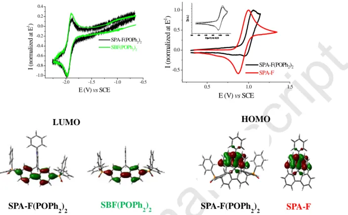
4 -2.0 -1.5 -1.0 -0.5 -1.0 -0.8 -0.6 -0.4 -0.2 0.0 0.2 0.4 I ( n o rm al ized at E 1 ) E (V) vs SCE SPA-F(POPh2)2 SBF(POPh2)2 0.5 1.0 1.5 -0.5 0.0 0.5 1.0 SPA-F(POPh2)2 SPA-F I (nor m al iz ed a t E 1 ) E (V) vs SCEFigure 1. Top. Normalized cyclic voltammograms of SPA-F(POPh2)2 (black lines), SBF(POPh2)2
(green lines) and SPA-F (red lines) in the cathodic (left, DMF + BuN4PF6 0.1 M) or the anodic (right,
CH2Cl2 + Bu4NPF6 0.2 M) range. Sweep-rate of 100 mV.s -1
, platinum disk (diameter 1 mm) working electrode. Inset in oxidation: first oxidation of SPA-F(POPh2)2 at 1V/s. Bottom: Frontier molecular orbitals obtained by DFT (B3LYP 6-31+G(d,p)).
SPA-F(POPh2)2 presents three successive reduction waves with maxima at -1.98, -2.50 and -2.79 V. This behaviour is very similar to the one recorded for SBF(POPh2)2 (-1.98, -2.48 and -2.80 V, see SI). For both compounds, the first reduction wave is reversible (E1/2: -1.94 V) (Figure 1, Top-left) whereas the second one is only partially reversible (see SI). The LUMO level obtained from E1/2 is hence evaluated at -2.46 eV for both compounds. Thus, the cathodic exploration indicates that the reduction of the two target molecules is fully governed by the acceptor part (diphenylphosphineoxide-fluorene)with no influence of the donor part (fluorene in SBF(POPh2)2 or phenylacridine in SPA-F(POPh2)2), indicating an electronic separation between the donor and the acceptor parts. This is in agreement with molecular modelling (B3LYP 6-31+G(d,p)), which shows that electronic delocalization of the LUMO, spread out on the fluorene bearing the diphenylphosphineoxide units, is very similar for the two compounds(Figure 1, Bottom-left).
In oxidation, SPA-F(POPh2)2 presents three successive oxidation waves with maxima at 1.06, 1.23 and 2.18 V (Figures in SI). The first oxidation processes is reversible only at high sweep-rate (see inset, Figure 1, Top-Right) (E1/2: 1.0 V). Compared to the oxidation of the model compound SPA-F, which presents, even at 100 mV/s, a first reversible oxidation wave (E1/2: 0.93 V), the oxidation of the phenylacridine unit in SPA-F(POPh2)2 is shifted by 70 mV in the anodic direction (Figure 1, Top-right). This indicates that, despite the separation of the donor and the acceptor units by the spiro bridge, the oxidation of the phenylacridine is
SBF(POPh 2)2 LUMO SPA-F(POPh 2)2 HOMO SPA-F(POPh 2)2 SPA-F
Revised
manuscript
5 influenced by the nature of the acceptor unit. Thus, in SPA-F(POPh2)2, the phenylacridine moiety is more difficult to oxidize than in SPA-F due to the presence of the electron poor bis(diphenylphosphineoxide)-fluorene unit. This leads to a shift of the HOMO levels evaluated from their respective E1/2 values at -5.33 eV for SPA-F and -5.40 eV for SPA-F(POPh2)2. Molecular modelling shows that the HOMO of both compounds is exclusively spread out on the phenylacridine moiety (Figure 1, Bottom-right). Thus, in SPA-F(POPh2)2, the localization of the HOMO and LUMO level is respectively identical to that of SPA-F and SBF(POPh2)2 model compounds.
Thanks to this rational design, the electrochemical energy gap of SPA-F(POPh2)2 calculated to 2.94 eV, from the HOMO and LUMO difference, is strongly contracted compared to that of SPA-F and SBF(POPh2)2 (3.39 and 3.54 eV respectively, Table 1 and figures in SI). This is a key point in the present design if we consider the need of being able to inject and transport both kind of charge carriers.
250 300 350 400 0 1x10⁴ 2x10⁴ 3x10⁴ 4x10⁴ ε ( L .mo l -1 .cm -1 ) l (nm) 400 450 500 550 600 0.0 0.5 1.0 nor m al is ed em is si on ( a. u. ) l (nm) SPA-F(POPh2)2 SPA-F SBF(POPh2)2 429449450
Figure 2. UV-Vis absorption spectra in cyclohexane at room temperature (left) and emission spectra at 77K in 2-Me-THF (λexc = 310 nm) normalized at the phosphorescence maxima (right) of SPA-F (red
lines), SBF(POPh2)2 (green lines) and SPA-F(POPh2)2 (black lines).
In UV-vis absorption spectroscopy, the three compounds present a short π-conjugation pathway with absorption in the near UV, below 330 nm (Figure 2, Left). SPA-F(POPh2)2 displays a broad band at 323 nm assigned in the light of Time-Dependent DFT to a transition with both orbitals centred on the fluorene (HOMO-1→ LUMO), see SI. Similarly, the highest band of SBF(POPh2)2 at 328 nm is due to a transition involving the two fluorene fragments (HOMO→ LUMO), see SI. SPA-F displays different characteristics with a small band at 309 nm and a long tail until 350 nm. These model compounds’ bands are also found in SPA-F(POPh2)2. It should finally be stressed that the calculated absorption spectrum shows that the first excited state corresponds to a forbidden HOMO-LUMO transition (f= 0.0001), not detectable experimentally, see SI. This important point in the present design finds its origin in the spatial separation of HOMO and LUMO levels (HOMO localized on the phenylacridine core and LUMO on the bis(diphenylphosphineoxide)-fluorene core) (Figure 1, bottom) leading to a through-space forbidden transition.[38] Thus, as the UV-vis absorption spectrum of SPA-F(POPh2)2 is not red shifted compared to the two model compounds, one can conclude that the electronic coupling between the electron-rich unit and the electron-poor unit is efficiently restrained, which is a key point in the present design.
The determination of the triplet state energy level ET of an organic molecule can be done at 77 K in a frozen matrix. First, the phosphorescent contributions of the two model compounds are well resolved, similar in shape but different in term of wavelengths. Indeed, SPA-F displays a
Revised
manuscript
6 first band at 429 nm and hence a very high ET of 2.89 eV, whereas SBF(POPh2)2 displays a red shifted first phosphorescent band at 449 nm providing a lower ET of 2.76 eV. The emission spectrum of SPA-F(POPh2)2 is also well resolved and presents a phosphorescence contribution, with a first band centred at 450 nm leading to a high ET of 2.76 eV (Figure 2, right). The emission from the T1 state is confirmed by the very long lifetime measured for these three compounds (τ =3.1, 5.6 and 2.7 s for SPA-F(POPh2)2, SPA-F and SBF(POPh2)2 respectively, Table 1). An important feature needs to be stressed out. Indeed, one can note that the phosphorescence contribution of SBF(POPh2)2 and that of SPA-F(POPh2)2 are almost superimposable, meaning that the ET is not influenced by the donor part and hence fully governed by the bis(diphenylphosphineoxide)-fluorene fragment. Thus, this design allows to reach a high ET material, suitable to host the FIrpic blue emitter. It should finally be mentioned that, at 77K, SPA-F(POPh2)2 does not present any fluorescence at shorter wavelengths as usually observed[44, 45] and only a phosphorescence contribution is observed. This is due to the very low quantum yield measured at room temperature (<0.01, assigned to the spatial HOMO/LUMO separation[38]), which should favoured the intersystem crossing between S1 and T1 leading to an intense phosphorescence contribution at 77 K.[46, 47]
Table 1. Selected electronic and physical data of SPA-F(POPh2)2, SPA-F and SBF(POPh2)2
SPA-F(POPh 2)2 SPA-F SBF(POPh2)2 l abs max [nm] a (ε ×104 [L.mol-1.cm-1]) 323 (2.0) 309 (2.4) 328 (0.65) lem phospho [nm]b 450 429 449 E T [eV] b,c 2.76 2.89 2.76 τ p [s] (lem [nm]) b 3.1 (450) 5.6 (429) 2.7 (449) Epox (V)d 1.06, 1.23, 2.18 1.0, 1.77, 2.20 1.79, 1.89 Epred (V)d -1.98, -2.50, -2.79 -2.56, -2.67 -1.98, -2.48, -2.80 HOMO (eV) -5.40e -5.33e -6.00f LUMO (eV) -2.46e -1.94f -2.46e ∆Eel (eV)g 2.94 3.39 3.54 µh+(cm2/V.s)h 8.2 × 10⁻⁶ 1 × 10⁻⁵ - µe-(cm2/V.s)h 2 × 10⁻⁴ - 6.9 × 10⁻⁵ Td (°C)i 474 286 382 Tg (°C)j 143 90 105 a. in cyclohexane; b. in 2-MeTHF at 77 K, l
exc = 310 nm; c. from first phosphorescence peak, d. vs SCE; e.
from E1/2; f. from Eonset (irreversible wave); g. ∆Eel= |HOMO-LUMO|; h. determined from SCLC devices
Revised
manuscript
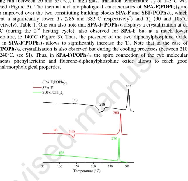
7 Before incorporation in electronic devices, the thermal properties have been studied by thermogravimetric analyses (TGA) and differential scanning calorimetry (DSC), Figure 3. Due to the presence of the rigid spiro bridge and bulky diphenylphosphine oxides, SPA-F(POPh2)2 presents very high thermal stability with a 5% mass loss occurring at Td ca 474°C
(See SI).As a complete mass loss occurs, this mass loss can be attributed to a sublimation process as previously observed for other π-conjugated systems.[30]
In DSC, during the 2nd heating run (between 20 and 350°C), a high glass transition temperature Tg of 143°C was
detected (Figure 3). The thermal and morphological characteristics of SPA-F(POPh2)2 are much improved over the two constituting building blocks SPA-Fand SBF(POPh2)2, which present a significantly lower Td (286 and 382°C respectively*) and Tg (90 and 105°C
respectively), Table 1. One can also note that SPA-F(POPh2)2 displays a crystallization at ca 218°C (during the 2nd heating cycle), also observed for SPA-F but at a much lower temperature, ie 140°C (Figure 3). Thus, the presence of the two diphenylphosphine oxide units in SPA-F(POPh2)2 allows to significantly increase the Tc. Note that in the case of
SBF(POPh2)2, crystallization is also observed but during the cooling processes (between 210 and 240°C, see SI). Thus, in SPA-F(POPh2)2, the spiro connection of the two molecular fragments phenylacridine and fluorene-diphenylphosphine oxide allows to reach good thermal/morphological properties.
Figure 3. DSC traces of, SPA-F(POPh2)2 (top), SPA-F(middle) and SBF(POPh2)2 (bottom)
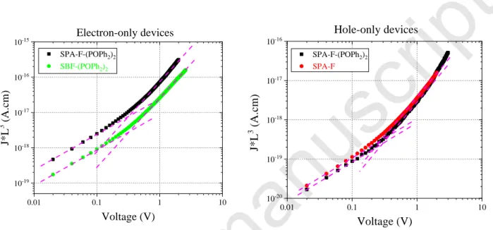
As mentioned previously, in SL-PHOLED, because of the device simplification and therefore the removal of the charge carrier transporting and blocking interlayers, proper and balanced hole and electron mobilities are required to promote effective recombination of carriers in the active layer. Therefore, charge transport properties of the host material must be investigated. Since the PhOLED device consists of a vertical stack, we used space charge limited current (SCLC) devices to measure the out-of-plane hole and electron mobilities, thanks to elaboration of hole-only and electron-only devices, respectively (see SI for composition and elaboration details). In order to rationalize the charge carrier mobilities in SPA-F(POPh2)2, we also investigated the hole mobility of SPA-F and the electron mobility of SBF(POPh2)2 (Table 1). SPA-F exhibits a moderate hole mobility of 1×10⁻⁵ cm2/V.s, while SBF(POPh2)2
50 100 150 200 250 300 Temperature (°C) SPA-F(POPh2)2 SPA-F SBF(POPh2)2 143 218 303 90 140 280 105 276
Revised
manuscript
8 has shown a similar range electron mobility of 6.9×10⁻⁵ cm2/V.s. It is worth noting that SPA-F(POPh2)2 combines the charge carrier mobilities of the two model compounds. Indeed, the hole mobility has been measured to be 8.2×10⁻⁶ cm2/V.s, only 1.2 times less than that of the SPA-F hole transporting model compound, while an electron mobility of 2×10⁻⁴ cm2/V.s, 3 times greater than that of SBF(POPh2)2 was measured. This feature highlights the efficient approach used in the chemical design of SPA-F(POPh2)2, which provides a very rational combination of the model compounds properties (electrochemical, optical and charge transport). Finally, mobilities in SPA-F(POPh2)2 are rather well balanced with an electron mobility only 20 times higher than the hole mobility.
Figure 4. Thickness-scaled current voltage characteristics of (left) SBF-(POPh2)2 and SPA-F(POPh2)2
electron-only SCLC devices and of (right) SPA-F(POPh2)2 and SPA-F hole-only SCLC devices. The dotted-lines indicate the Ohmic regime and the continuous ones the SCLC regime.
SPA-F(POPh2)2 was finally incorporated as host in green and blue SL-PhOLEDs using as emitter either Ir(ppy)3 or FIrpic respectively (average values in Table 2 and best performance in Figure 5). The SL-PhOLED architecture is the following: ITO/PEDOT:PSS (40 nm)/EML (Host+Guest 10 % wt) (100 nm)/LiF (1.2 nm)/Al (100 nm). It is important to stress that the anode is not a neat ITO but a ITO/PEDOT:PSS anode as classically used to induce a better organization of the interface and a decrease of the anode work function.[48] The green SL-PhOLED displays a high performance with a maximal external quantum efficiency (EQE) of 15.6%, and corresponding current efficiency (CE) of 52.9 cd/A and power efficiency (PE) of 52 lm/W at 0.04 mA/cm² (average values, Table 2). The best device reaches a maximum luminance of 38970 cd.m-2 at 180 mA/cm2 (21.7 cd/A) showing a high performance and good stability at high current density. In 2015, our group has reported an efficient bipolar host for green SL-PhOLED, possessing an identical device architecture than that exposed herein. [26]
This green SL-PhOLED displayed a high maximum EQE of 13.2 % (CE= 45.8 Cd/A , PE 49.6 lm/W, maximum luminance of 20000 cd.m-2 ). However, the host material presented a low ET of 2.64 eV, being not suitable for blue SL-PhOLED applications. Thus, SPA-F(POPh2)2 investigated in this work not only exceeds this previous green SL-PhOLED performance but can also be used as host for blue PhOLEDs due to its high ET of 2.75 eV (see below).
Due to their different ET (2.42 eV for Ir(ppy)3 and 2.62 eV for FIrpic) and their different HOMO/LUMO energy levels,[47] it is far more difficult to host a blue phosphor than a green phosphor. However, in the present case, the blue SL-PHOLED using FIrpic as emitter also
0.01 0.1 1 10 10-19 10-18 10-17 10-16 10-15 SPA-F-(POPh2)2 SBF-(POPh2)2 J* L 3 ( A. cm ) Voltage (V) Electron-only devices 0.01 0.1 1 10 10-20 10-19 10-18 10-17 10-16 SPA-F-(POPh2)2 SPA-F Hole-only devices J* L 3 ( A. cm ) Voltage (V)
Revised
manuscript
9 displays excellent performances. Indeed, a high EQE of 17.6% with CE of 37.8 cd/A and PE of 37.1 lm/W were recorded at 0.04 mA/cm² (average values, Table 2). At 10 mA/cm², the performance remains high, 12.6% (CE = 27.0 cd/A and PE = 14.6 lm/W), showing the stability of the host under device working conditions. It is important to mention that at the high luminance of 5000 cd/m2, the device still displays a high EQE of 12.3% and at 10000 cd/m2 the EQE is still recorded at 10.9 % (see SI).
For both devices, the threshold voltage (Von) is very low, 2.3 V for the green PhOLED and 2.5 V for the blue PhOLED, signing an efficient charge injection in the EML. This is due to the good matching between the HOMO level of SPA-F(POPh2)2 (-5.40 eV) and ITO/PEDOT-PSS (-5.1 eV), which facilitates the hole injection.
All the devices exhibited identical green or blue emission arising from their corresponding Iridium complex, showing an efficient energy transfer cascade (see electroluminescent spectra in SI). To conclude, it should be precise that versatile hosts, which can be efficiently used in both green and blue SL-PhOLEDs are very rarely reported in literature. For example, in 2017, Zhao, Xie and their coworkers have reported a versatile host material for SL-PhOLEDs constructed on the judicious association of benzimidazole and carbazole units. If the performance of green SL-PhOLEDs were reported to be high (EQE of 14.6%), those of blue devices only reached ca 10%.[19]
Von (V) EQE (%) CE (cd/A) PE (lm/W) EQE (%) CE (cd/A) PE (lm/W) Luminance (cd/m2)
Green PhOLEDs(10% Ir(ppy)3)
At 10 mA/cm2 Max (at J (mA/cm2)) At J (mA/cm2) SPA-F(POPh2)2 2.3 10.9 37.1 17.7 15.6 (0.04) 52.9 (0.04) 52.0 (0.04) 38970 (180) SBF(POPh2)2 2.8 4.6 12.1 5.3 5.2 (50) 14.3 (50) 5.0 (50) 11620 (120) SPA-F 5.9 0.1 0.3 0.1 0.2 (25) 0.4 (24) 0.1 (21) 96 (90)
Blue PhOLEDs (10% FIrpic)
SPA-F(POPh2)2 2.5 12.6 27.0 14.6 17.6 (0.04) 37.8 (0.04) 37.1 (0.04) 11400 (50) SBF(POPh2)2 4.1 0.35 0.42 0.16 0.6 (44) 0.7 (36) 0.2 (22) 152.9 (50)
Revised
manuscript
10
Table 2. Average performance of SL-PhOLEDs using SPA-F(POPh2)2, SBF(POPh2)2 or SPA-F as host material and 10% Ir(ppy)3 or FIrpic as green or blue emitter respectively. Device structure:
ITO/PEDOT:PSS (40 nm)/host + dopant (100 nm)/LiF (1.2 nm)/Al (100 nm).
0 10 20 30 40
30 60 90
Current Density (mA/cm2)
C u rr ent E ff ic ie nc y ( cd /A ) 0 10 20 30 40 50 60 P o w er E ff ici en cy ( lm /W ) 0 10 20 30 40 50 0 5 10 15 20 25 30 35 40 P ow er e ff ic ie nc y ( lm /W )
Current density (mA/cm2)
0 5 10 15 20 25 30 35 40 C ur re nt e ff ic ie nc y ( cd /A )
Figure 5: Current (cd/A) and power (lm/W) efficiency vs current density (mA/cm2) for the best green (Left) and blue (Right) SL-PhOLEDs using SPA-F(POPh2)2 as host
In order to shed light on the efficiency of the present bipolar host, we have investigated benchmark devices using the two model compounds SPA-F and SBF(POPh2)2 as host (Table 2 and SI). First, SL-PhOLEDs using SPA-F as host display very low performance with an EQE below 0.5% for green PhOLEDs. Thus, from a chemical design point of view, the acridine is not directly responsible of the high performance of SPA-F(POPh2)2-based PhOLED.
Despite significant better performance than that of SPA-F, green SL-PhOLEDs using SBF(POPh2)2 as host displays modest performance with a maximum EQE of 5.2 % (corresponding CE of 14.3 cd/A and PE of 5.0 lm/W, table 2), more than three times lower than that of SPA-F(POPh2)2.
For the blue SL-PhOLEDs, the efficiency of the model compounds is worst. Indeed, the performance of blue SL-PhOLEDs using SPA-F as host is too low to be measured and that using SBF(POPh2)2 also displays very bad performances with an EQE <1%. Due to its deep HOMO level (-6.0 eV), SL-PhOLED using SBF(POPh2)2 displays a high Von of 4.1 V.
Thus, one can note that the two model compounds display very low performances when incorporated as host in blue SL-PhOLED whereas their combination in SPA-F(POPh2)2 leads to high performance PhOLEDs. The performances difference observed in model compounds compared with that of SPA-F(POPh2)2 is probably due to the energy levels adjustment, made from the association of the two molecular fragments, phenylacridine and 2,7-bis(diphenylphosphineoxide)-fluorene. Indeed, as observed in cyclic voltammetry, SPA-F(POPh2)2 roughly exhibits the HOMO and LUMO energy levels of SPA-F and
SBF(POPh2)2, respectively. In return, as shown in Table 1, the two model compounds, that could be, electronically speaking, considered as an incomplete half of the SPA-F(POPh2)2 molecule, display either a HOMO or a LUMO level that does probably not allow efficient charge carrier injections in the device architecture used in this work. Thus, if considering the PEDOT-PSS work function to be around -4.9/5.2 eV,[49, 50] it seems pretty obvious that hole injection in the SBF(POPh2)2 electron model compound will encounter a high barrier injection of at least 0.7-0.8 eV (HOMO = -6.0 eV). The same holds true regarding the electron injection in the SPA-F hole model compound that shows a significantly lower electron affinity (LUMO= -1.94 eV) than the diphenylphosphineoxide-functionalized molecules, SPA-F(POPh2)2 and SBF(POPh2)2.
Revised
manuscript
11 Conclusion
In this work, we have designed and synthesized, via an efficient approach, a high efficiency host material for green and more importantly for blue Single-Layer PhOLEDs. This host is using a chemical architecture based on the conjugation disruption, thanks to the spiro-connection, between the electron-rich phenylacridine moiety and the fluorene bearing the two phosphine oxide electron-deficient units. By comparing this new molecular host with the two model compounds constituted of each unit, we highlight that its optoelectronic properties correspond to a rational combination of the properties of the two model compounds. Thus, in addition to a high ET (2.76 eV) and adequate HOMO/LUMO energy levels (-5.40 eV/-2.46 eV), the key point in the design of this host is its good balance between suitable hole and electron mobilities, which leads to a high-performance blue SL-PhOLED with an EQE of 17.6% (CE= 37.8 cd/A and PE = 37.1 lm/W) and a low Von of 2.5 V. This high performance is among the highest reported to date and shows that the molecular design of the present host fulfils the criteria required for high efficiency SL-PhOLED. The green SL-PhOLED is also among the most efficient reported to date. As simplifying the device structure can be a central feature in the future of OLEDs, designing highly efficient semi-conductors for this purpose is an important step.
Supporting Information
Supporting Information is available from the Wiley Online Library or from the author.
Acknowledgments
The authors would like to thank the CINES (Montpellier N° 2018-A0040805032) for computing time, the ANR (n°14-CE05-0024) and the Region Bretagne (DIADEM project) for PhD grants (LJS and FL) and post-doctoral position (CQ), the CDFIX and CRMPO (Rennes). We would like to highly thank Dr Eric Le Fur (Rennes) for TGA analyses, Dr Franck Camerel for his help in DSC measurements and Dr Emmanuel Jacques (Rennes) for fruitful discussions about charge carrier mobilities.
Received: ((will be filled in by the editorial staff)) Published online: ((will be filled in by the editorial staff))
References
[1]M. A. Baldo, D. F. O'Brien, Y. You, A. Shoustikov, S. Sibley, M. E. Thompson, S. R. Forrest, Nature 1998, 395, 151-154.
[2]Y. Tao, C. Yang, J. Qin, Chem. Soc. Rev. 2011, 40, 2943-2970.
[3]Y. Im, S. Y. Byun, J. H. Kim, D. R. Lee, C. S. Oh, K. S. Yook, J. Y. Lee, Adv.
Funct. Mater. 2017, 27, 1603007.
[4]S. Lee, B. Kim, H. Jung, H. Shin, H. Lee, J. Lee, J. Park, Dyes Pigm. 2017, 136, 255-261.
[5]L. Sicard, H.-C. Li, Q. Wang, X.-Y. Liu, O. Jeannin, J. Rault-Berthelot, L.-S. Liao, Z.-Q. Jiang, C. Poriel, Angew. Chem. Int. Ed. 2019, 58, 3848–3853.
[6]A. Maheshwaran, V. G. Sree, H.-Y. Park, H. Kim, S. H. Han, J. Y. Lee, S.-H. Jin,
Adv. Funct. Mater. 2018, 28, 1802945-1802951.
Revised
manuscript
12 [8]J.-J. Huang, Y.-H. Hung, P.-L. Ting, Y.-N. Tsai, H.-J. Gao, T.-L. Chiu, J.-H. Lee, C.-L. Chen, P.-T. Chou, M.-k. Leung, Org. Lett. 2016, 18, 672-675.
[9]L. Ding, S.-C. Dong, Z.-Q. Jiang, H. Chen, L. S. Liao, Adv. Funct. Mater. 2015, 25, 645-650.
[10]L.-S. Cui, Y.-M. Xie, Y.-K. Wang, C. Zhong, Y.-L. Deng, X.-Y. Liu, Z.-Q. Jiang, L.-S. Liao, Adv. Mater. 2015, 27, 4213-4217.
[11]K. Udagawa, H. Sasabe, C. Cai, J. Kido, Adv. Mater. 2014, 26, 5062-5066. [12]J.-K. Bin, N.-S. Cho, J.-I. Hong, Adv. Mater. 2012, 24, 2911-2915.
[13]C.-W. Lee, J. Y. Lee, Chem. Commun. 2013, 49, 1446-1448.
[14]J. H. Kim, S.-H. Hwang, W. Song, J. Y. Lee, Dyes Pigm. 2015, 122, 103-108. [15]Z. Liu, M. G. Helander, Z. Wang, Z. Lu, Org. Electron. 2009, 10, 1146-1151. [16]W.-Y. Hung, T.-C. Tsai, S.-Y. Ku, L.-C. Chi, K.-T. Wong, Phys. Chem. Chem.
Phys. 2008, 10, 5822-5825.
[17]X. Qiao, Y. Tao, Q. Wang, D. Ma, C. Yang, L. Wang, J. Qin, F. Wang, J. Appl.
Phys. 2010, 108, 034508.
[18]J. Ye, Z. Chen, K. Wang, F. An, Y. Yuan, W. Chen, Q. Yang, X. Zhang, C.-S. Lee, Chem. Eur. J. 2014, 20, 13762-13769.
[19]C. Zang, X. Peng, H. Wang, Z. Yu, L. Zhang, W. Xie, H. Zhao, Org. Electron. 2017, 50, 106-114.
[20]D. Tomkute-Luksiene, J. Keruckas, T. Malinauskas, J. Simokaitiene, V. Getautis, J. V. Grazulevicius, D. Volyniuk, V. Cherpak, P. Stakhira, V. Yashchuk, V. Kosach, G. Luka, J. Sidaravicius, Dyes Pigm. 2013, 96, 278-286.
[21]C.-H. Chen, W.-S. Huang, M.-Y. Lai, W.-C. Tsao, J. T. Lin, Y.-H. Wu, T.-H. Ke, L.-Y. Chen, C.-C. Wu, Adv. Funct. Mat. 2009, 19, 2661-2670.
[22]M.-Y. Lai, C.-H. Chen, W.-S. Huang, J. T. Lin, T.-H. Ke, L.-Y. Chen, M.-H. Tsai, C.-C. Wu, Angew. Chem. Int. Ed. 2008, 47, 581-585.
[23]Y. Liu, L.-S. Cui, M.-F. Xu, X.-B. Shi, D.-Y. Zhou, Z.-K. Wang, Z.-Q. Jiang, L. S. Liao, J. Mater. Chem. C 2014, 2, 2488-2495.
[24]W.-Y. Hung, T.-C. Wang, H.-C. Chiu, H.-F. Chen, K.-T. Wong, Phys. Chem.
Chem. Phys. 2010, 12, 10685-10687.
[25]B. Huang, W. Jiang, J. Tang, X. Ban, R. Zhu, H. Xu, W. Yang, Y. Sun, Dyes
Pigm. 2014, 101, 9-14.
[26]S. Thiery, D. Tondelier, B. Geffroy, E. Jacques, M. Robin, R. Métivier, O. Jeannin, J. Rault-Berthelot, C. Poriel, Org. Lett. 2015, 17, 4682-4685.
[27]J. P. J. Markham, S.-C. Lo, S. W. Magennis, P. L. Burn, I. D. W. Samuel, Appl.
Phys. Lett. 2002, 80, 2645-2647.
[28]Z. Wu, Z. Yang, K. Xue, C. Fei, F. Wang, M. Yan, H. Zhang, D. Ma, W. Huang,
RSC Adv. 2018, 8, 11255-11261.
[29]W. Jiang, L. Duan, D. Zhang, G. Dong, L. Wang, Y. Qiu, J. Mater. Chem. 2010,
20, 6131-6137.
[30]H.-H. Chang, W.-S. Tsai, C.-P. Chang, N.-P. Chen, K.-T. Wong, W.-Y. Hung, S.-W. Chen, Org. Electron. 2011, 12, 2025-2032.
[31]F.-M. Hsu, L.-J. Chien, K.-T. Chen, Y.-Z. Li, S.-W. Liu, Org. Electron. 2014, 15, 3327-3332.
[32]Y. Yin, X. Wen, J. Yu, L. Zhang, W. Xie, IEEE Photonics Technology Letters 2013, 25, 1041-1135.
[33]Y. Yin, X. Piao, Y. Wang, J. Liu, K. Xu, W. Xie, App. Phys. Lett. 2012, 101, 063306.
[34]C. Fan, Y. Li, C. Yang, H. Wu, J. Qin, Y. Cao, Chem. Mater. 2012, 24, 4581-4587.
Revised
manuscript
13 [35]K. H. Yeoh, N. A. Talik, T. J. Whicher, C. Y. B. Ng, J. Phys. D: Appl. Phys. 2014, 47, 205103-.
[36]S. E. Jang, J. Y. Lee, J. Lumin. 2011, 131, 2788-2791. [37]K. S. Yook, J. Y. Lee, Adv. Mater. 2012, 24, 3169-3190.
[38]M. Romain, D. Tondelier, O. Jeannin, B. Geffroy, J. Rault-Berthelot, C. Poriel, J.
Mater. Chem. C 2015, 3, 9701-97014.
[39]M. Romain, D. Tondelier, B. Geffroy, O. Jeannin, E. Jacques, J. Rault-Berthelot, C. Poriel, Chem. Eur. J. 2015, 21, 9426–9439.
[40]S. E. Jang, C. W. Joo, J. Y. Lee, Thin Solid Films 2010, 906-910. [41]C. Poriel, J. Rault-Berthelot, Acc. Chem. Res. 2018, 51, 1818-1830.
[42]C. Poriel, F. Barrière, J. Rault - Berthelot, D. Thirion, Chem. Eur. J. 2019, 25, 7740-7748.
[43]S. E. Jang, K. S. Yook, J. Y. Lee, Org. Electron. 2010, 11, 1154-1157.
[44]C. Quinton, S. Thiery, O. Jeannin, D. Tondelier, B. Geffroy, E. Jacques, J. Rault-Berthelot, C. Poriel, ACS Appl. Mater. Interfaces 2017, 9, 6194–6206.
[45]C. Poriel, J. Rault-Berthelot, J. Mater. Chem. C 2017, 5, 3869-3897
[46]C. Poriel, J. Rault-Berthelot, S. Thiery, C. Quinton, O. Jeannin, U. Biapo, B. Geffroy, D. Tondelier, Chem. Eur. J. 2016, 22, 17930-17935.
[47]S. Thiery, D. Tondelier, C. Declairieux, B. Geffroy, O. Jeannin, R. Métivier, J. Rault-Berthelot, C. Poriel, J. Phys. Chem. C 2015, 119, 5790–5805.
[48]T.-C. Li, R.-C. Chang, Int. J. of Precis. Eng. and Manuf.-Green Tech. 2014, 329-333.
[49]E. L. Ratcliff, R. C. Bakus Ii, G. C. Welch, T. S. van der Poll, A. Garcia, S. R. Cowan, B. A. MacLeod, D. S. Ginley, G. C. Bazan, D. C. Olson, J. Mater. Chem. C 2013, 1, 6223-6234.