HAL Id: hal-02128204
https://hal.archives-ouvertes.fr/hal-02128204
Submitted on 3 Dec 2020HAL is a multi-disciplinary open access archive for the deposit and dissemination of sci-entific research documents, whether they are pub-lished or not. The documents may come from teaching and research institutions in France or abroad, or from public or private research centers.
L’archive ouverte pluridisciplinaire HAL, est destinée au dépôt et à la diffusion de documents scientifiques de niveau recherche, publiés ou non, émanant des établissements d’enseignement et de recherche français ou étrangers, des laboratoires publics ou privés.
Improved Dielectric Properties in
Polypropylene/Poly(vinylidene fluoride) Binary Blends
Containing Boron Nitride Nanosheets: Toward
High-Voltage Current Application
Benhui Fan, Mingyu Zhou, Chong Zhang, Jinkai Yuan, Delong He, Yu Liu,
Paul Haghi-Ashtiani, Jinbo Bai
To cite this version:
Benhui Fan, Mingyu Zhou, Chong Zhang, Jinkai Yuan, Delong He, et al.. Improved Dielectric Proper-ties in Polypropylene/Poly(vinylidene fluoride) Binary Blends Containing Boron Nitride Nanosheets: Toward High-Voltage Current Application. Journal of Physical Chemistry C, American Chemical Society, 2019, 123 (18), pp.11993-12000. �10.1021/acs.jpcc.9b02271�. �hal-02128204�
Improved Dielectric Properties in Polypropylene/Poly (vinylidene fluoride) Binary Blends Containing Boron Nitride Nanosheets (BNNS): towards High Voltage Current Application
Benhui Fan1, Mingyu Zhou2, Chong Zhang3, Jinkai Yuan4, Delong He1, Yu Liu1, Paul Haghi-Ashtiani1
and Jinbo Bai1*
1Laboratoire Mécanique des Sols, Structures et Matériaux (MSSMat), CNRS UMR 8579,
CentraleSupélec, Université Paris Saclay, 8-10 Rue Joliot-Curie, 91190, Gif-sur-Yvette, France
2Global Energy Interconnection Research Institute Europe GmbH, Kantstr.162, 10623, Berlin,
Germany
3State Key Laboratory of Advanced Transmission Technology, Global Energy Interconnection
Research Institute, Beijing 102211, People’s Republic of China
4Centre de Recherche Paul Pascal (CRPP) UMR 5031, 115 Av Schweitzer, 33600 Pessac, France
*Corresponding author: Jinbo BAI, [email protected]
Abstract
Binary blends of polypropylene (PP) and poly (vinylidene fluoride) (PVDF) are often hard to process by extrusion due to the poor compatibility between the two semi-crystalline polymers. Considering the fast crystallization during the stretching at room temperature, PVDF products with low molecular weight was selected in this study and consequently it presented improved compatibility with PP which favored to extrude and stretch the binary blending film (50-50 weight ratio) into micro-metric thickness. The obtained binary blending film had reasonable dielectric constant over 3.6, low dielectric loss of 0.54% and high breakdown strength of 439 MV/m. Furthermore, boron nitride nanosheets (BNNS) obtained by liquid exfoliation were introduced into PP/PVDF binary blends and the composite film displayed further reduced dielectric loss of 0.41% and increased breakdown strength of 478 MV/m. In addition, the composite film with BNNS also had high Young’s modulus and tensile strength. The enhanced dielectric and mechanical properties made PP/PVDF (50-50)/BNNS 5% display potential values in the application of film capacitors for high voltage direct current (HVDC) systems.
Introduction
The development of extrusion-processed polymer based materials with high dielectric performances has always been attractive for film capacitors.1-2 As a kind of capacitors with a capacitance ranging from nF to mF in the order of magnitude, film capacitors have a variety of applications in such as electronic circuits, analog filter networks and resonant circuits, etc..3 Especially, flexible films with improved dielectric constant and low dielectric loss are extremely appealing for the dielectrics in modern high voltage direct current (HVDC) systems, one of the main strategies in the future for a long distance electricity transmission (over 1500 km) because of its high efficiency and low energy loss.4 The current state-of-the-art technology uses metallized biaxially oriented polypropylene (BOPP) with the dielectric constant of ~2.2 and the dielectric loss of ~0.2%.5 But the shortage of BOPP is its low dielectric constant which is hard to meet the strict requirement of dielectrics used in HVDC systems: improved dielectric constant (ε’ of ~3.5-4 at 1000 Hz), extremely low dielectric loss (tan δ of <0.5% at 1000 Hz) and high dielectric breakdown strength (Eb of ~450 MV/m).
Actually, most of the polymers are with low dielectric constant (less than 3 at 1000 Hz), except poly (vinylidene fluoride) (PVDF) and its copolymers whose dielectric constants are usually over 9.6, 7 But one of the obvious disadvantages of PVDF series polymers is their high dielectric loss (over 2.2% at 1000 Hz) caused by the polarity from C-F bonds 7 which largely limits its application. An ideal situation is to find some methods which can effectively combine low dielectric loss of PP and high dielectric constant of PVDF. Therefore, based on the industrial manufacturing, fabricating PP/PVDF binary blending films by extrusion seems to be attractive for realizing the objective dielectric performances required by HVDC systems.
However, as two kinds of semi-crystalline polymers, PP and PVDF usually have different flow induced crystallization behaviors during the stretching from the molten stage. The mismatch in the crystallization during the solidification often causes the detachment and porosity in the binary blending film. Meanwhile, PVDF is a kind of polymer with high surface energy which also brings difficulty to robustly adhere with PP. Thus, the binary blending of PP and PVDF usually suffers the poor compatibility and consequently, the film with micro-scale thickness is hard to achieve by extrusion. Some works try to improve the compatibility between PP and PVDF by the reactive blending process like the introduction of copolymers such as polypropylene grafted maleic (PP-g-MA) 8 or styrene maleic anhydride copolymer (SAM). 9 The compatibility has been reported to improve but it has to be pointed out that the blends of PP and PVDF with a certain copolymer may have the risk of increasing dielectric loss, because these copolymers usually have reactive segments with the polarity. For example, in the case of PP/PVDF/SAM ternary blends (the volume fractions of PP and PVDF is 80-20 and the weight fractions of SAM is 3%), the dielectric loss at 1000 Hz is about 2%. The case of PP-g-MA blending with PP and PVDF also has the problem of an increased dielectric loss. Hence, it is necessary to find another method to improve the compatibility between PP and PVDF and simultaneously keep the dielectric loss at low level.
As mentioned before, the mismatch in the crystallization is one of the reasons for the poor compatibility between PP10 and PVDF11. If possible to modify the flow induced crystallization of either PP or PVDF, the compatibility between two may be improved and their binary blending film with micro-metric thickness has the possibility to obtain. The flow induced crystallization of a
thermoplastic polymer is largely associated with the molecular weight and distribution.12, 13 Generally, a kinetic pathway composing coil (melt) → still segment (helix) → precursor → crystal is proposed to describe nucleation under the flow.10 Polymeric segments with lower molecular weight are easy to relax and the crystalline regions usually show the transverse lamellae in growth direction, which is known as the “row structure”.13 These row structures may influence the nucleation of the second polymer and change the crystallization. Based on this crystallization scenario, PVDF pellets with lower molecular weight are selected in this study to prepare the binary blending film with PP.
In addition, the crystallization of a polymer is also largely influenced by the nano-confinement which affects crystal orientations, crystallinities and structures. Inorganic fillers have been widely reported with the function of altering immiscible polymer blending by achieving confinements of controlled size and morphology.12 Thus, hexagonal boron nitride (BN) has been selected as reinforcing charges to prepare PP/PVDF based composite in order to further improve compatibility between PVDF and PP. As a kind of platelet-like particles with high thermal conductivity: the in-plane thermal conductivity of hexagonal BN is about 600 W/(mK) and the out-of-plane conductivity is 30 W/(mK).14-16 Moreover, as a type of insulating ceramics, BN is with large band gap of 5.2 eV, reasonable dielectric constant of about 4 and extremely high breakdown strength of around 800 MV/m.17 Especially, according to currently reported works, the breakdown voltage of BN can be further promoted by decreasing the thickness of BN sheet down to few layers, known as BN nanosheets (BNNS) obtained by the long-term liquid exfoliation.17, 18 Therefore, using BNNS to prepare the composite may potentially achieve better adhesion with PP and PVDF by altering nucleation of polymer during the flow so as to improve the quality of the binary blending film. In the following parts of this study, the dielectric and mechanical properties of PP/PVDF binary blending film and the composite film reinforced by BNNS will be discussed based on the crystallization and micro-morphology.
Experimental Section
Materials: PP pellets were provided by Borealis, Belgium. PVDF pellets (Mn~71,000 and
Mw~180,000) and dimethylformamide (DMF) solvent were purchased from Sigma Aldrich. Hexagonal BN with platelet’s thickness of 1-2 μm was purchased from Merch KGaA, Germany. BNNS was prepared by the long-term liquid exfoliation of BN platelets in an ultrasound bath according to the reported way.19, 20 Before the experiments, all the products were stored in an oven at 80 oC overnight.
Preparation: for preparing the binary blending film with 50-50 weight ratios, PP and PVDF pellets
were put into a micro-extruder/compounder (Micro 5 cc Twin Screw Compounder, DSM) and mixed at 230 °C for 20 min by twin strews with the speed of 60 rpm. The extrusion and stretching were conducted by the rolling system (Xplore) at room temperature. For preparing the PP/PVDF (50-50)/BNNS composite film, the weight fractions of BNNS were 5% and the preparation was divided into two steps: in the first step, the mixture of PVDF and BNNS was fabricated by solution casting to avoid the agglomerates of BNNS as far as possible: BNNS was dispersed in DMF solvent by ultrasonication for 30 min and then PVDF pellets were put into the suspension of BNNS/DMF and mixed by magnetic stirring at 70 oC for 1 h. The mixture of BNNS and PVDF was dried at 80 oC
small pieces were blended with PP pellets in the microcompounder and then stretched. The processing conditions were the same as the case of the binary blends. A schematic diagram is presented in Figure 1 to describe the whole preparation.
Figure 1 Schematic diagram for describing the film prepared by the extrusion and stretching
process. (MD: machine direction, parallel to the stretching direction. TD: transverse direction, vertical to the stretching direction)
Characterizations: The morphology of film’s cross-section was observed by scanning electron
microscope (SEM) (ZEISS, LEO 1530 Gemini). The samples were broken after impregnated in liquid nitrogen for 5 min. The fractured surfaces were coated by a thin layer of gold to increase the surface conductivity. Transmission electron microscope (TEM) imaging was performed by a Titan3 G2 with a field emission gun (XFEG) operating at an accelerating voltage of 200 kV. Energy Dispersive X-ray spectroscopy (EDX) was carried out at 200 kV in scanning transmission electron microscope (STEM) mode. All the images were acquired by high-angle annular dark-field detector (HAADF). The EDX mapping was acquired for 10 min.
X-ray diffraction (XRD) (D2 Phaser X-ray Powder Diffraction, Bruker) was used to study the crystalline behavior of the polymers and composites. The measure range of 2θ was from 10 to 30o in 2500 s.
Frequency dependence of dielectric properties was measured by Solartron modulab XM at room temperature with the frequency range from 10-1 to 105 Hz. The surface area of the sample was 10
mm × 10 mm. Silver pastes were applied on both faces of the sample for reducing contacting resistances. The tested samples were considered as a plane capacitor and described by parallel resistor-capacitor (RC) circuit systems.
Breakdown strength of the film was measured by PolyK Ferroelectric Polarization Loop & Dielectric Breakdown Test System. The thickness of the sample was measured by thickness gauge way on an iron plate (Surfix Pro, PHYNIX) and the thickness range of each film was from 15-25 μm. During the measurement, the increasing rate of voltage was set as 200 V/s. The measurements were carried out at room temperature in the silicon oil for avoiding the corona discharging in air. At least 10 breakdown trials were performed for each film to conduct Weibull failure analysis:21
P(E) = 1 − exp [−(Eα-)β]
where P(E) was the cumulative probability of electric failure; Eb was the measured breakdown
sample to breakdown; and shape parameter β evaluated the scatter of data.
Mechanical properties of the film in two processing directions, MD (mechanical direction) and TD (transverse direction) were characterized by Instron 5544 with the stretching speed of 1 mm/s. The samples for the mechanical properties were cut by a standard mold with the width of 3.15 mm. Each film was measured at five times to obtain the average values. Young’s modulus was obtained by measuring the slope of the axial stress-stain curves in the elastic region. The tensile strength was the maximum value of the stress in the stress-strain curves.
Results and discussions
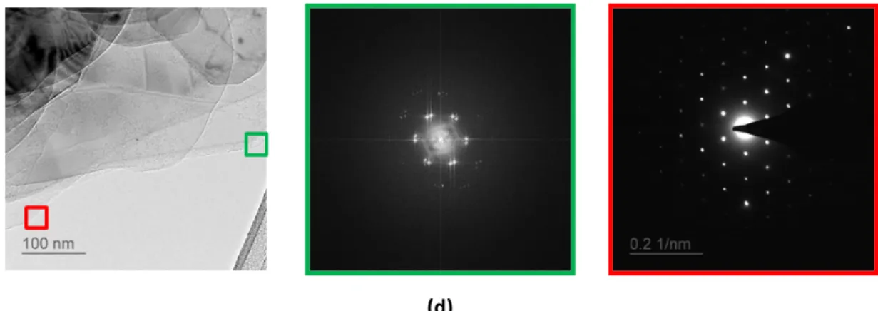
Morphology of BNNS characterized by TEM is shown in Figure 2 (a). It can be found that the thickness of BNNS is with several layers. Figure 2 (b) shows the high-magnification TEM images of BNNS. The ultra-flat surface with clear regular atoms lines has been partly destroyed, which may be caused by two reasons: One possibility is from the long-term ultrasonic exfoliation and the other is from the high electric field during the characterization (200 kV is used in TEM). To study the chemical composition of BNNS, the EDX mapping in STEM mode has been conducted and the results are shown in Figure 2 (C). It can be found that nitride and boron are detected in these regions as presented by green and red points, respectively. These boron and nitride points are distributed homogeneously without obvious voids. Thus, it can be thought that the destroyed area on some surface of the nanosheet as presented in Figure 2 (b) is still with the boron nitride composition and the chemical composition has no obvious change. After ultrasonication, some BNNS have been exfoliated to the monolayer’s state. Two zones are chosen to obtain the selected area electron diffraction (SEAD) patterns, as shown in Figure 2 (d). A typical hexagon pattern has been observed in the red rectangular area, which indicates the monolayer structure of BNNS. Another area in green rectangular shows a triple hexagon pattern which infers the three-layered structure of BNNs.
(a) (b)
(d)
Figure 2 (a) and (b): TEM images of BNNS sample. (c): STEM image of BNNS sample with EDX on
nitride, boron and carbon chemical elements analysis (d): SAED patterns of BNNS: there are two places, the red one and the green one in the left image which are corresponding to the SAED patterns with red and green edges.
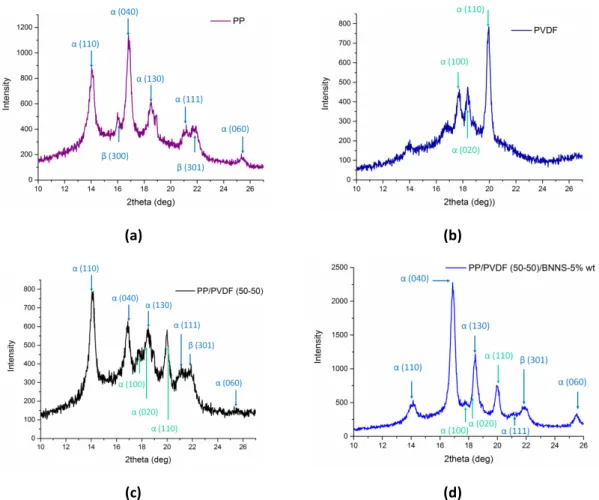
XRD patterns for PP, PVDF, the binary blending and the composite film charged by BNNS are presented in Figure 3. As presented in Figure 3 (a), it can be found that for the neat PP film, there are two crystalline phases:22 α phase with the typical peaks at 2θ = 14.1 o (110), 16.8o (040), 18.5o
(130), 21.2o (111) and 25.5o (060) and β phase with the typical peaks at 2θ= 16.1o (300) and 21.8o
(301). For the neat PVDF film,23, 24 as presented in Figure 3 (b), the crystallites of XRD pattern only display α phase with the typical peaks at 2θ = 17.8o, 18.2o and 19.8o. Especially, the peaks of (100)
and (020) have similar diffraction intensities. This is a bit different from the crystalline patterns of PVDF with higher molecular weight 25 (such as the products of PVDF 761 from Arkema with the Mw ~ 441,000), where these two peaks of (100) and (020) are with different diffraction intensities. As mentioned, polymeric segments with lower molecular weight generally tend to form the crystallites with row structures. The similar intensities at two α peaks in this PVDF infer the row structures with incomplete crystallization and orientation due to the fast relaxation during the flow. If comparing the crystalline peaks in the pattern of binary blending film as presented in Figure 3 (c), it can be found that the PP β phase (300) at 2θ = 16.1o has disappeared.
Moreover, the intensities of PVDF peaks become weaker than those in the XRD pattern of pure PVDF in Figure 3 (b). The disappearance of PP β phase (300) and the reduced diffraction intensities of PVDF crystalline peak infer that binary blending will influence the crystalline behaviors of PP and PVDF.
The crystallization of a polymer usually follows with multistage and the sequence, relative importance, or even existence of these different stages may depend on the polymer nature and crystallization conditions. 12 If stretching the binary blending film at room temperature from the molten stage, PVDF may crystallizer faster than PP due to a higher crystallization temperature (Tc)
(for PVDF, Tc is of 145 oC25 and for PP is of 110 oC26). Meanwhile, with low molecular weight and
high flow rate, PVDF crystallites possibly form partial orientated structures along the stretching direction by the force of the nozzle and roller. The difference of the temperature gradient, the surface stress between PVDF crystallites and amorphous regions as well as the fast crystallization at room temperature may largely affect PP’s nucleation and lamellae growth, and consequently cause the disappearance of PP β phase (300). It is possible that the PP segments approaching to the interface of PVDF crystallites may form different crystalline structure and morphology which
known as the interfacial crystallization.27
For the case of composites, the film charged by BNNS has higher crystallinity than the binary blending film. The enhanced crystallinity in the composites is contributed by the increased crystallinity of PP as presented in Figure 3 (d). BN with high thermal conductivity will change the gradient of temperature during the solidification, which can serve as nucleating agent 28to provide favorable, interacting substrates for the nucleation and growth of PP crystals. Moreover, the peak of PP β phase (300) at 2θ=16.1o is also invisible in the composite film. Therefore, it infers
a kind of match in crystallization: blending PVDF of low molecular weight with PP as well as later adding BNNS do not favor to induce PP β phase (300) and the disappearance of PP β phase (300) may be a reason to explain the improved compatibility between PVDF and PP by modifying crystallization in this study.
(a) (b)
(c) (d)
Figure 3 XRD patterns for PP (a), PVDF (b), PP/PVDF (50-50) (c), and PP/PVDF (50-50)/BNNS 5% (d)
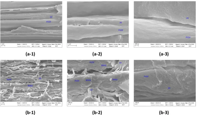
Fracture morphology for the binary blending film and the composite film charged by BNNS has been characterized by SEM. The cross-section selected for the observation is parallel to the stretching direction as presented in Figure 1. SEM images of the fractures of three samples are presented in Figure 4. At first, as presented in Figure 4 (a), it can be found that PP and PVDF are with the different structure. In the interior of the film, along the stretching direction, PVDF is formed as the parallel fiber structure with twisted lamellae morphology, while PP is formed as the orientated texture structure with the nodular morphology. As discussed in the XRD part,
during the stretching procedure, the blending melt flows from 230 oC to room temperature,
which makes PVDF crystallizes at first. Some twisting lamellae, transverse to the growth direction, will start to multiply as presented in Figure 4 (a-3) where the surface of PVDF fiber is with visible folding traces. These twisted lamellae are so-called “row structure” 13 as mentioned in XRD part. The crystallization of PP occurs later due to the lower Tc. Because of stretching at room
temperature, the fast crystallization of PP does favor to form spherulites as presented in Figure 4 (a-3); instead, there are some crystals with nodular morphology appearing. The nodular morphology is for PP α phase which is detected by XRD as mentioned and such a crystalline morphology is reported to have high ductility and flexibility.29 As a result, the increase of flexibility from the PP α phase with nodular morphology favors PP to form a continuous texture structure interpenetrating in the PVDF fibers. As a kind of polymer with fluoride atoms, PVDF is hard to adhesive with other materials due to the high surface energy. Hence, PP crystallites adhere little surrounding the PVDF fiber. As presented in Figure 4 (a-2) and (a-3), the adhesion between PVDF fiber and PP layer is not robust enough and the vacancy exists in the interfacial area.
If adding BNNS in the binary blending, as presented in Figure 4 (b-1), it can be found that the crystalline morphology of two polymers does not change but the surface of PVDF fiber is attached with BNNS because of mixing by DMF solvent at first. Thus, the attached BNNS serve as the nucleating agent for PP and promotes the crystallization of PP on the surface of PVDF as we have discussed in the XRD part. As presented in Figure 4 (b-3), some PP regions are found to adhere on the surface of PVDF fiber. In addition, in the composite film charged by BNNS, it is hard to find obvious agglomeration of BNNS in Figure 4 (b). Hence, by the characterization of fracture morphology of the binary blending film and the composite film, it can be found that the compatibility between PP and PVDF can be further enhanced by using BNNS.
(a-1) (a-2) (a-3)
(b-1) (b-2) (b-3)
Figure 4 Morphology of fracture surface for the two samples: (a) PP/PVDF (50-50) and (b)
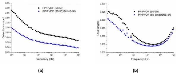
Frequency dependence of dielectric properties of the binary blending film and the composite film have been characterized in a wide frequency range from 0.1 Hz to 105 Hz at room temperature.
At first, the dielectric properties of PP are with the constant (ε) of 2.2 and loss (loss tangent tan θ) of 0.32% at 1000 Hz. By contrast, ε of PVDF is of 9.3 and its tan θ of 2.2 % at 1000 Hz. For the binary blending film, as indicated in Figure 5, it can be found that because of the high ε of PVDF, the binary blending film is also with a reasonable ε of 3.6 at 1000 Hz and meanwhile, tan θ of the binary blends is as low as 0.54%. If dividing the whole frequency range into two parts: low frequency region (lower than 100 Hz) and high frequency region (higher than 1000 Hz), it can be found that ε and tan θ of the binary blending film at low frequency are much higher than those at high frequency. It infers a strong interfacial polarization occurring in the binary blends. As inferred by XRD and SEM, the binary blending film consists of semi-crystalline structures with different crystalline morphology which creates much interfacial area between PVDF fiber and PP layer. When the sample is put in an AC electric field, the charges will be easy to accumulate at the interfacial area and arouse strong interfacial polarization. Interfacial polarization needs longer duration to release which makes the dielectric loss become high at low frequency.1 That is the reason that ε and tan θ of the binary blending film at low frequency range are both higher than those at high frequency.
For the composite films charged by BNNS, it can be found that comparing the binary blending film, adding BNNS will simultaneously reduce ε and tan θ. In the part of ε, as an isolating filler with ε of less than 4, the decreased ε of the composite films can be understand by the basic mixing law.30 In the part of tan θ, BNNS can help to reduce tan θ of the composite film at the whole measured frequency range. The composite film with BNNS has even lower tan θ at low frequency which infers weaker interfacial polarization occurring in the composite. The reduced tan θ of composites with BNNS also infers that using BNNS can modifier the interfacial adhesion between PP and PVDF and achieving better compatibility, which is corresponding with the observation by SEM.
(a) (b)
Figure 5 Frequency dependence of dielectric properties for PP/PVDF (50-50) and PP/PVDF
(50-50)-BNNS 5% , resepectively: (a) for dielectric properties and (b) for loss tangent
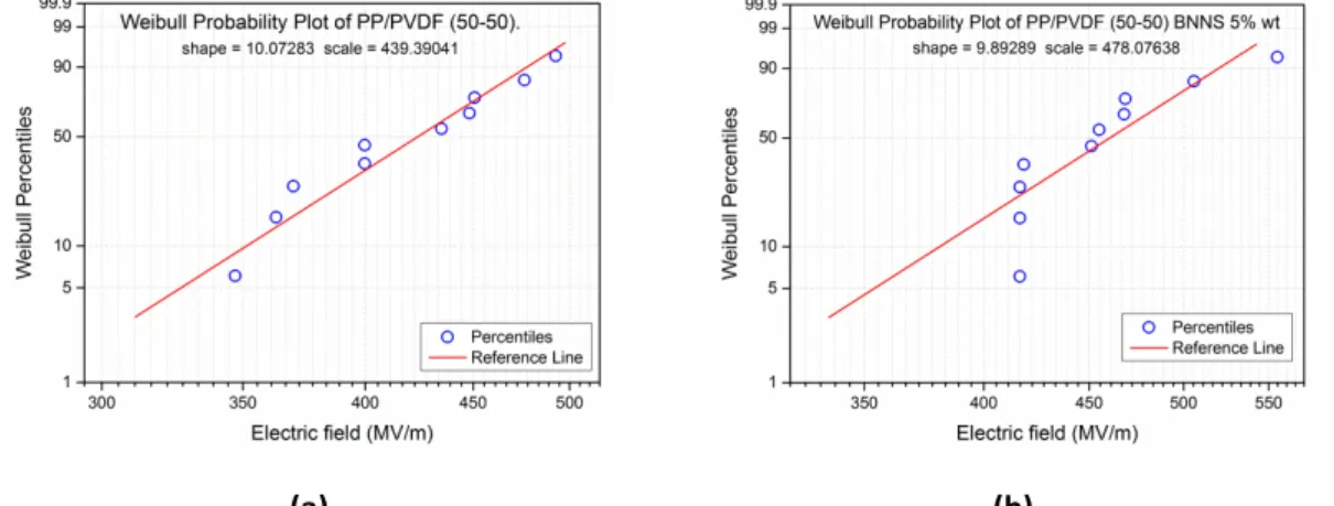
Dielectric breakdown strength (Eb) for two films have also been measured and the results are
analyzed by a two-parameter Weibull statistics as presented in Figure 6. It can be found that Eb of
solution casting.31 Such a high Eb of the binary blending film indicates that PVDF with low molecular weight can achieve compatibility with PP and the structure of the film is relatively compact. Meanwhile, there is no polar β phase found in this PVDF crystalline region which also assures high Eb.32, 33 For the composite film, it is found that using BNNS can further increase Eb of
the composite film which reaches 478 MV/m. As a kind of ceramics wit high thermal conductivity and high band gap, BNNS has been often reported to have a good reinforcement on composite’s Eb. Thus, in our study, it has also presented such an enhancement on the binary blending film.
Moreover, as presented in the SEM images, because of the long-term liquid exfoliation and mixing with PVDF in the DMF before blending, BNNS has little agglomerates in the composite which effectively avoids weak points for the growth of electric trees during the increasing of voltage.34 In addition, because of the influence on PP crystallization, the composite charged by BNNS can achieve better compatibility between PP and PVDF which also favors to improve Eb.
(a) (b)
Figure 6 Weibull distribution of Breakdown strength for PP/PVDF (50-50) (a) and PP/PVDF
(50-50)-BNNS 5% (b)
Besides the dielectric properties, the mechanical properties of two films have also been studied in this study. Young’s modulus and tensile strength of two directions, MD and TD in each film are presented in Figure 7. At first, it can be found that the mechanical properties of the binary blending film and the composite film are dependent on the stretching directions. The mechanical properties of MD are higher than those of TD. As discussed before, stretching at room temperature will cause PVDF crystallites to form fiber structures which cause the film with anisotropic mechanical properties.35 Furthermore, it can be found that adding BNNS can increase the Young’s modulus of two directions. Increased the Young’s modulus of the composite results from the high modulus of BNNS and more crystallinities of polymers. For the tensile strength, adding BNNS can also help to increase the tensile strength of two directions. Generally, for a material, the increased strength may result from a more compact structure. Hence, based on this point, it is understandable for the composite charged by BNNS has higher tensile strength in MD and TD due to its compact structure caused by the improved compatibility between PP and PVDF.
(a) (b)
Figure 7 Mechanical properties of PP/PVDF (50-50), PP/PVDF (50-50)-BN 5% and PP/PVDF
(50-50)-BNNS 5% films with two directions (MD and TD): (a) for the Young’s modulus and (b) for strength
Conclusions
Using PVDF with low molecular weight can achieve a good compatibility with PP because of the match in the flow induced crystallization behavior. Thus, the PP/PVDF of 50-50 weight ratio binary blending film with micro metric thickness can be fabricated by extrusion and stretching. The obtained binary blending film has reasonable ε over 3.6, low tan θ of 0.54% and high Eb of 439
MV/m. Furthermore, incorporated by BNNS of 5% weight fractions, the extrusion processed composite film has displayed further reduced tan θ of 0.41% and increased Eb of 478 MV/m. Such
improved dielectric properties result from the influence of BNNS on PP interfacial crystallization behavior on PVDF which benefits for more robust adhesion between two polymers. Because of the improved compatibility, the composite film containing with BNNS has also displayed higher Young’s modulus and tensile strength. Therefore, the enhanced dielectric and mechanical properties make PP/PVDF (50-50)/BNNS 5% display highly potential values for the application of film capacitors in HVDC systems.
Acknowledgements
This work is supported by the State Grid Corporation of China: The key technology research in dielectric films with large storage capacity for HVDC transmission (SGRDGKJ[2017]634) and within the MATMECA consortium and supported by the ANR under contract number ANR-10-EQPX-37. It has benefited from the facilities of the Laboratory MSSM at (CNRS UMR 8579), CentraleSupélec, France.
Reference
1 Huan T.; Boggs S.; Teyssedre G.; Laurent C.; Cakmak C. M.; Kumar S.; Ramprasad R. Advanced Polymeric Dielectrics for High Energy Density Applications. Prog. Mater. Sci. 2016, 83, 236–269.
2 Shen Y.; Lin Y.; Zhang Q. Polymer Nanocomposites with High Energy Storage Densities. MRS Bull. 2015, 40, 753-759
3 Chen Q.; Shen Y.; Zhang S.; Zhang Q. Polymer-Based Dielectrics with
High energy Storage Density. Annu. Rev. Mater. Res. 2015, 45, 433-458
4 Pourrahimi A.; Olsson R.; Hedenqvist M. The Role of Interfaces in Polyethylene/Metal-Oxide Nanocomposites for Ultrahigh-Voltage Insulating Materials. Adv. Mater. 2017, 1703624, 1-25.
5 Baer E.; Zhu L. 50th Anniversary Perspective: Dielectric Phenomena in Polymers and Multilayered Dielectric Films. Macromolecules 2017, 50, 2239–2256
6 Arun M.; Treich G.; Huan T.; Ma R.; Tefferi M.; Cao Y.; Sotzing G.; Ramprasad R. Rational Co-Design of Polymer Dielectrics for Energy Storage. Adv. Mate. 2016, 28, 6277–6291 7 Prateek V.; Raju K. Recent Progress on Ferroelectric Polymer-Based Nanocomposites for High
Energy Density Capacitors: Synthesis, Dielectric Properties, and Future Aspects. Chem. Rev.
2016, 116, 4260−4317
8 Dang Z.; Yan W.; Xu H. Novel High Dielectric Permittivity Poly(vinylidene fluoride)/Polypropylene Blend Composites: The Influence of the Poly(vinylidene fluoride) Concentration and Compatibilizer. J. Appl. Polym. Sci. 2007, 105, 3649–3655
9 Chen Z.; Pei J.; Li R. Study of the Preparation and Dielectric Property of PP/SMA/PVDF Blend. Mater. Appl. Sci. 2017, 7, 1-8
10 Cui K.; Liu D.; Ji Y.; Huang N.; Ma Z., Wang Z.; Lv F.; Yang H.; Li L. Nonequilibrium Nature of Flow-Induced Nucleation in Isotactic Polypropylene. Macromolecules 2015, 48, 694-699 11 Wu J.; Schultz J. M.; Yeh F.; Hsiao B. S.; Chu B. In-Situ Simultaneous Synchrotron Small- and
Wide-Angle X-ray Scattering Measurement of Poly(vinylidene fluoride) Fibers under Deformation. Macromolecules 2000, 33, 1765-1777
12 Lotz B.; Miyoshi T.; Cheng S. Z. D. 50th Anniversary Perspective: Polymer Crystalis and Crystallizations: Personal Journeys in a Challenging Research Field. Macromolecules 2017, 50, 5995-6025
13 Schrauwen B. A. G.; Breemen L. C. A. V.; Spoelstra A. B., Govaert L. E.; Peters G. W. M.; Meijer H. E. H. Structure, Deformation and Failure of Flow-Oriented Semicrystalline Polymers. Macromolecules 2004, 37, 8618-8633
14 Donnay M.; Tzavalas S.; Logakis E.; Boron Nitride Filled Epoxy with Improved Thermal Conductivity And Dielectric Breakdown Strength. Comp. Sci. Technol. 2015, 110, 152-158 15 Lu C.; Yuan L.; Guan Q.; Liang G.; Gu A. Optimizing Ply Pattern and Composition of Layered
Composites based on Cyanate Ester, Carbon Nanotube, and Boron Nitride: Toward Ultralow Dielectric Loss and High Energy Storage. J. Phys. Chem. C. 2018, 122, 5238–5247
16 Lee G.; Yu Y.; Lee C.; Dean C.; Shepard K. L.; Kim P.; Hone J. Electron Tunneling through Atomically Flat And Ultrathin Hexagonal Boron Nitride. Appl. Phys. Lett. 2011, 99, 243114 17 Li Q.; Zhang G.; Liu F.; Han K.; Gadinski M. R.; Xiong C.; Wang Q. Solution-Processed
Ferroelectric Terpolymer Nanocomposites with High Breakdown Strength and Energy Density Utilizing Boron Nitride Nanosheets. Energy Environ. Sci., 2015, 8, 922-931
18 Li Q.; Chen L.; Gadinski M.; Zhang S.; Zhang G.; Li H.; Haque A.; Chen L., Jackson T.; Wang Q. Flexible High-Temperature Dielectric Materials from Polymer Nanocomposites. Nature.
2015, 523, 576-580
Nanosheets Produced by Liquid Exfolization of Layered Materials, Science 2011, 331, 568 20 Chen J.; Huang X.; Zhu Y.; Jiang P. Cellulose Nanofiber Supported 3D Interconnected BN
Nanosheets for Epoxy Nanocomposites with Ultrahigh Thermal Management Capability. Adv. Funct. Mater. 2017, 1604754, 1-9
21 Dissado L. A.; Fothergill J. C.; Wolfe S. V.; Hill R. M. Weibull Statistics in Dielectric Breakdown; Theoretical Basis, Applications and Implications. IEEE Trans. Dielectr. Electr. Insul.
1984, EI-19, 227 - 233
22 Favaro M. M.; Branciforti M. C.; Bretas R. E. S.; A X-Ray Study of β-Phase And Molecular Orientation in Nucleated And Non-Nucleated Injection Molded Polypropylene Resins. Mat. Res. 2009, 12,1516-1439
23 Bohlen M.; Bolton K. Inducing the β-Phase of Poly(vinylidene fluoride) – A Review. Annu. Rev. Nanosci. Nanotechnol. 2015, 150110, 1-5
24 Mohammadi B.; Yousefi A. A.; Bellah S. M. Effect of Tensile Strain Rate And Elongation on Crystalline Structure And Piezoelectric Properties of PVDF Thin Films. Polym. Test. 2007, 26, 42-50
25 Fan B.; Bedoui F.; Weigand S.; Bai J. Conductive Network And β Polymorph Content Evolution Caused by Thermal Treatment in Carbon Nanotubes-BaTiO3 Hybrids Reinforced
Polyvinylidene Fluoride Composites. J. Phys. Chem. C. 2016, 120, 9511-9519
26 Offenbach I.; Gupta S.; Chung T. C. M.; Weiss R. A.; Cakmak M. Real-Time Infrared− Mechano-Optical Behavior And Structural Evolution of Polypropylene And Hydroxyl-Functionalized Polypropylene during Uniaxial Deformation. Macromolecules
2015, 48, 6294–6305
27 Laird E.; Li C. Structure And Morphology Control in Crystalline Polymer-Carbon Nanotube Nanocomposites. Macromolecules 2013, 46, 2877−2891.
28 Suplicz A.; Szabo F.; Kovacs J.G. Injection Molding of Ceramic Filled Polypropylene: The Effect of Thermal Conductivity And Cooling Rate on Crystallinity. Thermochim. Acta. 2013, 574, 145-150
29 De Rosa C.; Auriemma F.; Tarallo O.; Di Girolamo R.; Troisi E. M.; Esposito S.; Liguori D.; Piemontesi F.; Vitale G.; Morini G. Tailoring Properties of Polypropylene in the Polymerization Reactor Using Polymeric Nucleating Agents As Prepolymer on the Ziegle-Natta Catalyst Granule. Polym. Chem. 2017, 8, 655-660
30 Wang M.; Pan N. Predictions of Effective Physical Properties of Complex Multiphase Materials. Mater. Sci. Eng. R. 2008, 63, 1-30
31 Zhang Z.; Chung T. C. The Structure−Property Relationship of Poly(vinylidene difluoride)-Based Polymers with Energy Storage And Loss under Applied Electric Fields. Macromolecules 2007, 40, 9391-9397
32 Li W.; Meng Q.; Zheng Y.; Zhang Z.; Xia W.; Xu Z. Electric Energy Storage Properties of Poly(vinylidene fluoride). Appl. Phys. Lett. 2010, 96, 192905
33 Guan F.; Pan J.; Wang J.; Wang Q.; Zhu L. Crystal Orientation Effect on Electric Energy Storage in Poly(vinylidene fluoride-co-hexafluoropropylene) Copolymers. Macromolecules 2010, 43, 384-392
34 Shen Z.; Wang J.; Lin Y.; Nan C.; Chen L.; Shen Y. High-Throughput Phase-Field Design of High-Energy-Density Polymer Nanocomposites. Adv. Mater. 2018, 1704380, 1-6
Morphologies for Uniaxially Melt-Extruded High-Density Polyethylene Films Having An Initial Stacked Lamellar Texture. J. Mater. Sci. 1998, 33, 287-303