HAL Id: hal-00661089
https://hal.archives-ouvertes.fr/hal-00661089
Submitted on 18 Jan 2012
HAL is a multi-disciplinary open access
archive for the deposit and dissemination of
sci-entific research documents, whether they are
pub-lished or not. The documents may come from
teaching and research institutions in France or
abroad, or from public or private research centers.
L’archive ouverte pluridisciplinaire HAL, est
destinée au dépôt et à la diffusion de documents
scientifiques de niveau recherche, publiés ou non,
émanant des établissements d’enseignement et de
recherche français ou étrangers, des laboratoires
publics ou privés.
Interior layered deposits within a perched basin,
southern Coprates Chasma, Mars: Evidence for their
formation, alteration, and erosion
F. Fueten, Jessica Flahaut, L. Le Deit, R. Stesky, E. Hauber, K. Gwinner
To cite this version:
F. Fueten, Jessica Flahaut, L. Le Deit, R. Stesky, E. Hauber, et al..
Interior layered deposits
within a perched basin, southern Coprates Chasma, Mars: Evidence for their formation, alteration,
and erosion. Journal of Geophysical Research. Planets, Wiley-Blackwell, 2011, 116, pp.E02003.
�10.1029/2010JE003695�. �hal-00661089�
Interior layered deposits within a perched basin, southern
Coprates Chasma, Mars: Evidence for their formation,
alteration, and erosion
F. Fueten,
1J. Flahaut,
2L. Le Deit,
3R. Stesky,
4E. Hauber,
3and K. Gwinner
3Received 13 July 2010; revised 14 October 2010; accepted 30 November 2010; published 9 February 2011. [1]
A basin
‐like area containing three interior layer deposits (ILDs) on the southern
margin of Coprates Chasma was studied. We interpret the area as an ancestral basin and
demonstrate that ILD deposition postdates the formation of the current wall rock slopes.
The geometry of the ILD and the wall rock spurs form a catchment area between each
ILD and the plateau to the south. Erosional remnants of extensive ash or dust layers
deposited on the plateau south of Valles Marineris also crop out on the southern plateau of
Coprates Chasma. A mass balance calculation suggests that the volume of each ILD is
compatible with the volume of the ash or dust that would have been deposited within each
catchment area. We propose that the ILDs likely formed by episodically washing such
aerially deposited material down from chasma walls. Rifting of the Ius
‐Melas‐Coprates
graben opened the enclosed basin and removed any standing water. Faults within the
ILDs are compatible with this chasm opening. Sulfates are associated with the ILDs and
light
‐toned material on the basin floor. We suggest that they result from water alteration of
preexisting deposits, though the timing of that alteration may predate or postdate the
breaching of the basin. Scours within one ILD are similar to terrestrial glacial scours.
During a period of high obliquity ice would accumulate in this region; hence we argue the
scours are Martian glacial scours. A late deposited layer marks the end of the active
local geological history between 100 My and 1 Gy.
Citation: Fueten, F., J. Flahaut, L. Le Deit, R. Stesky, E. Hauber, and K. Gwinner (2011), Interior layered deposits within a perched basin, southern Coprates Chasma, Mars: Evidence for their formation, alteration, and erosion, J. Geophys. Res., 116, E02003, doi:10.1029/2010JE003695.
1.
Introduction
[2] Located on the flank of the Tharsis region, Valles Marineris is a 4000 km long linked system of troughs that has been the topic of numerous regional studies [e.g., Frey, 1979; Tanaka, 1986; Lucchitta et al., 1992; Mège and Masson, 1996; Mège, 2001; Mège and Ernst, 2001]. The formation of the chasmata of Valles Marineris is thought to have taken place during a two stage process [Lucchitta et al., 1994; Schultz, 1998]. Ancestral basins with irregular out-lines were proposed to form prior to the opening of the Valles Marineris [Lucchitta and Bertolini, 1990; Lucchitta et al., 1994]. Lucchitta et al. [1994] suggest that Hebes, south Ophir, south Candor and potentially south Melas
Chasma were sites of ancestral basins, while much of Coprates, north Melas and Ius may have formed during the later faulting episodes. Schultz [1998] proposed that the formation of ancestral basins culminated during the late Hesperian and that the rifting associated with the Ius‐Melas‐ Coprates graben occurred primarily during the Amazonian. [3] Located within these chasmata are numerous enigmatic layered deposits, referred to as interior layered deposits (ILDs) [Lucchitta et al., 1994], whose origin and mechanism of formation are uncertain. It has been suggested [Catling et al., 2006; Malin and Edgett, 2000] that ILDs are ancient deposits buried beneath the material which form the walls of troughs. However, most studies on ILDs suggest that they postdate the formation of the early basins; for example, Schultz [1998] and Head et al. [2001] suggest that they are Hesperian deposits. To date, there is no consensus on their origin. ILDs have been proposed to have formed in lacustrine [Nedell et al., 1987] or aeolian [Peterson, 1981] environ-ments; it has been also suggested that they are the result of pyroclastic volcanism in subaerial [Hynek et al., 2003; Chapman, 2002; Lucchitta, 1987, 1990] or subglacial [Nedell et al., 1987; Chapman and Tanaka, 2001; Komatsu et al., 2004] environments. More recently it has been proposed that they formed as spring deposits [Rossi et al., 2008].
1Department of Earth Sciences, Brock University, St. Catharines,
Ontario, Canada.
2
Laboratoire de Science de la Terre, UMR CNRS 5570, Ecole Normale Supérieure de Lyon, Université Lyon 1, Villeurbanne, France.
3
Institute of Planetary Research, German Aerospace Center, Berlin, Germany.
4
Pangaea Scientific, Brockville, Ontario, Canada. Copyright 2011 by the American Geophysical Union. 0148‐0227/11/2010JE003695
Furthermore, ILDs are thought to have been deposited syntectonically during basin collapse and individual mounds being remnants of filled subbasins [Fueten et al., 2008].
[4] Mineralogical data from both the OMEGA and CRISM instruments suggest the presence of sulfates within Valles Marineris [Mangold et al., 2007a, 2007b; Gendrin et al., 2005; Quantin et al., 2005; Bishop et al., 2009; Murchie et al., 2009a, 2009b; Flahaut et al., 2010a]. Sulfates have been associated with ILDs in most chasmata [Gendrin et al., 2005; Quantin et al., 2005; Le Deit et al., 2008; Flahaut et al., 2010b]. Chojnacki and Hynek [2008] argue that no single sulfate formation mechanism can account for the range of settings in which sulfates have been found. How-ever, it has been suggested that sulfates most likely formed in the presence of liquid water, under the acidic conditions of the Hesperian Epoch [Bibring et al., 2006; Flahaut et al., 2010a].
[5] Although Coprates Chasma was originally considered primarily a rift graben [Lucchitta et al., 1994], a recent study of an embayment in northern Coprates Chasma [Fueten et al., 2010] concludes that the area was an ancestral basin, in which ILDs were deposited. While Fueten et al. [2010] did not identify the mode of ILD deposition; they do sug-gest that transport mechanisms were incapable of distribut-ing the layered material evenly throughout the embayment. In this study we examine an area with a basin‐like geometry in the south of Coprates Chasma in which multiple ILDs are confined by wall rock spurs. The goal of this work is to understand the geological history of the area and to provide further information on the formation, deformation and ero-sion of ILDs.
2.
Geological Setting
[6] Coprates Chasma is one of the canyons of the Valles Marineris system, which is thought to have formed mainly by faulting during extension [Lucchitta et al., 1994]. The study area is located at the southern rim in the western part of Coprates Chasma (Figure 1). The southern boundary of the study area is formed by a plateau ridge with an elevation of approximately 3700 m (Figure 1b). This ridge has pre-viously been identified as the boundary between two major grabens within Coprates Chasma [Peulvast et al., 2001, Figure 10]: graben G6 to the south of the crest and graben G5 to the north. Both, Schultz [1991, Figure 10] and Peulvast et al. [2001] suggest the presence of major graben‐ forming, basin‐scale faults, immediately north and south of the ridge. Located approximately 25 km north of the plateau ridge is a lower ridge of wall rocks, which decreases in elevation from approximately−700 m in the west to −3200 m in the east (Figure 1). Only at the western end is this ridge connected to the southern plateau by a series of wall rock outcroppings. Wall rock geometry has thus created a basin‐ like structure (for brevity referred to as basin) with maxi-mum dimension of about 40 km by 25 km. The flat floor of this basin slopes from west to east, descending from an elevation of approximately −1300 m to −3000 m. At the eastern end, a gap in the northern wall rock ridge forms the geometry of an outlet to the basin into Coprates Chasma
proper, the floor of which has elevations of approximately −5500 m (Figure 1b).
3.
Geological Observations
3.1. Methodology for Attitude Measurements
[7] The primary data set for this study consists of a High Resolution Stereo Camera (HRSC) [Jaumann et al., 2007] panchromatic orthoimage, obtained during orbit 1995, with a resolution of 12.5 m per pixel and a corresponding digital elevation model (DEM) with a grid spacing of 50 m. Con-text Camera images with a resolution of 6 m per pixel (CTX) [Malin et al., 2007] (Figure 1) were registered to the HRSC image and hence its corresponding DEM. The atti-tudes of planar features were measured using the software Orion, following the methodology discussed in detail by Fueten et al. [2005], by fitting a plane to samples along exposed layering.
[8] Layering attitudes were measured on both the HRSC image as well as the CTX image mosaic. Where the same layer could clearly be identified in both images, measure-ments on different images were in good agreement. Due to the higher resolution of the CTX image more layers could be measured within the CTX composite and therefore, with one exception, data presented below is that from CTX images. Two High Resolution Imaging Science Experiment (HiRISE) [McEwen et al., 2007] images (PSP_001456_1695_RED; PSP_008194_1670_RED) were resampled to a resolution of 1m/pixel and registered to the DEM.
[9] The attitudes of remnants of faults were also mea-sured. Triangular facets that truncate wall rock spurs have previously been used to infer faults in the Valles Marineris region [e.g., Schultz, 1991; Peulvast et al., 2001, Figure 7; Wilkins and Schultz, 2003]. If the downfaulted spur is completely removed, the resulting geometry is that of a triangular facet that truncates wall rock; if the offset was less significant, the spur crest is displaced downward and the resulting facet is an inverted V shape.
[10] Inferring fault location from such a facet is clearly more subject to interpretation because the dip of the facet may subsequently have been modified by erosion. To reduce subjectivity and to determine the approximate strike of the faults, facets were measured by fitting a plane to them within Orion. We measured only facets for which both legs of the inverted V‐shaped spur were visible and that con-sisted of outcrop rather than debris. The spatial coordinates of points on the outcrop surface were measured and their positions adjusted until the best fit plane was deemed to be a good fit with the outcrop shape, with a maximum acceptable deviation of sampled points from the fitted plane of 30 m. Examples of such facets are shown in Figures 2b and 2c. 3.2. Wall Rock Faults
[11] A number of faults can be identified within the wall rocks (Figure 2a). The most prevalent set is approximately parallel to the trend of Coprates and has been suggested to be responsible for the formation of the grabens [Peulvast et al., 2001; Schultz, 1991]. Most faults dip to the north, with dip values from 30° to 45°; however these dip values may be the result of subsequent erosion. Hence only dip directions are shown in Figure 2a. Several faults bisect major wall spurs and the fault locations can be correlated with drops in
FUETEN ET AL.: LDS WITHIN COPRATES CHASMA, MARS E02003 E02003
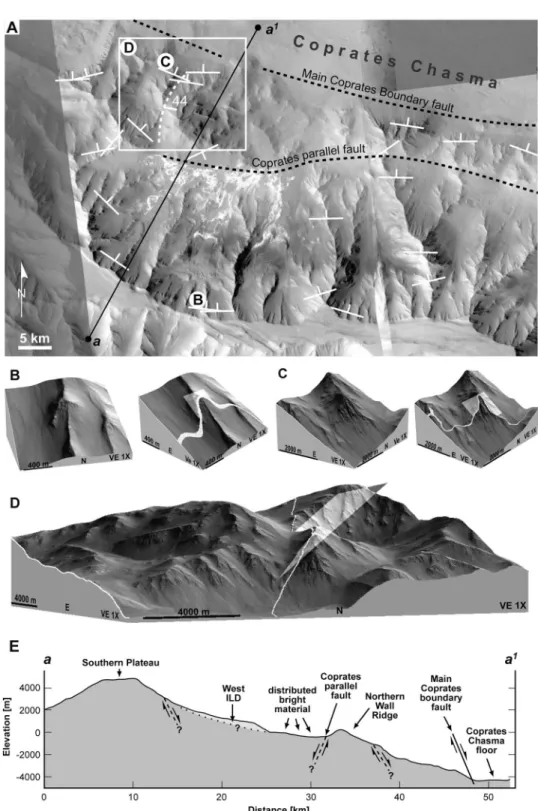
Figure 1. (a) Image of the study area, with the locations of the three ILD marked in yellow (1, western ILD; 2, central ILD; 3, eastern ILD; HRSC h1995_0000.nd). Inset on the upper right shows location of the study area in the wider context of Valles Marineris. (b) Hill‐shaded and color‐coded DEM of the same scene based on HRSC stereo images acquired during orbit 1995. (c) Detailed view of ILD and bright deposits in the basin center (mosaic of CTX images P04_002722_1673 and P18_008194_1669). (d) 3‐D perspective view of the basin‐like structure. Note that the floor of the basin slopes down toward a gap at the eastern end which is located to the left in this view (synthesized from HRSC stereo images of Mars Express orbit 1995).
Figure 2. (a) Measured fault segments are indicated with strike and dip symbols. The inferred locations of faults approximately parallel to Coprates north and south of the northern wall ridge are illustrated. The major cross fault attitude (011°/44°) is located on the western edge of the basin. Insets for Figures 2b, 2c, and 2d as indicated. (b) (left) Facet measured as fault; (right) measured plane dipping North and projected trace of plane. (c) (left) Facet measured as fault; (right) measured plane dipping North and projected trace of plane. (d) A 3‐D view of major cross fault, with projected plane and trace of plane as indicated. (e) Topographic cross section along line“a” to “a1.” The major Coprates boundary fault is shown as a solid line, other faults are schematically indicated as dashed lines. All faults are assumed to be normal faults. Also indicated is the western ILD, the location of the bright material within the basin, and the major topographic features.
FUETEN ET AL.: LDS WITHIN COPRATES CHASMA, MARS E02003 E02003
the elevation of the spur ridge on the order of 300–500 m (Figure 2b). We do not suggest that the faults identified in Figure 2a are the only ones in the area; they are merely the ones that can be identified using the criteria outlined above. [12] The southern boundary of the Coprates chasm floor is marked by a linear ridge of wall rock which rises 2 to 3 km above the chasm floor. The northern boundary of this ridge is marked by several fault segments that could be measured directly. This ridge is approximately 5 km wide to the east of the basin but widens to approximately 13 km at the western edge of the basin. The southern boundary of this ridge is most likely a Coprates‐parallel fault, which is well defined topographically and contains two spur truncations measurable that could be measured using our criteria. We suggest this fault most likely continues within the basin as illustrated in Figure 2a. Its southerly dip is suggested by the topographic expression.
[13] There is evidence for at least one large planar cross fault dipping 44° in the western end of the lower wall rock massif (Figure 2d). The attitude of this feature was obtained by fitting a plane to the fault trace over a distance of 6.7 km. Several curved sections of wall rock located near this cross fault may also have served as cross faults but could not be measured. A schematic cross section (Figure 2e) illustrates the relationship between the ILDs, the main Coprates faults and the northern wall ridge.
3.3. Interior Layered Deposits
[14] Much of the basin floor is covered by surficial dunes or by late deposits, which following the terminology of Malin and Edgett [2000] and Fueten et al. [2010] are referred to as thin mesa‐forming material. Outcropping in areas not covered by surficial material is light‐toned layered material (Figure 1). In the north central part of the basin where the light‐toned material is exposed well enough to be measured, its attitude is approximately 300°/12°. No obvi-ous signs of faulting were observed in the light‐toned material within the central portion of the basin. Along the southwestern spur extending from the southern wall light‐ toned material can be identified up to an elevation of approximately 0 m.
[15] Located near the southern wall are three prominent ILDs (Figure 1; here designated east, central, and west) which are discussed in more detail below. Each is loosely confined between two wall rock spurs; none extend signif-icantly beyond the extents of their confining spurs and the top elevation of all three deposits is within 150 m of each other. In each deposit, the northern erosional edge displays well defined layering. Their presumed contact with the southern wall rock is covered by surficial deposits or thin mesa‐forming material. Overall, layering in each deposit dips gently toward the north, although some exceptions will be discussed below. Spectral data, which will be discussed separately, suggest that the ILDs and the light‐toned mate-rial in the basin share similar mineral compositions. 3.3.1. East ILD
[16] The width of the ILD as defined by the spacing of the wall rock spurs is approximately 5 km. Its northern edge has a well developed erosional scarp beyond which light‐toned material considered to be part of the basin floor can be identified. A cover of thin mesa‐forming material obscures
its southern extent and the simplest assumption is that it thins out against the rising wall rock slope. The ILD consists of two lobes (Figure 3a), the highest elevation of the eastern one (∼−100 m) being approximately 3800 m below the local plateau level of∼3700 m. Total exposed thickness along the western and eastern lobes is∼700 m and ∼500 m, respec-tively. Layers at the lowest stratigraphic levels (small arrows Figure 3b) dip 12°–18° to the northwest. This approximates the local slope of the eastern bounding spur as it becomes visible beyond the ILD (Figure 3b, large arrows). Layers at higher stratigraphic levels are shallower with dips of 7°–12° while the dip direction rotates from the NE toward a more northerly attitude. While some of the layers at the upper stratigraphic levels can be traced across both lobes, there is also evidence that layers from the thicker western lobe thin out and merge on the eastern lobe (Figure 3c).
[17] Layer thickness, as estimated by registering the HiRISE image (PSP_002722‐1665_RED), resampled to 1 m/pixel, to the HRSC DTM, is in the range of 5 m to 15 m. However, some layers thin out completely. Layering exhibits polygons (Figure 3d) which are produced by two approxi-mately perpendicular sets of parting planes. The strike of one of these sets appears to be parallel to the trend of Coprates Chasma, while the dip of the planes is nearly vertical. The parting planes are not as straight and regular as those described near Ceti Mensa [Birnie et al., 2010]; the polygons outlined by these parting planes are on the order of 5m in diameter. Viewed at full HiRISE image resolution, there are no obvious inclusions of wall rock boulders within the layering, and the size and appearance of fragments in front to the erosional scarp is consistent with material derived by the erosion of polygons.
[18] While the ILD has not been extensively deformed, several minor faults and closely spaced fractures (Figure 3e) trending 120°–125° are visible on both sides of the eastern lobe. Also present within this ILD are two smooth hollows. Identification of the larger central one is primarily based on the change in erosional characteristics. Of particular interest are the two on the western side of the deposit (Figure 3a). Their width exceeds 130 m, while their depth is estimated to be less than 10 m. These two grooves are not parallel to the local slope.
3.3.2. Central ILD
[19] The main body of this ILD is very similar to the east ILD (Figure 4a). Its width between spurs is approximately 3 km, its length from erosional edge to its presumed southern termination approximately 4.5 km. Layers dip approximately 14° toward the north and appear to curve, with a low in the center between the ridges and higher elevations near the wall rock ridges (Figure 4b). The total thickness of the ILD is estimated to be approximately 300 m, while layer thickness is on the 5 m–15 m scale. Polygons are visible on the west side of the ILD within HiRISE image PSP_007403_1670_RED (Figure 4c). These polygons are of the same scale as those observed in the east ILD and also appear to be produced by two nearly perpendicular parting planes, one of which is approximately parallel to the trend of Coprates. A second outcropping of ILD is located near the wall rock spur to the east. On the east side of the ILD minor faults trend 115° (Figure 4d), while at least one more significant fault is observed within the CTX image (P06_003355_1673_XI_ 12S064W) trending∼100° (Figure 4e).
3.3.3. West ILD
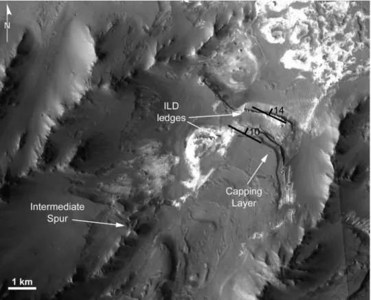
[20] Observations of this ILD are limited to HRSC and CTX imagery, as no HiRISE data are available. The ILD is confined between two wall rock spurs, with a higher lobe to the west (Figure 5). This higher lobe can be traced back to an intermediate spur further to the south. The northern edge of the ILD is primarily defined by two ledges. The northern ledge appears to decrease in elevation from approximately 250 m at the western end to approximately 100 m at the east. At this location the ILD is approximately 4.2 km wide. The smaller southern ledge is approximately 150 m high. The total thickness of the ILD is estimated to be approximately 600 m. We interpret that the southern ledge is capped by
thin mesa‐forming material which is between 30 m to 90 m thick. Because of the lack of visible intermediate layers along the ledges, layering measurements in this unit are based on the attitudes near the front of the erosional ledges. These dip gently toward the north.
3.3.4. Thin Mesa‐Forming Unit
[21] Much of the area and in particular the wall rocks are covered by a dark capping layer. Such dark‐ to intermedi-ate‐toned capping units were described by Malin and Edgett [2000] as“thin mesa” units, hence we refer to this unit as a thin mesa‐forming unit. In the area of the central ILD, this unit is unconformable to the layered material (Figure 6a) and in this area can be estimated to be 30–60 m thick. This Figure 3. (a) East ILD with layer attitudes and elevation contours. The two major linear grooves are
located immediately north of the location of inset of Figure 3e. (b) A 3‐D view of the deposit. Small arrows indicate how basal layering follows the slope of the local wall rock. (c) Detail of layer merging. (d) Polygons visible near the tip of the erosional edge. (e) Fractures on the west side of the deposit.
FUETEN ET AL.: LDS WITHIN COPRATES CHASMA, MARS E02003 E02003
unit also displays some linear erosional features (Figure 6b) directed approximately downslope. The fault observed in the layered material within the central ILD cannot be traced through the capping dark unit and no deformation features are observed within the thin mesa‐forming unit. Hence, this fault was active before the deposition of the thin mesa‐ forming unit.
4.
Mineralogy
4.1. Method
[22] Compact Reconnaissance Imaging Spectrometer for Mars (CRISM) spectral imager (MRO, NASA, 2005)
acquires images in a high‐resolution targeting mode and a lower‐resolution mapping mode using two detectors, in the VNIR and IR domains [Murchie et al., 2007, 2009a]. CRISM provides images at 544 different wavelengths (at 6.55mm/channel) between 0.362 and 3.92 mm in hyper-spectral mode, while surveys in multihyper-spectral mode yield images at 72 wavelengths, selected to cover absorption fea-tures of mineral groups of interest. Spatial resolutions range from 18 to 40 m per pixel for hyperspectral data to 100 to 200 m per pixel for multispectral ones.
[23] Two CRISM hyperspectral observations (FRT0000A16E and FRT0000A993), acquired at the same location at 18 m per pixel, are available on the studied area. The data set is Figure 4. (a) Central ILD with layer attitudes. (b) A 3‐D view with 2X vertical exaggeration to illustrate
layer curvature conforming to the approximate wall geometry. (c) Polygons produced by nearly perpen-dicular parting planes. (d) Minor faults in a HiRISE image PSP_008194_1670_RED in the western por-tion of the ILD. (e) Fault visible within CTX image CTX P04_002722_1673_XI_12S064W.
supplemented with the MSW000055D3 multispectral observation, having a spatial resolution of 100 m per pixel.
[24] CRISM data are processed using steps developed by the CRISM team and available through use of the publicly released CAT (CRISM Analysis Tool). In the present study, only data from the L detector, corresponding to the IR domain, were used. The 1 to 2.6 mm interval is where spectral features of hydrated minerals are. Both hyperspec-tral and multispechyperspec-tral data were processed using the method
described by Flahaut et al. [2010a]. The final products are mineralogical maps derived from atmospheric‐corrected CRISM data [McGuire et al., 2008] that we then projected over HiRISE and CTX data in a GIS system.
4.2. Results
4.2.1. Identification of Signatures
[25] Hydrated minerals are identified in hyperspectral observations by investigating the overtones and
combina-Figure 6. (a) Angular unconformity between thin mesa material and the ILD within HiRISE image. (b) Linear erosional features within CTX image (P07_003711_1680_XN_12S064W).
Figure 5. CTX image (P07_003711_1680_XN_12S064W) of ILD. Features discussed in text are labeled.
FUETEN ET AL.: LDS WITHIN COPRATES CHASMA, MARS E02003 E02003
tions of fundamental vibrational absorption features in the spectrum. As a residual atmospheric contribution often persists in CRISM data, especially around 2 mm, spectra of interest were ratioed by spectra of homogeneous dusty regions extracted from the same CRISM cube. This reduces the noise inherent to the data and enhances the spectral features around the 2 mm wavelength. Some well‐known minor instrumental artifacts are still present after processing, such as the 1.65mm feature, which is linked to the detector boundary [Murchie et al., 2007]. Two different spectral types have been identified in the present area. The most common spectral type shows a diagnostic absorption band at 1.94mm, coupled with a weaker one at 1.43mm, and a drop at 2.4 mm. The 1.9 mm absorption band is present in all the hydrated minerals. The 1.4mm band, sometimes present, results from both H2O and structural OH bending and stretching
vibra-tions. By contrast, the 2.4 mm band characterizes the SO4
groups and is diagnostic of sulfates. The combination of these three absorption features characterizes polyhydrated sulfates [Gendrin et al., 2005; Flahaut et al., 2010a].
[26] The second spectral type we observed has spectral features at 2.13 and 2.4 mm, revealing the presence of monohydrated sulfates. It is especially the shift of the bound
water vibration from 1.9 to 2.1mm that is characterizing the presence of a single water molecule in the sulfate structure. The shapes of the spectra are consistent with Mg or Fe monohydrated sulfates. Nevertheless, the precise position of the band at 2.13mm with a weak doublet is probably more indicative of kieserite (MgSO4) rather than szomolnokite
(FeSO4).
4.2.2. Distribution of Sulfates
[27] The distribution of both polyhydrated and mono-hydrated sulfates was determined using summary parameters of Pelkey et al. [2007] on hyperspectral and multispectral data.
[28] The identified CRISM signatures, superimposed on CRISM RGB and HiRISE images are illustrated in Figure 7. Results show a complete spatial correlation between the sulfates signature and the light‐toned deposits of the ILD mound and surroundings. The cliffs of the central and the west ILD mound are composed of polyhydrated sulfates, with spectra characterized by 1.9 and 2.4 mm diagnostic absorption bands. Patches of light‐toned deposits located around the main ILD mound, especially at the bottom of the cliffs, are also enriched with polyhydrated sulfate signatures. The spectral signatures characteristic of sulfates are less Figure 7. (a) Map of sulfate detections realized with CRISM. Green areas are enriched in polyhydrated
sulfates; red areas are enriched in monohydrated sulfates. Background is a combination of CRISM obser-vations in false color, HiRISE, and THEMIS visible data. (b) Comparison of CRISM FRT0000A16E ratioed spectra (pointed to by arrows) to sulfate spectra from the USGS spectral library (continuous lines). Green, polyhydrated sulfates; red, monohydrated sulfates. The 1.65mm feature, which is an instrumental artifact, has been removed for clarity. Dashed lines have been added at 1.43, 1.93, 2.13, and 2.4mm to aid with the interpretation of the spectra.
strong in the eastern part of the central ILD, which may be covered by a significant amount of dust.
[29] Monohydrated sulfates (2.1 and 2.4 mm diagnostic absorption bands) are found very locally in a topographic low, and on a dusty scarp, located on the edge of the CRISM observation. The monohydrated sulfates detected cover a 600 m by 200 m wide light‐toned stratified mound. This mound does not seem morphologically different from the polyhydrated sulfates outcrops, except that it is spatially isolated.
[30] The thin mesa‐forming unit covering the ILD does not have any spectral signature diagnostic of any charac-teristic minerals. This can reasonably be explained in two ways: (1) the accumulation of dust on this flat area could mask any relevant signature, giving it a flat spectral appearance or (2) the thin mesa unit is made up of a neutral material, which does not have any significant absorption features in the CRISM L detector wavelength range.
5.
Discussion
5.1. Basin‐Like or Basin?
[31] In their present configuration the three ILDs are perched between 200 m and−1400 m above the local basin floor. However, the elevation of their top is within∼150 m of each other, which suggests that their formation was not completely independent. The easiest way to link all three deposits is by assuming that they formed within a single basin with a common water level. Models of ILD formation include basin filling mechanisms [Lucchitta and Bertolini, 1990; Lucchitta et al., 1994; Nedell et al., 1987; Fueten et al., 2010].
[32] In its present geometry, with the outlet region connected to Coprates Chasma, the basin could only contain a standing pool of water if Coprates was also filled with water. With the depth of Coprates in this area at approxi-mately at −5500 m and the highest elevation of the basin floor at approximately −1000 m or light toned material at 0 m, the water depth would have had to be considerable. However, if the northern wall rock ridge had at one time been more elevated than its current position, the basin could have contained water independently of Coprates Chasma. 5.2. Faulting
[33] A number of scarps interpreted as faults were located within the study area. In addition to the main Coprates boundary fault, there is evidence for a major Coprates‐ parallel fault to the south of the northern wall rock ridge. If the Coprates‐parallel fault is interpreted as south dipping, the most likely interpretation of the northern wall rock ridge between the two major faults is that it is a horst. The interior of that basin would then be a graben. At least one major cross fault is located at the western edge of that wall rock ridge. Wilkins and Schultz [2003] suggest that basin‐truncating cross faults are produced by reactivation of preexisting wrinkle ridges. The importance of that cross fault and other possible cross faults is that it decouples the northern wall rock ridge from the plateau to the south, allowing for independent movement of that block.
[34] Interpreting the northern wall rock ridge as a horst would thus imply that either side had to drop lower than the horst which itself dropped in elevation. The evidence of
several major faults presented above suggests major wall rock rearrangement within this area was possible.
[35] However, the time of their movement cannot be con-strained. To create a basin capable of holding water inde-pendent of Coprates Chasma, we suggest two possibilities:
[36] 1. Basin formation during Valles Marineris opening. The basin would be created during the Amazonian at the time of the formation of the Ius‐Melas‐Coprates graben [Schultz, 1998]. The two major Coprates‐parallel faults are consistent with displacement during Valles Marineris opening. Their action would have lowered both the floor of Coprates and the northern wall rock ridge within the area. Collapse of the interior of the present basin would have created the basin, leaving the northern wall rock ridge as a horst. In this scenario there needs to be a hiatus in the deformation to enable the basin to hold water prior to achieving its present orientation.
[37] 2. Basin formation prior to Valles Marineris opening. In this scenario the current basin formed as an ancestral collapse basin during the Hesperian [Schultz, 1998] that was subsequently segmented by the Coprates faulting. In this case the Coprates parallel fault likely formed along the northern boundary of the ancestral basin.
[38] The fracturing and minor faulting documented within the ILDs is nearly parallel to the major faults within Coprates and is compatible with both basin forming models. The lack of offset of layering within the ILD mounds indicates that displacement here was minor. There is no visual evidence for the southern Coprates‐parallel faults within the central portion of the basin. This suggests that later deposition covered the fault trace.
5.3. Formation of ILDs
[39] Each of the ILDs described is laterally constrained by two wall rock spurs and no ILD is elevated above its adjacent wall rock spurs. The basal layers of the east ILD appear to conform to local spur slope and the overall geometry of the ILDs suggests that it fills a preexisting topographic low between two spurs. Hence the formation of the ILDs post-dates the formation of the current wall rock geometries. ILDs are thus not exhumed deposits. These arguments also suggest that the region enclosed by the wall rock spurs is of impor-tance for the formation of each ILD. If ILDs were deposited between preexisting wall spurs, then the material removed for the formation of the spurs cannot serve as ILD material. No large boulders are visible within the ILD, which might be expected if they were at least partially composed of locally redeposited wall rock slumps. In fact the lack of basement boulders within the ILDs suggests that the erosion of the wall rock was nearly complete and that wall rock geometry was in its current form prior to ILD deposition. Isolated boulders of wall rock may be contained within the ILD but are not present within the visible sections. The internal structure of the deposits appears to consist of conformable layers that gently dip downslope. The simplest hypothesis for the origin of these ILDs is that they formed by the episodic deposition of material in layers. While both, aeolian and lacustrine environments are possible, we argued above that this region was a basin. The approximately constant maximum elevation of light‐toned material within the ILDs and the wall rock suggests that the basin was filled with water at some time. The extensive distribution of light toned material favors an
FUETEN ET AL.: LDS WITHIN COPRATES CHASMA, MARS E02003 E02003
aerially distributed source material for the ILD, such as ash or dust.
[40] An extensive light‐toned formation, up to 100 m thick, covers parts of the plateaus around Valles Marineris [Weitz et al., 2010; Le Deit et al., 2010a]. They are most likely air fall material such as volcanic ash or dust in origin [Le Deit et al., 2010a], suggesting that a regionally exten-sive source of fine‐grained material was available. Thin light‐toned exposures are observed on the plateau to the south of the ILD mounds (Figure 8). These light‐toned exposures may correspond to altered basement [Le Deit et al., 2010b]. Another possibility is that they are rem-nants of the thickest outcrops of the extensive light‐toned formation. Regionally extensive airborne material would most likely have also been deposited within the basin and on the walls.
[41] In a wet environment, material aerially deposited on the walls could be expected to be washed down the slope and deposited within the basin at the location of the large ILD deposits. In such a situation, bounding wall rock spurs would constrain the geometry of a catchment area that feed each ILD. To test this hypothesis, we performed a simple mass balance calculation.
5.3.1. ILD Mass Balance Calculation
[42] This hypothesis addresses several questions that can provide insights into the origin of these ILDs. These ques-tions are: What overall thickness of aerially deposited material is required in each catchment area to produce the observed ILD? Is that required thickness approximately the same for each ILD? Is that thickness compatible with the thickness of layered material observed on the plateau? [43] This type of calculation clearly depends on a number of assumptions. Determining the catchment area for an ILD is relatively simple for areas 1 and 2 (Figure 9a), as they are bordered by the top of the plateau to the south and wall spurs on either side (Figure 9). The definition of the catchment area 3 is more difficult as material deposited on the walls of the western bounding spur (Figure 9b, hatched area) may well bypass the thicker main portion of the mound if transported. For simplicity, this area has been included in the calculation. Determining the volume of each ILD is also subject to interpretation. Their shapes were approximated to those of rectangular wedges. The sectional area of each wedge was calculated by estimating the slope at the top and the base using elevation at the points indicated (Figure 9a). The main
assumptions are that the ILD thins to 0 m thickness to the south and that elevations A and C are near the base of the ILD and that the original length did not exceed significantly those indicated. While the original extent of the ILDs is not known, this assumption may be reasonable because the original basin would have been narrower than its current extent. Two separate estimates for the length of the ILDs were used. The shorter estimate (Figure 9a, length C1) is based on the extent of the main mound, while the longer estimate (Figure 9a, length C2) extends to the northern limit of thick ILD that can be directly traced to the main mound. [44] The calculated thickness of a regionally extensive ash unit required to be deposited in the catchment areas (Figure 9a, colored regions) to produce the ILD ranges from 27 m to 71 m for the shorter ILD (Figure 9) to 68 m to 125 m for the longer ILD units. As expected, the required thicknesses based on shorter ILD length are less than those for longer ILDs. The calculated deposition thickness for area 3 is the lowest. Removing the hatched portion from the catchment area 3 would increase the amount of ash required to be deposited in each area. For each model of ILD length, the thickness for each catchment area varies by less than a factor of 3. We consider the calculations to be in good agreement of each other. This mass balance indicates that it would require a total thickness on the order of∼100 m or less of material distributed over the catchment area to pro-duce the assumed volume of ILD. This thickness may be derived by numerous thinner aerial deposition events which are then individually washed down into the basin. This total thickness is comparable to the thickness of layered material deposited on the plateau [Weitz et al., 2010; Le Deit et al., 2010a].
5.3.2. Role of Water
[45] While this mass balance calculation does not prove any theory of formation of the ILDs, it does illustrate that their volume is compatible with the redeposition of material aerially deposited within their catchment area. Since we accept the presence of water within the basin, we suggest that this material was washed down periodically and deposited in the shallow portion of a lacustrine environment. The very presence of layering suggested an episodic nature to the redeposition. It should be pointed out that the basic mechanism proposed here, namely the periodic washing down of accumulated material would work under several climatic models. For example, seasonal meltwater could serve the same purpose as episodic rain. However, in the absence of direct evidence for any particular climate, we simply assume that water was available to wash accumu-lated material into the basin. It is not known if water was continuously present within the basin. The lack of any delta fans could argue against the presence of perennial water filling the basin. However, the northern edges of all ILDs are clearly truncated by erosion, leaving no evidence for the presence or absence of deltaic features.
[46] Within HiRISE images, polygons are visible on both the eastern and central ILDs. Similar polygons have been described within light‐toned layering in HiRISE images by Weitz et al. [2008] and Pondrelli et al. [2008]. Pondrelli et al. [2008] suggests the light‐toned beds were disrupted into polygons through tectonic stress or thermal contraction and later deformed. Weitz et al. [2008] proposes thermal contraction or desiccation of hydrated minerals as a possible Figure 8. Light‐toned exposures on the plateau to the
southeast of the east ILD mound (CTX image P08_ 004067_1681_XN_11S_064W).
formation mechanism. Thermal contraction could be due to an ice‐rich cover of the ILDs. If the polygonal structures are the results of desiccation of hydrated minerals [Weitz et al., 2008], water levels may have dropped periodically below ILD levels and led to their desiccation as it is proposed for other Martian lakes [El Maarry et al., 2010].
5.4. Erosion of ILDs
[47] All ILDs show clear evidence of erosion at their northern limits. However, of particular interest are two approximately 100 m wide and less than 10m deep hollows observed within the east ILD. These troughs are smooth with well‐defined edges, devoid of localized slumping.
Unlike other erosional features along the erosional edge of the ILD they are not parallel to the local slope (Figure 10a). There is no evidence that these hollows are of structural origin.
[48] These hollows must have been carved after the ILD had been solidified. The troughs do not have the appearance of yardangs or other aeolian features, and are more likely to have formed by water, ice or a combination of the two. In its present geometry most water would flow along the 250 m deep channel between the wall rock spur and the western edge of the mound. A continuous flow would also carve channels parallel to the local slope, which these are not. The size of the catchment area is well constrained and relatively Figure 9. (a) Spur‐bounded catchment areas for the three ILDs. Spur‐bounded area 4 was not used for
any calculation as it would not contribute to either east or central ILD. Scale bars indicate the dimensions used for estimates in the table. (b) A 3‐D view of the catchment areas.
FUETEN ET AL.: LDS WITHIN COPRATES CHASMA, MARS E02003 E02003
small; it would require a significant precipitation event to produce such a volume of water. While arguing for a glacial origin of larger‐scale Martian outflow channels, Lucchitta [1982] pointed out that troughs sculpted by ice would require far less discharge volume than those carved by water.
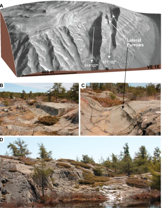
[49] We suggest that these hollows are very similar to well‐known U‐shaped glacial scours observed on Earth. Figures 10b–10d depicts documented glacial scours from Whitefish Falls, Ontario, Canada [Hambrey, 1994, Figure 3.10a]. Here, the scours feature the same shallow channel, with smooth, straight edges, observed in the east ILD. Lateral furrows [Shaw, 1994, Figure 3] present in the
terrestrial example (Figure 10c) are very similar to two fea-tures observed with the western most trough in the ILD (Figure 10a). While most of the scours on Earth are narrower than those observed within the ILD, several reach the same approximate dimensions (Figure 10d). In addition to the visual similarities, a glacial origin for these scours within the ILD overcomes two problems that a purely fluvial origin has. In a fluvial setting there would be a one‐to‐one relationship between precipitation and flood events, as the small catch-ment area would drain very quickly. In a cold glacial setting, the precipitation could accumulate to form the glacier responsible for the scouring. Second, the scouring beneath an ice sheet is less constrained by local underlying topography. Figure 10. (a) Broad hollow not parallel to local topography. (b) Broad hollow with gently sloping
curved wall. (c) Channel division similar to those observed in the ILD. Same location as Hambrey [1994, Figure 3.10a] and Shaw [1994, Figure 3]. (d) Larger channel. Small bushes in all Earth images approximately 0.5–1 m high. Photos by F. Fueten.
Hence the troughs would not have to be parallel to the local slope.
[50] There is considerable evidence that glaciation and ice‐related processes were important during periods of high obliquity in middle‐ to high‐latitude Martian regions [e.g., Head et al., 2003]. Indeed, ice is currently present in mid-latitudes [Holt et al., 2008; Byrne et al., 2009], and was likely present in the past, too [Hauber et al., 2008]. Recent observations indicate that water ice is currently present even at low latitudes [Vincendon et al., 2010a, 2010b]. Evidence for possible glaciers inside the Valles Marineris has previ-ously been discussed by, for example, Whalley and Azizi [2003], Chapman et al. [2005], and Mège and Bourgeois [2010]. Modeling by Madeleine et al. [2009] suggests that ice accumulation rates of ∼10 mm/yr lead to the formation of a 500–1000 m thick regional ice sheets during the Amazonian. Hence we suggest these troughs are glacial scours that were produced during a period of glaciation, possibly during the late Amazonian.
5.5. Formation of Sulfates
[51] Spectral data show that the ILD in the study area contain sulfates. Other components, such as dehydrated salts, which do not have any spectral features, may be present but cannot be detected from orbit.
[52] Our findings are consistent with previous studies of the Valles Marineris area [Gendrin et al., 2005; Quantin et al., 2005; Bishop et al., 2009; Murchie et al., 2009b; Flahaut et al., 2010a]. Sulfate detections have been spa-tially correlated with the large ILDs commonly found in the center of most of the chasmata [Gendrin et al., 2005; Quantin et al., 2005; Flahaut et al., 2010b]. They are likely to have been formed in the presence of liquid water, under the acidic conditions during the Hesperian Epoch [Bibring et al., 2006; Flahaut et al., 2010a, 2010b]. Their formation mechanisms, which may vary from one chasma to another, are still debated.
[53] Sulfates on Earth are commonly found as evaporites in deep and shallow basins [e.g., Warren, 2010] or as alteration products in volcanic or hydrothermal environ-ments [Flahaut et al., 2010a, and references therein]. The previous morphological observations and the small size of the study area allow us to favor or rule out some of these formation mechanisms.
[54] Sulfates on Mars require water to form [Murchie et al., 2009b]. We would expect the sulfates in Coprates to have been formed at the contact with some liquid water in the basin, whether it was a lake or due to groundwater flow with no free standing surface waters. Since formation of sulfates cannot occur under current Martian conditions [Roach et al., 2009] and the ILDs have been eroded, the sulfates must form the bulk of the ILD rather than being a superficial alteration crust. The exposed sulfates therefore constitute the bedrock of the ILD.
[55] Sulfates can be formed primarily by precipitation in a shallow basin. If we assume the basin was closed at some time, this mechanism could account for the sulfate‐rich bright deposits found on the basin floor. However, the perching and tilting of the ILDs is hard to explain in such a deposition medium. If we consider ash or dust deposited on the surrounding plateaus and walls as the source for sulfur, this material would have to be dissolved by water before the
precipitation of sulfates on the same walls. The geometry of the ILDs and the apparent lack of thick deposits at the bottom of the basin make direct precipitation of sulfates unlikely.
[56] If water transport is responsible for the formation of the ILDs, a supply of groundwater at ILD locations would most likely be present. Not all rainwater or melting snow cover would wash down the walls immediately, as the faulted basaltic wall rock can be expected to be highly fractured and permeable. Groundwater within those frac-tures could have a significant hydraulic head if an interconnected network of fractures existed at least part of the distance up the wall slopes. This water may thus saturate the ILDs episodically. If sulfates are not formed as a primary mineral, they could be produced by the chemical weathering of aeolian ashfall by a temporary supply of stagnant water [Mangold et al., 2010]. If the primary material originates from a volcanic event, it is very likely that sulfur from the volcanism was present in the ashes or in the environment at this time. The alteration of ash deposits into sulfates could have lead to the cementation of the deposits at their current location. This formation mechanism could well explain the current shape and position of the deposits and would explain why no light toned material is observed above an elevation of 0 m.
[57] An alternative model suggests that sulfates may form by weathering of the ILD material by ice. Niles and Michalski [2009a] argue that sulfate rich deposits in Mer-idiani Planum and Mawrth Vallis [Niles and Michalski, 2009b] form by acid weathering inside massive ice depos-its. However, according to this mechanism the deposits are sublimation leftovers of large ice fields, while we suggest that ILD material was washed down the slopes by water. It may of course be possible to allow for ice alteration mech-anism incrementally as the ILD thickness builds up. How-ever, this requires a fairly complex climate involving periodic melting to wash the material into position, alter-nating with periods of ice to allow for the weathering for which we have no direct evidence. Hence we do not favor this mechanism for the formation of the ILDs described here. [58] Even though monohydrated and polyhydrated sul-fates were both detected, the monohydrated sulsul-fates are only found in two small localities which do not show any distinct morphologies or elevation at the HiRISE scale. The mono-hydrated sulfate‐bearing rocks do not seem to be displaced or excavated. It is therefore difficult to explain the appear-ance of these two hydration states within the same outcrop. Freeman et al. [2007] showed that it was not possible to dehydrate polyhydrated Mg sulfates to form kieserite at Martian surface conditions. Indeed, this reaction would product an amorphous phase. However, the opposite reac-tion would be possible. Roach et al. [2009] showed that kieserite could be hydrated in the presence of ice during periods of high obliquity and form polyhydrated Mg sul-fates. Indeed under cold environmental conditions, the experimental results demonstrate that kieserite is not stable anywhere on Mars where water ice is present for long per-iods of time. The reaction of kieserite to polyhydrated Mg sulfates in the presence of ice is therefore favorable.
[59] Consequently the two outcrops of kieserite can be explained by two scenarios. First, some local hot spot may have drastically increased the local temperature to create the two kieserite bodies, but no direct evidence for
hydrother-FUETEN ET AL.: LDS WITHIN COPRATES CHASMA, MARS E02003 E02003
mal activity was found. On the other hand, under high variation obliquity periods, ice may have covered parts of the Valles Marineris system [Madeleine et al., 2009; Le Deit et al., 2010a] and, as argued above, at least parts of these ILDs. The ILD material, probably partly kieserite, would have been turned into Mg polyhydrated sulfates at this time. Some kieserite, such as the knobs located on the edge of a channel, may have been partially preserved.
5.6. Timing of Events
[60] There are two possible ways in which the basin for-mation has implication for the timing of the geological events discussed here. If the basin is an ancestral basin, predating the opening of Valles Marineris, deposition of the ILDs would be coeval with the deposition of ILDs reported within other chasmata of Valles Marineris [e.g., Head et al., 2001; Schultz, 1998; Lucchitta et al., 1994, Fueten et al., 2008, 2010]. These ILDs share the same mineralogical characteristics [e.g., Fueten et al., 2010; Mangold et al., 2008] as described here.
[61] If however the basin itself was created during the opening of Valles Marineris, the ILDs represent a much younger deposit. The time available for deposition, alter-ation and erosion of the ILDs might still be sufficient but would be considerable less than in the other scenario.
[62] In the absence of direct geological dates, the available data does not provide direct evidence for choosing either of these scenarios. We prefer to see these ILDs as having been deposited within an ancestral basin because Fueten et al. [2010] have demonstrated that small localized basins could exist in the region of Coprates. Furthermore, the deposition age of these deposits would then be coeveal with other deposits within Valles Marineris [e.g., Fueten et al., 2008, Head et al., 2001; Schultz, 1998; Lucchitta et al., 1994]. If we assume that the basin was a small ancestral basin, it is possible to place our observations into a temporal framework that, as closely as possible, adheres to the known geological history of Mars. Because we do not know the exact age or extent of the events that caused the observed features, some aspects of the history are speculative. How-ever, the outlined history provides a worthwhile testable hypothesis. To provide some approximate ages for this timing we follow the timeline suggested by Schultz [1998]. 5.6.1. Ancestral Basin Forms
[63] Schultz [1998] suggests that closed basin formation culminated during the late Hesperian, hence we propose that this closed basin formed during the Hesperian. The presence of light‐toned material on the walls up to an elevation of 0 m (300 m to 1300 m above the basin floor) suggests that the basin could hold water and that water levels reached those elevations. The geometry of the three main ILDs clearly in-dicates that they formed after the wall spurs and are thus not exhumed deposits. The layering suggests that ILDs formed by episodic events. The mass balance calculation presented above suggests that the volume of ILDs is compatible with the concentration of material aerially deposited on the wall slopes. Hence we suggest that ILDs form primarily by washing down aerially deposited material from slopes, which is most likely an episodic event. If polygons indicate desic-cation, then the basin may have dried out periodically. As outlined above, the sulfates may have formed at this time as alteration products, possibly by groundwater alteration.
5.6.2. Major Coprates Rifting Occurs
[64] Schultz [1998] argues that the rifting associated with the Ius‐Melas‐Coprates graben occurred primarily during the Amazonian, hence we suggest that the faulting that led to the collapse of the northern ridge wall took place then. After this collapse, the basin could no longer retain water locally, unless the adjacent chasma was also filled to the same depth. However, this would imply that the water depth in the main Coprates Chasma was as much as 5 km.
[65] While there is evidence of minor faulting of that trend within the ILDs, the area of the main basin floor is covered with light‐toned material which shows no evidence of faulting in CTX images. This suggests that at least the upper units of the light‐toned ILD in this area postdate the collapse of the northern wall ridge. This light‐toned material could be derived by local erosion and redeposition of ILD material from existing ILDs. Alternatively, a continuation of the earlier proposed mechanism of washing material from the slopes could now lead to deposition of layered material in the basin center and its subsequent alteration.
[66] We suggest that free‐standing water is no longer likely at this stage, while groundwater and slowly draining flood water may have existed. It thus may well have been possible to continue making sulfates at this time.
5.6.3. Late Events
[67] As pointed out above, a period of high obliquity could lead to the formation of ice sheets in this area [Madeleine et al., 2009]. While this study focuses on the late Amazonian, our only timing constraint is that the glaciation occurred after the ILDs had lithified. We have suggested that the similarity between the large shallow grooves and well‐known glacial features on Earth indicate that the ILD were eroded by small glaciers at this stage.
[68] As we also noted, kieserite covered by ice can potentially convert to polyhydrated sulfates. However, without more knowledge of the extent of any glaciation event or of the kinetic parameters involved in the transition, any suggestions regarding the behavior of the sulfates dur-ing this time are purely speculative.
[69] Also speculative is the timing of the formation of the thin mesa‐forming units. While they are clearly the last units to be deposited in the area, they show linear erosional fea-tures in some areas, but appear to be completely undisturbed in others. Hence it is not possible to state whether they predate or postdate any glaciation events or indeed overlap the end of glaciation.
[70] It is possible to determine a minimum estimate for the end of the active geological history of the area. Craters were counted in the HiRISE image on the top unit of the east ILD, in a 1.26 km2 area which is not covered by thin mesa‐ forming material. 328 craters were counted, with diameters of craters ranged from 4 to 71 m. Using a Hartmann [Hartmann and Neukum, 2001] graph yielded ages between 100 My and 1 Gy as the age of the current topography or the time when this surface has been exposed, i.e., when any covering thin mesa‐forming material had been eroded.
6.
Conclusions
[71] The small basin‐like area on the southern margin of Coprates chasma was most likely a completely enclosed ancestral basin prior to the opening of Coprates. The basal
layers of ILDs within this basin conform to adjacent wall rock geometries, clearly indicating that they postdate the formation of the ancestral basin.
[72] Each of the three major ILDs within the basin has its extents constrained between two adjacent wall rock spurs. The extension of the confining spurs to the southern plateau forms a natural catchment area for any sedimentary material that might produce the ILDs. A deposit of material which elsewhere has been argued to be regionally extensive ash [Le Deit et al., 2010a] is present on the plateau to the south of the basin. The estimated volume of each ILD is com-patible with the volume of ash that would have fallen within each catchment area while it was also deposited on the plateau. Hence we suggest that the ILDs most likely formed by intermittently washing such aerially deposited ash down from walls.
[73] Layering indicates an episodic nature of deposition and the basin may well have been periodically dry. Sulfates which are associated with the ILD deposits and light‐toned material on the basin floor are most likely the result of water alteration of existing deposits.
[74] The formation of the Ius‐Melas‐Coprates graben itself lowered the northern wall ridge and eliminated the possibility of the basin containing standing water from that time forward. The minor fracturing and faulting observed within the ILDs likely resulted from this tectonic event.
[75] Large scours observed within the east ILD bear a striking resemblance to glacial scours on Earth. Since this is a region that would accumulate snow and ice during a period of high obliquity [Madeleine et al., 2009] we suggest that the scours observed within the ILD are indeed glacial scours.
[76] The deposition of a layer of thin mesa material marks the end of the active geological history of this area. Crater counting suggests that this end was between 100 My and 1 Gy ago. The interpretations of the observed features and the proposed mechanisms that produced them are compatible with current thinking about the geological history of Mars.
[77] Acknowledgments. We thank the HRSC experiment teams at DLR Berlin and Freie Universitaet Berlin and the Mars Express project teams at ESTEC and ESOC for their successful planning and acquisition of data as well as for making the processed data available to the HRSC team. We also want to thank the CTX, HiRISE, and CRISM teams for mak-ing their data available. This project was partially funded by an NSERC discovery grant to F. Fueten. Pangaea Scientific thanks P. Budkewitsch and Canada Centre for Remote Sensing for support of ORION under contract NRCan‐01‐0102. This study was also partly supported by the Helmholtz Association through the research alliance“Planetary Evolution and Life.” We thank M. Lozon for preparing the illustrations. We are grate-ful to D. Mège and C. Okubo for thorough reviews and detailed comments. We also thank the International Space Science Institute for their support by providing the authors with an opportunity to discuss the topic and the team members for their collaboration.
References
Bibring, J.‐P., et al. (2006), Global mineralogical and aqueous Mars history derived from OMEGA/Mars Express data, Science, 312, 400–404, doi:10.1126/science.1122659.
Birnie, C., F. Fueten, R. Stesky, E. Hauber, T. Zegers, and K. Gwinner (2010), Fracture orientations within HiRISE images of Ceti Mensa, west Candor Chasma, Mars, Lunar Planet. Sci., XLI, Abstract 1753. Bishop, J. L., et al. (2009), Mineralogy of Juventae Chasma: Sulfates in the
light‐toned mounds, mafics in the sand, and opal in the plains, J. Geo-phys. Res., 114, E00D09, doi:10.1029/2009JE003352.
Byrne, S., et al. (2009), Distribution of mid‐latitude ground ice on Mars from new impact craters, Science, 325, 1674–1676, doi:10.1126/science. 1175307.
Catling, D. C., S. E. Wood, C. Leovy, D. R. Montgomery, H. M. Greenberg, C. R. Glein, and J. M. Moore (2006), Light‐toned layered deposits in Juventae Chasma, Mars, Icarus, 181, 26–51, doi:10.1016/j.icarus. 2005.10.020.
Chapman, M. G. (2002), Layered, massive, and thin sediments on Mars: Possible Late Noachian to Late Amazonian tephra?, in Volcano‐Ice Inter-actions on Earth and Mars, edited by J. L. Smellie and M. G. Chapman, Geol. Soc. Spec. Publ., 202, 273–203.
Chapman, M. G., and K. L. Tanaka (2001), Interior trough deposits on Mars: Subice volcanoes?, J. Geophys. Res., 106(E5), 10,087–10,100, doi:10.1029/2000JE001303.
Chapman, M. G., L. A. Soderblom, and G. Cushing (2005), Evidence of very young glacial processes in central Candor Chasma, Mars, Lunar Planet. Sci., XXXVI, Abstract 1850.
Chojnacki, M., and B. M. Hynek (2008), The geological context of water‐ altered minerals in Valles Marineris, Mars, J. Geophys. Res., 113, E12005, doi:10.1029/2007JE003070.
El Maarry, M. R., W. J. Markiewicz, M. T. Mellon, W. Goetz, J. M. Dohm, and A. Pack (2010), Crater floor polygons: Desiccation patterns of ancient lakes on Mars?, J. Geophys. Res., 115, E10006, doi:10.1029/ 2010JE003609.
Flahaut, J., C. Quantin, P. Allemand, P. Thomas, and L. Le Deit (2010a), Identification, distribution and possible origins of sulfates in Capri Chasma (Mars), inferred from CRISM data, J. Geophys. Res., 115, E11007, doi:10.1029/2009JE003566.
Flahaut, J., C. Quantin, P. Allemand, and P. Thomas (2010b), Morphology and geology of the ILD in Capri/Eos Chasma (Mars) from visible and infrared data, Icarus, 207, 175–185, doi:10.1016/j.icarus.2009.11.019. Freeman, J. J., A. Wang, and B. L. Jolliff (2007), Pathways to form
kieser-ite from epsomkieser-ite and mid to low temperatures, with relevance to Mars, Lunar Planet. Sci., XXXVIII, Abstract 1298.
Frey, H. (1979), Martian canyons and African rifts: Structural comparisons and implications, Icarus, 37, 142–155, doi:10.1016/0019-1035(79) 90122-2.
Fueten, F., R. M. Stesky, and P. MacKinnon (2005), Structural attitudes of large‐scale layering in Valles Marineris, Mars, calculated from Mars Orbiter Laser Altimeter data and Mars Orbiter Camera imagery, Icarus, 175, 68–77, doi:10.1016/j.icarus.2004.11.010.
Fueten, F., R. Stesky, P. MacKinnon, E. Hauber, T. Zegers, K. Gwinner, F. Scholten, and G. Neukum (2008), Stratigraphy and structure of interior layered deposits in west Candor Chasma, Mars, from High Resolution Stereo Camera (HRSC) stereo imagery and derived elevations, J. Geo-phys. Res., 113, E10008, doi:10.1029/2007JE003053.
Fueten, F., H. Racher, R. Stesky, P. MacKinnon, E. Hauber, P. C. McGuire, T. Zegers, and K. Gwinner (2010), Structural analysis of interior layered deposits in northern Coprates Chasma, Mars, Earth Planet. Sci. Lett., 294, 343–356, doi:10.1016/j.epsl.2009.11.004.
Gendrin, A., et al. (2005), Sulfates in Martian layered terrains: The OMEGA/ Mars Express view, Science, 307, 1587–1591, doi:10.1126/science. 1109087.
Hambrey, M. (1994), Glacial Environments, 296 pp., UCL Press, London. Hartmann, W. K., and G. Neukum (2001), Cratering chronology and the evolution of Mars, Space Sci. Rev., 96, 165–194, doi:10.1023/ A:1011945222010.
Hauber, E., S. van Gasselt, M. G. Chapman, and G. Neukum (2008), Geo-morphic evidence for former lobate debris aprons at low latitudes on Mars: Indicators of the Martian paleoclimate, J. Geophys. Res., 113, E02007, doi:10.1029/2007JE002897.
Head, J. W., R. Greeley, M. P. Golombek, W. K. Hartmann, E. Hauber, R. Jaumann, P. Masson, G. Neukum, L. E. Nyquist, and M. H. And. Carr (2001), Geological processes and evolution, Space Sci. Rev., 96, 263–292, doi:10.1023/A:1011953424736.
Head, J. W., J. F. Mustard, M. A. Kreslavsky, R. E. Milliken, and D. R. Marchant (2003), Recent ice ages on Mars, Nature, 426, 797–802, doi:10.1038/nature02114.
Holt, J. W., et al. (2008), Radar sounding evidence for buried glaciers in the southern mid‐latitudes of Mars, Science, 322, 1235–1238, doi:10.1126/ science.1164246.
Hynek, B. M., R. J. Phillips, and R. E. Arvidson (2003), Explosive volca-nism in the Tharsis region: Global evidence in the Martian record, J. Geophys. Res., 108(E9), 5111, doi:10.1029/2003JE002062.
Jaumann, R., et al. (2007), The high‐resolution stereo camera (HRSC) experiment on Mars Express: Instrument aspects and experiment conduct from interplanetary cruise through the nominal mission, Planet. Space Sci., 55, 928–952, doi:10.1016/j.pss.2006.12.003.
FUETEN ET AL.: LDS WITHIN COPRATES CHASMA, MARS E02003 E02003