A Distributed Robot Garden System
The MIT Faculty has made this article openly available.
Please share
how this access benefits you. Your story matters.
Citation
Sanneman, Lindsay, Deborah Ajilo, Joseph DelPreto, Ankur Mehta,
Shuhei Miyashita, Negin Abdolrahim Poorheravi, Cami Ramirez,
Sehyuk Yim, Sangbae Kim, and Daniela Rus. “A Distributed Robot
Garden System.” 2015 IEEE International Conference on Robotics
and Automation (ICRA) (May 2015).
As Published
http://dx.doi.org/10.1109/ICRA.2015.7140058
Publisher
Institute of Electrical and Electronics Engineers (IEEE)
Version
Author's final manuscript
Citable link
http://hdl.handle.net/1721.1/119685
Terms of Use
Creative Commons Attribution-Noncommercial-Share Alike
A Distributed Robot Garden System
Lindsay Sanneman, Deborah Ajilo, Joseph DelPreto, Ankur Mehta, Shuhei Miyashita,
Negin Abdolrahim Poorheravi, Cami Ramirez, Sehyuk Yim, Sangbae Kim, and Daniela Rus
Abstract— Computational thinking is an important part of a modern education, and robotics provides a powerful tool for teaching programming logic in an interactive and engaging way. The robot garden presented in this paper is a distributed multi-robot system capable of running autonomously or under user control from a simple graphical interface. Over 100 origami flowers are actuated with LEDs and printed pouch motors, and are deployed in a modular array around additional swimming and crawling folded robots. The garden integrates state-of-the-art rapid design and fabrication technologies with distributed systems software techniques to create a scalable swarm in which robots can be controlled individually or as a group. The garden can be used to teach basic algorithmic concepts through its distributed algorithm demonstration capabilities and can teach programming concepts through its education-oriented user interface.
I. INTRODUCTION
In addition to research and industry, robots have been seeing increasing use in art and education [1]–[6]. Electrome-chanical systems can capture the attention and imagination of all audiences by employing motion, lighting, and other sensory feedback. Programs such as US FIRST [7] and the AFRON design challenge [8] are helping to promote and expand the reach of such robotic applications.
However, an issue with such systems stems from the difficulty of designing, fabricating, and programming com-plex electromechanical devices. They often require teams of dedicated engineers to create the finished product, for instance with amusement park animatronics [9]. Alternately, the engineers can create kits to allow more general creation, e.g. Lego Mindstorms [10], but these kits become expensive and offer limited customizability.
This work presents the rapid prototyping design, fabrica-tion, and operation of a robot garden system. This system comprises a heterogeneous, distributed, multi-robot swarm, and is a scalable platform on which to demonstrate and evangelize robotics and computation. The creation of the system employed a number of rapid design and fabrication tools and techniques to create several distinct robots, which then operate together in a unified aesthetic display. This installation can operate autonomously or be controlled from an integrated user interface. It can be used as a showcase for robot design and fabrication processes, a testbed for distributed algorithms, or a launchpad for computational education.
The contributions of this work are as follows:
• the application of printable fabrication techniques to
create a variety of distinct robots,
• distributed computation and control for the
heteroge-neous robot swarm,
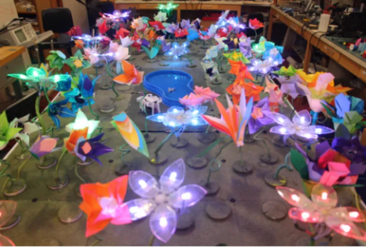
Fig. 1. The Robot Garden is a heterogeneous collection of distributed robots, including 100 actuated origami flowers and mobile foldable insects.
• the presentation of a fully functional robot garden, and • analysis of the system in terms of educational and
broader impact.
A high level description of the garden is outlined in section II, followed in section III by the process by which its mechanical system was realized. Section IV contains a de-scription of the electrical and electromechanical systems used to imbue the robots with actuation, and the algorithms and software used to control the robots are presented in section V. Section VI presents some results from the operation of the robot garden, followed by an analysis of its behavior in terms of education in section VII, and more general conclusions in section VIII.
II. ROBOT GARDEN OVERVIEW
The Distributed Robot Garden System is a multi-robot system consisting of flower robots, crawling robots and swimming robots. In contrast to the robot garden in [11], not only are there robots amongst the plants in the garden, but the plants themselves are robotic devices. This is similar to the artistic sculpture “Electronic Garden #2” described in [1] and the interactive display of [12].
The robots in this garden interact with a user through a user interface on a Bluetooth-enabled device and robots can either be controlled individually or as a group. The robot garden integrates printable robot and pouch motor technologies with distributed software techniques to produce a visually captivating educational tool.
The garden consists of 100 printable robotic flowers of eight different varieties. The movement of each flower is
Fig. 2. A self-folding crane is magnetically controlled across the surface of a pond.
controllable using a printable pneumatic actuator called the pouch motor [13]; by inflating and deflating a polyethylene pouch, flowers can open and close. At least one flower per tile also features RGB LED lights and can therefore change color on demand. The robotic flowers span 16 separate tiles in the garden structure, and control of flower movement and color can be per flower, per tile, or distributed across the entire garden.
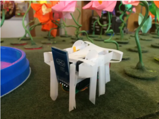
We expanded our distributed system to integrate additional different types of printable robots on the same platform. These robots include an insect-type crawling robot (Fig. 3) [14] and a remotely controlled swimming crane robot on a pond placed in the center of the garden (Fig. 2).
The insect robot shown in Fig. 3 is fabricated using a print-and-fold technique. The insect’s structural, electrical, and software designs were auto-generated using a robot compiler [14]. The insect crawls around the garden, and its speed and direction are managed by an embedded Arduino Pro Mini and can be remotely modified by an operator using a smartphone user interface.
Control of the swimming robot is managed by applying a magnetic field remotely. We fabricated an origami-crane robot equipped only with a permanent magnet for actuation and fabricated using a print-and-self-fold technique [15]. The design utilizes a crease pattern proposed in [16], and was folded by applying heat in an oven. The remote magnetic control is implemented by four electromagnetic coils situated under the pond. Each coil is tilted 45 degrees relative to a central symmetric axis [17]. This configuration enables the crane robot to move in an arbitrary x-y direction while floating on water.
III. ROBOT GARDEN DESIGN AND FABRICATION All garden components are modules that can be easily added or removed from the system. These modules include the tiles that comprise the garden structure, each of the 100 robotic flowers, and other robots in the garden. The garden bed is 86⇥170cm and has six rows and three columns for a total of 18 tiles. Tiles are 28⇥28cm. Two tiles in the center
Fig. 3. An insect manufactured using print-and-fold techniques can crawl around the flowers.
of the garden are empty and are reserved for display of the swimming crane robot and the insect robot. The other 16 tiles (Fig. 4 (a)) are full of the robotic flowers and some empty connectors that are camouflaged with the tiles to avoid overcrowding in the garden. Each robotic flower in the garden is fabricated using print-and-fold mechanical design and novel printed pouch motor actuators [13]. Each of the 16 operational tiles has eight holes for interchangeable flower connectors, allowing the garden to be easily reconfigured (Fig. 4 (b)).
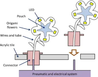
One tile of robotic flowers has eight primary mechanical and electrical components (Fig. 5), which are as follows:
• Origami flower: Flowers are made of thin color papers
or thin acrylic sheets, 0.2 mm in thickness. The designed flowers are manually cut and folded.
• Pouch motors: Pouch motors are soft pneumatic
actu-ators used to actuate the blooming motion of petals. Their shape, dimension and patterns are programmed on a desktop computer and manufactured using a heat sealing method [13].
• Tubes and wires: Tubes and wires provide air pressure
and electrical signals to the flowers. They are coated with green-colored liquid rubber, which is cured at room temperature for a day after application. The rubber coating increases the stiffness of the stem so the flower and stem can maintain their pose.
• Connector: The robotic flower connector has three main
functions. First, it fixes the rubber-coated stem to the plate. Second, it connects the air pressure and electrical signals from the system below the tile to the air pouches and LEDs on the flower. Finally, it allows flowers to be interchangeable throughout the garden. This accommo-dates multiple configurations of flowers in the garden and allows a broken flower to easily be exchanged for a new flower (see the right flower in Fig. 5). Connectors are made by using a 3-D printer or rubber molds.
• Acrylic plate: The plate has eight holes to support
robotic flower connectors. The position of holes can be programmed using a CAD tool and rapidly
manufac-Fig. 4. Robot Garden Tiles (a) The robotic garden bed consists of 16 identical modular tiles. (b) Each modular tile can hold 8 flowers.
Fig. 5. A schematic figure (side-view) of a pouch-actuated robotic flower. Each robotic flower has one connector, wires, a tube, a printable and inflatable pouch, and some flowers have LEDs. The pneumatic and electrical system below the acrylic tile provide air pressure and electric signals to the pouch and LEDs in the flower. Flowers are interchangeable throughout the garden.
tured by using a laser cutter.
• Pneumatic and Electrical System: Each tile has one
pneumatic and electrical setup to actuate the pneumatic pouches and LEDs inside the flowers. These flower actuation and control systems are detailed further in sections IV and V.
The above components are mass-producible using a laser cutter, a 3-D printer, a computer-controlled heat sealing machine, and molds. Using these tools, we can manufacture garden components quickly and in large quantities.
We developed a pouch-motor manufacturing method to allow rapid design, fabrication, and iterative design modifi-cation of the pouch motors [18]. The detailed process is as follows: a 2D pouch motor CAD design is converted into Numerical Control (NC) codes, which are then sent to a custom-made CNC machine to make the pouch systems. This machine “draws” pouch patterns onto two layers of 4mm thick polyethylene film simultaneously using the heat sealing machine which incorporates a heated soldering iron [18].
Our versatile fabrication process also enables multilayer pouch motors to be made simply layer by layer. We added
Fig. 6. Fabrication method of a two-layer pouch motor.
four alignment features to the CNC machine mounting board to support this capability. We make the multilayer pouches by creating “air doors” in between neighboring pouches first, and then thermally bonding the top pouch while fiberglass separates it from the bottom pouches. Using this rapid fabrication technology we created 100 flower robots that can be used as modules populating a control and programming environment consisting of 16 tiles. The flower robots can be used to visualize physically classical graph and networking algorithms (e.g. to visualize depth first search or broadcast, see section V part E), or programmed to display specific global behaviors (e.g. to create waves.)
IV. ROBOT GARDEN DESIGN AND ACTUATION The robotic flowers exhibited in the garden are all actuated by pouch motors [13]. We made eight types of flowers, seven made by folding origami paper and one made with an acrylic sheet and decorated with LEDs. The robotic flower types and numbers of each type of flower in the garden are as follows: robotic tulip (20) , robotic lotus (25), robotic lily (15), robotic spiral flower (11), robotic bird of paradise (2), robotic fireworks flower (3), robotic clematis (3) and robotic LED flower (40). In order to facilitate different foldings and to achieve different blossom effects, pouch motors were tailored to the different designs and actuation mechanisms. The flower and pouch motor types are shown in Fig. 7. Each robotic flower has one pouch actuator, allowing one degree of freedom. Additionally, we have included the crane robot and insect robot in the center of the garden. The following list describes each type of robot in the garden and its motion:
• Robotic Tulip: The robotic tulip has a pouch hidden
inside the side petals. When the pouch is inflated, the originally folded pouch unfolds and opens up the flower. Some robotic tulips have an LED in the center that allow these flowers to light up and change colors. See Fig. 7 (A).
• Robotic Lotus: Inside the robotic lotus, a smaller square
pouch is stacked on top of a larger square pouch. When the pouches are inflated, they push up the stamen and pistils. See Fig. 7 (B).
• Robotic Flower Lily: The robotic flower lily has
mul-tiple pouches connected in a cross beneath the petals. Although the design looks like a linear mode pouch system as introduced by Niiyama et al. [13], it acts like a discrete rotational mode single pouch. This is because the entire pouch is adhered to the flower petals, not only the ends of each of the pouch stems. When pouches are inflated, the individual pouches on the pouch stems “bend” the adhered paper petals to open the flower. Some robotic flower lilies have an LED in the center that allow these robots to light up and change colors. See Fig. 7 (C).
• Robotic Clematis: The robotic clematis uses the same
pouch motor design as the robotic lotus. The stamen and pistils are pushed outward with pouch inflation. See Fig. 7 (D).
• Robotic Spiral Flower: Unlike other robot flowers on
which pouch motors are adhered onto folded origami structures, we took a very different approach to make spiral flowers. For each spiral flower, we folded 12 simple petals and adhered them onto a spiral shape pouch. When the pouch inflates, the length of the spiral changes and presents a twisting effect on petals. See Fig. 7 (E).
• Robotic Bird of Paradise: The actuation mechanism on
the robotic bird of paradise is similar to the method used for the robotic lotuses in that pouches are stacked. In this case, the bottoms of the individual pouches are bonded together. When they are inflated, the pouches separate and open the petals. See Fig. 7 (F).
• Robotic Fireworks Flower: Like the robotic flower lily,
the pouch motors for the robotic fireworks flower are hidden beneath the petals of the flower. The change in shape of the pouch during inflation pushes the flower open. See Fig. 7 (G).
• Robotic LED Flower: Unlike the other flowers, the LED
flower is made with acrylic sheets. There is one LED on each petal. The blooming motion of the petals is actuated by rotational mode single unit pouch motors, discussed in detail by Niiyama et al. [13]. The wires connecting the LEDs are wrapped around the stem and attached to the plug connector. See Fig. 7 (H).
• Robotic Crane: The robot crane is printable and
self-folding using a small oven. The crane contains a magnet and is actuated using four electromagnetic coils below the pond section of the garden where it swims. See Fig. 2.
• Robotic Insect: The robot insect is a robot developed
using a robot compiler [14] and is fabricated using a simple print-and-fold process. The insect comprises a chassis, an Arduino Pro Mini board and continuous rotation servos for control and actuation of the legs. See Fig. 3.
We use electrical pumps and valves to control the actuation of robot flowers. Each tile has 8 flower connections, 4 pneumatic solenoid valves, and a single pump; pairs of flower
Fig. 7. Pictures of inflated flowers and corresponding pouch motor designs. The locations of the pouches are marked in yellow. (A)Tulip (B) Lotus (C) Flower Lily (D) Clematis (E) Spiral Flower (F) Bird of Paradise (G) Fireworks Flower (H) LED Flower
Fig. 8. Pneumatic connections. The ports on the valve from top to bottom are: exhaust, supply and output.
ports are linked together through a solenoid valve to the air supply. The valve connects the supply port to the output port during the inflation phase to allow air to come into the pouch from the pump. It connects the exhaust port to the output port during the deflation phase to allow air to exhaust in order to deflate the pouch. Fig. 8 shows the pump and valve connections.
V. ROBOT GARDEN CONTROL
Each of the 16 tiles in the garden can support control of up to eight flowers with LEDs and pouch motors. Each tile in the garden is controlled using an Arduino Mega2560 microcontroller equipped with additional custom PCBs de-signed to service all flower pumps and LED connections. Each Arduino board can be connected to a serial Bluetooth chip to allow Bluetooth communication between the tile and a computer or smartphone device running a Graphical User Interface developed in Python. We use the PyBluez library [19] for Python to facilitate communication between
the Bluetooth-connected device and the Bluetooth chips in the garden. Additionally, the Arduino boards are connected in a wire mesh network; each Arduino can communicate with each of its adjacent neighbors via a one-wire serial protocol. This design therefore allows for both distributed communications as well as centralized control. The intent is that a limited number of tiles will have Bluetooth connec-tions to the controller, and all other tiles will react solely to inter-tile communications and thus create a distributed mesh network. Algorithms are discussed below for tile self-addressing, communication, and demonstration of distributed behaviors - in these examples, only a single tile is equipped with Bluetooth functionality.
A. Computational Hardware
The hardware components required for computation and control of the garden include the following for each tile: an Arduino Mega2560 board, two custom printed circuit boards, a Bluetooth chip, and wired connections to pumps, valves, LEDs and to other Arduino boards. In addition, a power supply is required to provide power to all Arduinos and pumps and a bluetooth-enabled computer that can run Python is required for external control of the garden using the GUI. The computational hardware used for the robot garden is extensible. The custom printed circuit boards allow the Arduino to service additional flowers or sensors, so hardware can be reused if there are design changes in future versions of the garden.
B. Graphical User Interface
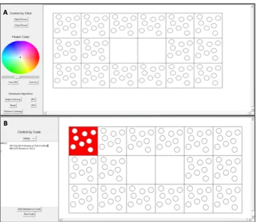
We developed a Graphical User Interface (GUI) in Python so that inexperienced users can easily control the garden. The Graphical User Interface shows the layout of the garden and has two components: the “Control by Click” component and the “Control by Code” component. The two components of the GUI are shown in Fig. 9. Each tile begins by running in “Automode” in which flowers inflate, deflate and change LED colors in a uniform pattern across all tiles. Once a command is sent to a tile through the GUI, that tile exits “Automode” and is controllable only through the user interface.
The “Control by Click” component has buttons that allow the user to open and close the flowers using the pouch motors, a color wheel that allows the user to select a color for LEDs on the flowers, and buttons to turn the LEDs off and on. Additionally there are buttons that allow users to demonstrate distributed behaviors throughout the garden. Users can select one or multiple flowers or tiles to control and then select a command on the interface, and the selected tiles or flowers will execute the provided command.
The “Control by Code” component of the GUI allows users to select a flower or tile and a command from a drop-down menu. Users then add their selected tile and command to the text by clicking the “Add Selection to Code” button and can run the commands they have chosen in sequence using the “Run Code” button.
Fig. 9. The robots can be controlled via a GUI over Bluetooth using either (A) an intuitive “Control by Click” component or (B) a “Control by Code” component for more advanced users.
Both components of the GUI can be run on a tablet computer, allowing use of a touch screen interface for control of the garden. Additionally, we developed a simple Android application to allow users to send commands directly to the garden over Bluetooth using a smartphone.
C. Mesh Network and Addressing
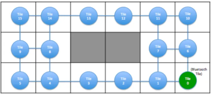
Control of the garden through the GUI requires commu-nication between a computer and all tiles in the garden. To support maximum scalability, we decided to establish a minority of tiles (in this implementation, a single tile) as Bluetooth tiles with connection to the computer and to create a mesh network including the remaining tiles in the garden using one-wire serial connections for information distribution. In this setup, new tiles are easily added to or removed from the garden network. Each tile in the garden is a node in the mesh network and is connected to the orthogonal neighboring tiles in the garden grid structure, shown in Fig. 10. The two center tiles are not included in the network to allow the pond with the crane robot and the insect robot to be displayed. The SoftwareSerial library for Arduino [20], modified to allow communication over a single wire and to manage multiple simultaneous connections, is used to implement the communication between Arduino controllers in the network.
To allow tile-to-tile communication and relay of com-mands throughout the garden, we developed a distributed automatic addressing scheme so each node in the network determines a unique address. On startup, each tile deter-mines its local connectivity (which neighbors are present) in the mesh network and communicates with its neighbors to determine an appropriate address such that each tile in the network ends up with a different address. Currently we use a specific addressing pattern for communication with the graphical user interface, so we give one tile a seed value
Fig. 10. Each tile in the garden can communicate with its immediate neighbors via serial. One tile can communicate with an external GUI via Blueooth.
which provides the basis for all other assigned addresses in the garden. For our current addressing scheme, the number of required exchanged messages scales linearly with the size of the garden.
D. Arduino-to-Arduino Communication
When a specific flower or tile and a command are selected using the GUI, the command is routed through the Bluetooth-connected tile to the appropriate tile in the mesh network. When a tile receives a command, if it is its own, it will simply execute the command. Otherwise it will send the command to the next tile it thinks is in the optimal path to the goal tile given its local knowledge. If that chosen tile is in the direction from which the message was sent, the tile can infer there was an obstacle along the optimal path and can choose the next best route. With the current garden structure and using this routing algorithm, any tile can be reached in a maximum of eight hops (this includes rerouting around the pond obstacle).
E. Distributed Algorithms
The robot garden can be used to introduce young students to programming, networking, and robot control in a colorful way. The garden can be used to visualize the behavior of classical graph algorithms and distributed graph algorithms. The execution sequence of such algorithms can be visualized by carefully programming the color of the flowers in the garden. The over 100 robots in this system (which can be easily extended to larger numbers) provides a large scale plat-form for experimenting with robot control. We implemented a flooding algorithm, a graph coloring algorithm, depth first search (DFS), breadth first search (BFS), and a distance coloring algorithm in the garden as examples. Six buttons in the GUI, a “Flood” button, a “Graph Coloring” button, a ”DFS” button, a ”BFS” button, a ”Distance Coloring” button and a ”Reset” button allow users to observe the behaviors of these algorithms throughout the garden and reset the flowers afterwards.
When the “Flood” button is selected in the GUI and the flooding algorithm is called, a command is first sent to the Bluetooth-connected tile to trigger the start of the flooding behavior. On the first tile, all flowers are inflated, and the tile sends the “flood” command to all of its neighbors. When
the neighbors receive the command, they inflate all of their flowers and pass the command on again. A boolean value is used to keep track of whether or not a tile has already received a flooding command to prevent infinite looping in cycles in the garden. After 30 seconds, enough time for the algorithm to traverse the entire garden, the boolean value on each tile is changed back to its original value, allowing the tile to receive the “flood” command if it is sent again.
Graph coloring is a well-studied problem which aims to assign colors to the nodes of a graph such that no two adjacent nodes have the same color, and to use the fewest possible colors. This can be implemented as a distributed algorithm, and lends itself to a visual demonstration. In the case of the robot garden, each tile is considered a node and each node is considered connected to its eight surrounding tiles (the algorithm creates a virtual link between diagonal tiles since no physical wires link them). Since the graph formed by the tiles is chordal, a perfect elimination ordering can be found [21] and a greedy algorithm can determine an optimal coloring. When the “Graph Coloring” button is selected, the Bluetooth tile initiates a distributed implementation of a greedy algorithm; upon receiving the color command, each tile chooses a color not used by its neighbors and forwards the command to a new neighbor. Once all tiles have received the command and chosen a color, an optimal coloring is achieved as shown in Fig. 11. The running of this algorithm can optionally be slowed down to illustrate its procession and the various choices made.
Two common search algorithms can be displayed in the garden through the selection of either the ”DFS” button for depth-first search or the ”BFS” button for breadth-first search. In both cases, a start and goal tile can be specified by user selection in the GUI, and the selected command is routed through the Bluetooth tile to the start tile using the tile addresses assigned during startup. A tree is created with the start tile as the root node and orthogonally neighboring tiles as child nodes. All LED flowers begin blue, and as the search algorithms traverse the garden, flowers on tiles that have been searched turn red. When the goal tile is found, its LED flowers turn green all flowers in the path to it turn green as well, showing the route that was traversed to locate the goal tile. The series of pictures in Fig. 12 shows how BFS is visualized in the garden as an example.
The distance coloring algorithm that runs when the ”Dis-tance Coloring” button is selected in the GUI creates a tree with the Bluetooth-connected tile as the root node and the neighboring tiles as child nodes, as in the search algorithms. When the distance coloring algorithm runs, the LED flowers on the root node tile turn violet, the LED flowers on tiles in subsequent levels of the tree turn increasingly redder colors on the color scale, and the LED flowers on the tiles at the deepest level of the tree turn red. The distance coloring algorithm is essentially the same as the BFS algorithm, except that flowers on searched tiles turn an appropriate color based on the number of hops they are from the root node rather than all red.
Fig. 11. A distributed greedy graph coloring algorithm finds an optimal 4-coloring of the robot garden (each tile is considered connected to its possibly 8 surrounding neighbors).
Fig. 12. Breadth-first Search propagating in the robot garden.
LED flowers in the garden back to their starting blue color, so a new algorithm can be run in the garden.
VI. SYSTEM PERFORMANCE
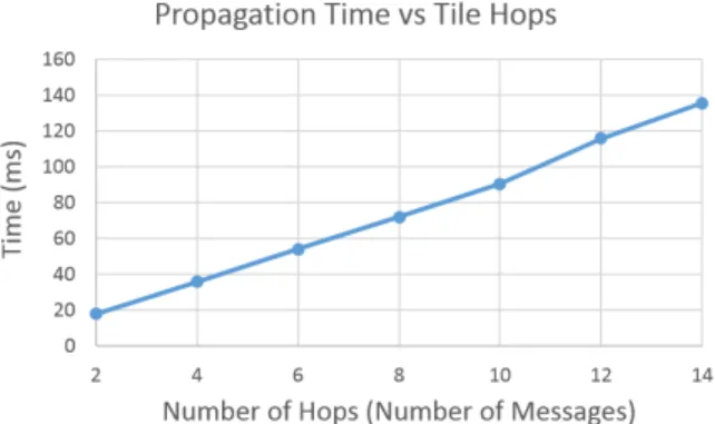
To compare our distributed system, which facilitates scal-ability, with a system using a centralized controller, we analyzed the total time required to send a command to each tile in the garden network. If a central controller were connected to each individual tile, the communication delay for a given command would be the round-trip time of sending and receiving a message with one tile over Bluetooth. This was found to average 42.07ms with a standard deviation of 8.16ms over 30 trials. The extra time incurred by making the garden distributed rather than centralized can be evaluated by measuring the round-trip time of sending and receiving a message between tiles using the command-routing algorithm mentioned in section V, part D. This added delay, as a function of the tile hops, is illustrated in Fig. 13. Each hop currently takes an average of 9.20ms with a standard deviation of 0.32ms (over 30 trials). This can be reduced in the future by adjusting the serial baud rate and optimizing the communication protocol.
VII. EDUCATIONAL APPLICATIONS
The robot garden can act as a platform for education and art, particularly focused on teaching computational thinking. The garden allows users to see their commands or code running in the physical world, linking programming to the real world. We believe that the robot garden comprises a rich suite of elements that could be the basis for a programming curriculum for the age range spanning from young children to high school students.
Fig. 13. Propagation time was measured as a function of hops to determine the delay obtained by using distributed communication as opposed to a central controller. Only even-numbered hops are plotted since round-trips were evaluated.
Through the “Control by Click” portion of the user inter-face, users can either control the garden directly by clicking on flowers or tiles and choosing commands or they can click on one of the algorithm visualization buttons to see algorithms demonstrated in a visual way using actuation and changing of colors of flowers in the garden. This part of the GUI acts as a teaching tool for basic algorithmic concepts. So far, we have visually demonstrated five algorithms in the garden, and by leveraging the capabilities of the flower de-sign and infrastructure of the system, many other distributed and graph traversal algorithms can be depicted in interesting ways.
Through the “Control by Code” section users are able to “create art” using basic programming concepts. Currently users select a tile or tiles and a command and press the “Add to Code” button, and they can see their commands pop up in the text box in sequential order. Selecting “Run Code” runs the commands they have chosen in sequence in the garden, demonstrating basic sequential programming concepts. In the future, we envision adding functionality to the “Control by Code” section that allows users to use logical statements and looping in their garden code with the aim of teaching these additional programming concepts through garden use.
In addition to adding functionality to the GUI, we plan to develop end-to-end programming curriculum materials that leverage the capabilities of the garden to teach computational thinking. We have already developed a versatile curriculum for middle school students that covers basic programming concepts including reactive behaviors and finite state ma-chines. We have adapted this curriculum to both Lego Mindstorms robots [22] and the MIT SEG robot [23]. We plan to adapt the curriculum to the robot garden by adding basic sensing to the tiles and using the GUI we have already created. In addition to using materials we already have, we will add a unit covering basic algorithms to the curriculum, making use of the visual algorithm demonstration capabilities of the garden.
The robot garden has been operational and used regularly for six months so far, and in that time it has been used for three major demo events and approximately a dozen
other smaller demo events. In December 2014, the robot garden was displayed at an ”Hour of Code” event held at MIT’s Computer Science and Artificial Intelligence Lab. At the event, 150 high school students interacted with the garden using both the ”Control by Click” and ”Control by Code” components of the GUI. Groups of approximately 20 students first took turns selecting tiles in the garden and com-mands for flowers on each tile using the ”Control by Click” interface. They then worked together to unscramble high-level pseudocode for the graph coloring algorithm which they entered into the ”Control by Code” interface to see the algorithm run in the garden. In March 2015, another group of high school students will be interacting with the garden in a similar capacity, and in the future we plan to invite additional students from local schools to use the garden and provide feedback on the garden user interface and curriculum.
VIII. CONCLUSIONS AND FUTURE WORK An initial goal of the distributed robot garden system was to showcase state-of-the-art rapid prototyping techniques for robot creation. The system employs many such technologies including pouch motor actuators, self-folding robots, and robots created using the robot compiler. However, though rapid fabrication techniques were used to produce the pouch motors for actuation as well as the structures for the LED flowers, creating the intricate origami flowers called upon additional manual assembly steps for the sake of aesthet-ics. Further development of advanced fabrication techniques could serve to reduce the build time of new robots for the garden.
Additionally, the overall system was designed to be ac-cessible to the general public, for use in museum exhibits or educational installations. We developed an educational environment that teaches basic programming concepts and algorithms, and we will continue to work towards an end-to-end programming curriculum for middle and high school students. We will also work towards development of an Android GUI for control of the garden via a smartphone or tablet, we will incorporate additional sensing for increased interactivity with users, and we will explore the possibility of using smaller microcontrollers and different software envi-ronments for increased portability and compatibility. Finally, we will work towards developing a more portable version of the garden made up of smaller flower modules, making the garden’s benefits as an educational tool more accessible to schools and the general public.
Overall, the distributed robot garden achieved many of its objectives, and its extensibility allows for many possibilities for future additions to the distributed robot system.
ACKNOWLEDGMENT
This work was funded in part by NSF grants 1240383 and 1138967 and NSF Graduate Research Fellowship 1122374, for which the authors express thanks.
We also thank Xu Sun for his kind and insightful instruc-tion, and Justin Cheung, Chris Cho, Samantha Castellanos,
and Steven Guitron for helping with manufacturing of the hardware system.
REFERENCES
[1] E. Kac, “Towards a chronology of robotic art,” Convergence: The International Journal of Research into New Media Technologies, vol. 7, no. 1, pp. 87–111, 2001.
[2] L. Pagliarini and H. Hautop Lund, “The development of robot art,” Artificial Life and Robotics, vol. 13, no. 2, pp. 401–405, 2009. [3] T. R. Flowers and K. A. Gossett, “Teaching problem solving,
comput-ing, and information technology with robots,” J. Comput. Sci. Coll., vol. 17, no. 6, pp. 45–55, May 2002.
[4] H. Kitano, S. Suzuki, and J. Akita, “Robocup jr.: Robocup for edutainment,” in Proc. IEEE Intl. Conf. on Robotics and Automation (ICRA 2000), Apr. 2000, pp. 807–812.
[5] X. Yu, D. Assaf, L. Wang, and F. Iida, “A case study in soft-bodied locomotion,” in IEEE Workshop on Advanced Robotics and its Social Impacts (ARSO), 2013, pp. 194–199.
[6] D. Assaf and R. Pfeifer, “Embedit - an open robotic kit for education,” in Eurobot Conference, 2011, pp. 29–39.
[7] “USFIRST.org,” http://www.usfirst.org, 2014, [Online; accessed 01-Oct-2014].
[8] “Ultra affordable educational robot project,” http://robotics- africa.org/afron-design-challenges/ultra-affordable-educational-robot-project.html, 2014, [Online; accessed 01-Oct-2014].
[9] C. Breazeal, A. Brooks, J. Gray, M. Hancher, J. McBean, D. Stiehl, and J. Strickon, “Interactive robot theatre,” Commun. ACM, vol. 46, no. 7, pp. 76–85, Jul. 2003.
[10] “LEGO.com Mindstorms,” http://mindstorms.lego.com, 2014, [Online; accessed 01-Oct-2014].
[11] N. Correll, N. Arechiga, A. Bolger, M. Bollini, B. Charrow, A. Clay-ton, F. Dominguez, K. Donahue, S. Dyar, L. Johnson et al., “Building a distributed robot garden,” in Intelligent Robots and Systems (IROS 2009). IEEE, 2009, pp. 1509–1516.
[12] D. Holstius, J. Kembel, A. Hurst, P.-H. Wan, and J. Forlizzi, “In-fotropism: Living and robotic plants as interactive displays,” in Pro-ceedings of the 5th Conference on Designing Interactive Systems: Processes, Practices, Methods, and Techniques, ser. DIS ’04. New York, NY, USA: ACM, 2004, pp. 215–221.
[13] R. Niiyama, D. Rus, and S. Kim, “Pouch motors: Printable/inflatable soft actuators for robotics,” in Proc. of IEEE International Conference on Robotics and Automation, 2014.
[14] B. S. A. M. Mehta, J. DelPreto and D. Rus, “Cogeneration of mechani-cal, electrimechani-cal, and software designs for printable robots from structural specifications,” in IEEE/RSJ International Conference onIntelligent Robots and Systems (IROS), 2014.
[15] S. Miyashita, C. D. Onal, and D. Rus, “Self-pop-up cylindrical structure by global heating,” in IEEE/RSJ International Conference on Intelligent Robots and Systems (IROS), 2013.
[16] S. M. Felton, M. T. Tolley, B. Shin, C. D. Onal, E. D. Demaine, D. Rus, and R. J. Wood, “Self-folding with shape memory composites,” Soft Matter, vol. 9, pp. 7688–7694, 2013.
[17] S. Miyashita, S. Guitron, M. Ludersdorfer, C. Sung, and D. Rus, “An untethered miniature origami robot that self-folds, walks, swims, and degrades,” in IEEE International Conference on Robotics and Automation (ICRA), submitted.
[18] R. Niiyama, X. Sun, C. Sung, B. An, D. Rus, and S. Kim, “Pouch motors: Printable soft actuators integrated with computational design,” International Journal of Robotics Research, submitted.
[19] “PyBluez,” https://code.google.com/p/pybluez/, 2014, [Online; ac-cessed 25-Jul-2014].
[20] “SoftwareSerial Library,” http://arduino.cc/en/Reference/softwareSerial, 2014, [Online; accessed 25-Jul-2014].
[21] R. E. Tarjan and M. Yannakakis, “Simple linear-time algorithms to test chordality of graphs, test acyclicity of hypergraphs, and selectively reduce acyclic hypergraphs,” SIAM Journal on computing, vol. 13, no. 3, 1984.
[22] “An Expedition in Computing for Compiling Printable Programmable Machines,” http://ppm.csail.mit.edu/Education%20and%20OUtreach, 2013, [Online; accessed 25-Sep-2014].
[23] “MIT SEG Curriculum,” https://sites.google.com/site/mitprintablerobots /curriculum, 2014, [Online; accessed 25-Sep-2014].