Comparison of Analytical and Numerical Approaches for Determining Failure of Ring-Stiffened Cylindrical Shells
by
Michael W. Temme B.S. Electrical Engineering
South Dakota State University, 1990 MBA
University of Nebraska-Lincoln, 1997
Submitted to the Department of Ocean Engineering and the Department of Mechanical Engineering in Partial Fulfillment of the Requirements for the Degrees of
Master of Science in Naval Architecture and Marine Engineering and
Master of Science in Mechanical Engineering at the
Massachusetts Institute of Technology June 2003
C 2003 Michael W. Temme. All rights reserved.
The author hereby grants to MIT permission to reproduce and to distribute publicly paper and electronic copies of this thesis document in whole or in nart
Signature of Author
Certified by
Department of Ocean Engineering and the Department of Mechanical Engineering May 12, 2003 David V. Burke, Senior Lecturer Department of Ocean Engineering Thesis Supervisor
Certified by
Accepted by
Nicholas M. Patrikalak is, Professor of Ocean and Mechanical Engineering awasaki Professor of Engineering Thesis Reader f-vh j'Triantafytou~, Professor of Ocean Engineering Vai nepartment Committee on Graduate Students artment of Ocean Engineering
Accepted by
Am A. Sonin, Professor of Mechanical Engineering Chairman, Department Committee on Graduate Students Department of Mechanical Engineering
MASSACHUSETTS INSTITUT-E-OFTECHNOLOGY
AUG 2 5 2003
Comparison of Analytical and Numerical Approaches for Determining Failure of Ring-Stiffened Cylindrical Shells
by
Michael W. Temme
Submitted to the Department of Ocean Engineering and the Department of Mechanical Engineering in Partial Fulfillment of the Requirements for the Degrees of
Master of Science in Naval Architecture and Marine Engineering and
Master of Science in Mechanical Engineering
ABSTRACT
The thesis compares the analytical solution, two marine classification society design rules, and numerical analysis against experimental results for predicting the failure modes (general instability, axisymmetric buckling, and asymmetric collapse of the shell) and failure pressures of ring-stiffened cylindrical shells.
The analytical solution is first summarized based on several sources. Design rules for the classification societies are then presented with brief explanations for each one. The design rules used are: American Petroleum Institute (Bulletin on Stability Design of Cylindrical Shells, API Bulletin 2U, Second Edition, October 2000) and Det Norske Veritas (Buckling Strength of Shells, October 2002). The numerical analysis was performed using the software package, Method For Analysis Evaluation and Structural Optimization (MAESTROTM, version 8.5, Proteus
Engineering).
The United States Navy Naval Sea Systems Command, Submarine Structural Integrity Division supplied experimental data for four test cylinders that covered the failure modes and allowed comparison between experimental and analytical / numerical results.
The comparison of experimental to predicted data found the design rules and numerical solution performed adequately in predicting asymmetric buckling and general instability failure modes, but the predictions for failure pressure were unsatisfactory. The design rules were overly conservative in their predictions of failure pressure due to the semi-empirical solutions used in the rules. The numerical solution was only slightly better for the same failure pressure
predictions. The results indicate the predicted failure pressure for a cylinder is closely tied to the size and dimensions of the cylinders used for determining the empirical solutions. These results should be further explored to determine causes and corrections.
Thesis Supervisor: David V. Burke Title: Senior Lecturer
Thesis Reader: Nicholas M. Patrikalakis
Title: Professor of Ocean and Mechanical Engineering Kawasaki Professor of Engineering
Acknowledgements
I would like to thank Mr. William Will of the Naval Sea Systems Command, Submarine
Structural Integrity division for providing the experimental data for the thesis and providing invaluable knowledge into the mechanics of cylindrical failures.
I would like to thank Prof. Owen Hughes of the Aerospace and Ocean Engineering
Department, Virginia Tech for providing me with information and advice on MAESTROTM and the source code behind the program.
I would also like to thank Dr. David Burke for not only being a very supportive advisor
and providing the impetus for the thesis, but for giving much needed and timely guidance throughout the analysis and writing processes.
This thesis is dedicated to:
My wife: Holly A. Temme
Table of Contents
Table of Contents... 5
List of Figures ... 8
List of Tables ... 8
CH APTER 1: Introduction and Problem Statem ent ... 9
1.1 D efinition of Failure M odes... 9
1.2 Literature Search... 10
1.3 Previous W ork ... 11
1.4 Problem Statem ent ... 12
CHAPTER 2: Approach ... 13
2.1 Analysis Techniques ... 13
2.1.1 Analytical M ethods... 13
2.1.2 N um erical M ethod ... 14
2.2 D esign Rules Exam ined... 14
CH A PTER 3: Basics of Ring-Stiffened Cylindrical Shells... 15
3.1 N om enclature...15
3.2 D im ensions...15
3.3 Stresses in Cylinders...17
CHAPTER 4: A nalytic Solution... 19
4.1 Axisym m etric Y ield...20
4.2 A sym m etric Buckling... 24
4.3 G eneral Instability ... 25
5.1 M AESTROTM Overview ... 28
5.2 Cylindrical M odels... 29
5.3 Failure M odes Evaluated ... 29
CHAPTER 6: Classification Society Design Rules... 31
6.1 Am erican Petroleum Institute (API)... 31
6.1.1 Lim itations and Applicability... 32
6.1.2 Local Shell Buckling... 32
6.1.3 General Instability... 34
6.2 Det N orske Veritas (DNV)... 35
6.2.1 Lim itations and Applicability ... 36
6.2.2 Shell Buckling... 36
6.2.3 Panel Ring Buckling... 38
CHAPTER 7: Results ... 41
7.1 NAVSEA Test Cylinders... 41
7.1.1 Cylinder 1d... 42
7.1.2 Cylinder 1f... 43
7.1.3 Cylinder 2.a... 44
7.1.4 Cylinder 2.c... 45
7.2 Calculation to Experim ental Com parison... 46
7.2.1 Cylinder 1.d Results... 46
7.2.2 Cylinder 1.f Results ... 48
7.2.3 Cylinder 2.a Results ... 50
7.3 Com parison to Previous W ork... 53
CH A PTER 8: Conclusions ... 55
8.1 Com parative A nalysis Review ... 55
8.2 A greem ents and D iscrepancies... 56
8.3 A pplications of the Results ... 58
8.4 Further A reas of Study ... 59
List of References ... 61
A ppendices... 63
A ppendix A : A nalytic Solution ... 65
A ppendix B : N um erical Solution... 91
A ppendix C: A PI (Bull 2U ) Solution... 123
List of Figures
Figure 1: G eneral Cylinder D im ensions ... 16
Figure 2: General Stiffener D im ensions ... 17
Figure 3: Failure Pressure Ratio versus Slenderness Ratio ... 20
Figure 4: Elem ent of a Cylindrical Shell ... 21
Figure 5: Test Cylinder 1.d Structural Dimensions ... 42
Figure 6: Test Cylinder 1.f Structural Dimensions... 43
Figure 7: Test Cylinder 2.a Structural Dimensions ... 44
Figure 8: Test Cylinder 2.c Structural Dimensions ... 45
Figure 9: Comparison of Predicted Failure Pressures for Cylinder 1d ... 47
Figure 10: Comparison of Predicted Failure Pressures for Cylinder lf... 49
Figure 11: Comparison of Predicted Failure Pressures for Cylinder 2.a ... 50
Figure 12: Comparison of Predicted Failure Pressures for Cylinder 2.c ... 52
List of Tables
Table 1: Comparison of Predicted Failure Mode and Pressure to Experimental Data ... 46Table 2: Predicted Failure Pressures and Modes for Cylinder 1d ... 47
Table 3: Predicted Failure Pressures and Modes for Cylinder 1f ... 48
Table 4: Predicted Failure Pressures and Modes for Cylinder 2.a... 50
Table 5: Predicted Failure Pressures and Modes for Cylinder 2.c... 51
CHAPTER 1: Introduction and Problem Statement
Recent interest in submersibles, submarines, and off-shore drilling rigs, has led to an increasing demand for structural design information on ring-stiffened cylindrical shells under uniform external pressure. The submarine designer today, has many analytical tools and methods available to help determine an optimum design. The widespread use of ring-stiffened cylinders in the marine industry has resulted in a significant amount of interest and activity being devoted to determining the failure pressure and characteristics of these cylinders. Marine
Classification Societies, such as the American Petroleum Institute (API), the American Bureau of Shipping (ABS), Det Norske Veritas (DNV), Germanischer Lloyd (GL) and others have
promulgated design rules to provide guidelines on designing and building stiffened cylinders for marine use. Other research has been conducted using numerical methods, such as finite element
analysis, to design and validate the structural adequacy of these ring-stiffened cylinders. By comparing these design methods, classification society design rules and numerical methods, with experimental results, the submarine designer can obtain a better understanding of the strengths and limitations of each method.
1.1 Definition of Failure Modes
Any discussion of cylinder failure analysis must first include definitions of the different failure modes. There are primarily three failure modes for ring-stiffened cylinders. They are axisymmetric yielding (AX) of the shell between stiffeners, asymmetric buckling of the shell between stiffeners (Lobar buckling) (L), and general instability (GI) of the shell and stiffeners. Axisymmetric yield is characterized by an accordion type pleat extending around the periphery of the cylinder, and generally occurs when the shell is relatively heavy and the frames are closely
spaced. Lobar buckling is characterized by inward and outward lobes or dimples, which may or may not develop around the entire periphery, and normally occurs when the shell is relatively thin and the frames are strong and widely spaced. General instability is characterized by the failure of both the shell and ring frames resulting in a dished-in surface. General instability normally occurs when the cylinder is relatively long, the shell is thin, and the frames are light.
1.2 Literature Search
The failure of cylinders exposed to external pressure has been studied for over a hundred years. As early as the 1850's, attempts were made to understand cylinder behavior by using experiments and empirical relationships [1]. The first analytic solution for a non-reinforced cylinder was presented by G. H. Bryan in 1888 [2]. During this time period, non-reinforced flues were observed to fail in fire-tube boilers at a pressure much less than the hoop stress, which led to a significant amount of research and interest in the subject. As a solution to this problem, stiffening rings or bulkheads were added to reduce the unsupported length of the tube [3]. The first analysis of a reinforced cylinder appeared in 1913 by R. V. Southwell, followed a year later
by a solution to the elastic buckling of a thin shell proposed by von Mises [1]. In 1934
Widenburg proposed a solution for asymmetric buckling that was independent of the number of lobes of failure, which made the solution easier to calculate [1]. Solutions for axisymmetric yield were first put forward by von Sanden and Gunther in 1920 [2]. In 1930, Viterbo presented a modified version of Sanden and Gunther's solution [2]. Finally, Pulos and Salerno
incorporated the previous work and presented a solution that included the Sanden and Gunther solution, the Viterbo modification and a term to account for the bending stress in the cylinder caused by the axial pressure [2]. For elastic general instability, the first reported analysis was
presented by Tokugawa in 1929. In 1954 A. R. Bryant developed a similar equation using a different methodology [1].
Analytical work from the 1950's onward has focused on obtaining solutions for different boundary conditions and more fully reconciling the analytic predictions with experimental results and more fully understanding the effects of initial cylinder imperfections. With the advent of the digital computer, programs like BOSOR 5 were developed that could use
numerical solutions to quickly and accurately predict failure pressures [1]. Further developments relating to numerical solutions led to the design of finite element programs, like ABAQUASTM, that could provide accurate stress and strain values for analyzing cylinder designs [1].
1.3 Previous Work
Tighter budgets in both industry and government have forced many large organizations to look for cost saving measures. One such perceived cost saving measure has been the outsourcing of many functions that were previously done within an organization. An example of this is found in the greater role that marine classification societies are playing in certifying and classifying naval vessels, not only for commercial interests, but also for governments. This interest has led many classification societies to develop extensive rules for certifying naval vessels and other marine structures. These rules can also be valuable tools for the submarine designer.
In a recent review of these classification society rules, D.J. Price used two marine classification design rules and compared them with analytical and experimental results for
ring-stiffened cylinders [4]. His work indicated that the two rules used (ABS and GL) were accurate for predicting axisymmetric yielding and lobar buckling when compared to experimental results.
However, they did not accurately predict failure by general instability. Further study was indicated in this area.
1.4 Problem Statement
In today's fiscally constrained environment, the submarine designer is faced with the challenge of providing the best structural design possible at the lowest cost. Detailed
confirmation models can increase costs not only through expensive fabrication but also time delays for constructing and testing the models. If the designer can use some of the tools
available, like classification society design rules and numerical solutions, to reduce or eliminate some of the confirmation models, there are significant cost savings to be anticipated.
This thesis used three of the design tools available (classification society design rules, numerical analysis tools, closed-form analytic solutions) to determine the failure modes and pressures for four experimentally tested ring-stiffened cylinders. The results from the design tools and the experiments were compared to determine the applicability and usefulness of these tools.
This thesis was not an exhaustive study of classification rules or of numerical analysis tools, rather it was an application of the design tools available. Comparisons and conclusions were drawn based on the results in order to provide the submarine designer a better
CHAPTER 2: Approach
For this thesis, emphasis was placed on exploring how various classification society design rules predicted failure of cylinders that were similar in design to modem submarine hulls. Similar design meant that the shell was relatively thick compared to the diameter of the cylinder. For comparison purposes, a numerical analysis was also performed on the same cylinders using a numerical analysis tool. In order to compare results with previous work, experimental failure data was obtained from the Naval Sea Systems Command (NAVSEA) Submarine Structural Integrity Division on the same test cylinders used in [4]. For consistency of analysis, the scope was limited to examining ring-stiffened cylindrical shells. The test cylinders used were selected to cover all three modes of cylinder failure, allowing for comparison of not only failure pressure but also failure mode.
2.1 Analysis Techniques
2.1.1 Analytical Methods
For the purpose of this thesis, the analytical methods include the classification society design rules and the closed-form analytic solutions. These analytical methods were programmed into MATHCADTM for consistency of approach, clarity of symbolic representation, and ease of calculation. Dimensions were input into each computer code, which provided failure pressures for each mode of failure. The lowest calculated pressure was considered the failure pressure with a corresponding failure mode. The failure modes and pressures were compared to experimental results with primary emphasis being placed on agreement of failure mode and secondary emphasis on failure pressure.
2.1.2 Numerical Method
To determine a numerical solution for the failure mode and pressure of a ring-stiffened cylinder, a numerical analysis tool was used. Analysis was performed using the Method for
Analysis Evaluation and Structural Optimization (MAESTROTM), version 8.5 distributed by
Proteus Engineering. Models of the test cylinders were created in MAESTROTM and subjected to increasing submergence pressure until failure occurred. The associated failure mode and pressure were considered the failure point for the model. Once again, failure modes and pressures were compared to experimental results with primary emphasis being placed on agreement of failure mode and secondary emphasis on failure pressure.
2.2 Design Rules Examined
There were two classification society design rules examined: The American Petroleum Institute (Bulletin on Stability Design of Cylindrical Shells, API (Bull 2U), Second Edition,
October 2000) [5] and Det Norske Veritas (Recommended Practice on Buckling Strength of
Shells, DNV-RP-C202, October 2002) [6]. The specific classification societies were selected due to their widespread use throughout the world and the availability of documented rules for ring-stiffened cylinders. Additionally, API was selected because of its widespread us in the U.S. while DNV was selected because of its widespread use in Europe. By using these two
classification societies, a concise snapshot of guidance relating to cylinder design could be obtained for a large segment of the marine industry.
CHAPTER 3: Basics of Ring-Stiffened Cylindrical Shells
The main structural body of most submarines and submersibles today, is constructed of a cylindrical parallel mid-body section. These cylinders are reinforced with ring-stiffeners
(frames) to provide additional strength to the shell that would collapse very easily if not
reinforced. A strong cylindrical structure is required for the large pressure differential between external hydrostatic pressure and internal pressure (normally maintained close to atmospheric pressure).
3.1 Nomenclature
Each of the analytical and numerical methods incorporated in this study used slightly different terminology for cylinder geometries and properties. When the analytical methods were programmed into MATHCADTM, the symbols used by the source document were generally used
in the program to avoid confusion between the published classification society rules and the programs. All of the analytical methods required the calculation of the moment of inertia of a combined plate and stiffener (I) using an effective shell length (Le). The formula for I, came from [7], while the formulas for Le were normally contained within the classification society rules. All stresses and pressures are in pounds per square inch (psi), lengths are in inches (in),
areas are in square inches (in2) and moments of inertia are in inches to the fourth (in4).
3.2 Dimensions
The dimensions of interest for analyzing ring-stiffened cylinders are related to the
cylinder (shell) itself and the ring-stiffeners (frames). Terms and definitions are listed below and represented in Figure 1 and Figure 2.
1) Cylinder Length (Lb): Overall length of the cylinder between supports. 2) Radius of Cylinder (R): Mean shell radius.
3) Shell Thickness (t, h): Thickness of cylinder shell plating.
4) Ring Spacing (Lf or L,): Unsupported length of shell from centerline to centerline of frames.
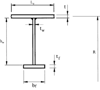
5) Web Height (hw): Length of the web from shell to the shell side of flange.
6) Web Thickness (tw): Thickness measured across web. 7) Flange Breadth (bf): Width of the flange.
8) Flange Thickness (tf): Thickness of flange measured perpendicular to breadth. 9) Faying Width (b): Contact width of ring frame to shell, normally equal to t,.
10) Effective Shell Length (Le): Usually some fraction of Lf specified in the individual solution. 11) Area of Stiffener (Af or Ar): Cross-sectional area of the ring-stiffener.
12) Effective Area of Stiffener (Aeff or AT): Cross-sectional area of combined stiffener and L,
of shell.
Figure 1: General Cylinder Dimensions
x P R L Lb L Lf' '__ RING FRAME
Figure 2: General Stiffener Dimensions t t W hw R tf bf
3.3 Stresses in Cylinders
Stresses in cylindrical pressure vessels must be discussed briefly in order to provide a background for the derivation of the analytical solution. To begin with, a cylinder can be
considered a thin-walled shell if the ratio of the radius, R, to shell thickness, t, is greater than ten. With this assumption, the determination of the stresses can be accomplished using statics alone.
All of the cylinders under consideration for this thesis are treated as shells. Another assumption
in the analysis is that hydrostatic pressure is considered constant across the shell.
From classic static analysis it can be shown that cylindrical shells, exposed to hydrostatic pressure, have two basic stresses imparted to them by the pressure: hoop stress and axial stress
1) Hoop Stress: C- (1)
t
2) Axial Stress: X pR (2)
2t
Where p is defined as the external (or internal) pressure, R is the mean shell radius and t is the thickness of the shell.
Once the shell is stiffened using ring-frames, the hoop stress analysis becomes
complicated because non-uniform deformation of the shell is introduced in the radial direction. Additionally, there is a beam-column effect due to the pressure acting in the axial direction. The effects introduced by adding ring-frames are discussed in detail in Chapter 4.
CHAPTER 4: Analytic Solution
While all failure modes are addressed individually, there was no comprehensive theoretical solution that addressed all modes. Reference [1] provides a good summary of the current closed-form analytic solutions that are widely used.
When trying to determine how a cylinder will fail, it is often advantageous to look at some key parameters. A first indicator of the failure mode of a cylinder is found by plotting the cylinder's slenderness ratio (\) against the pressure factor (Y) [9]. 2\ has the following
nondimensional value. 1 -2 L f S3 E) (3) 2 2R )_
y is the ratio of the shell buckling pressure (pc) to the hoop pressure at yield (py).
PC
(4)
PY
For most steel cylinders, the following assumptions can be made; v=0.3 and Lf/2R >> t/2R. By making these assumptions the equation for y becomes [9]:
1.30 (5)
Figure 3: Failure Pressure Ratio versus Slenderness Ratio
If the slenderness ratio is less than roughly 1.14 then the cylinder should fail by axisymmetric
yield (AX), and when it is greater than 1.14 it should fail by lobar buckling (L). If the shell and stiffeners are not sufficiently sized, the cylinder may fail by general instability at a pressure less
than that predicted by the y verses curve.
Another very important factor for the analytic solutions is the treatment of boundary conditions. The literature devotes a significant amount of research and discussion on what types of boundary conditions to use for analysis, with methods ranging from fully clamped to simply supported ends. In reality, both extremes are difficult to create, so the experimental results fall in a range between the two extremes. For this thesis, no discrete boundary conditions were
required as inputs to the equations because the analytic solutions used do not distinguish between differing boundary conditions.
4.1 Axisymmetric Yield
Axisymmetric yield has been studied since the 1920's. As discussed in Chapter 1.2, Pulos and Salerno presented a closed-form solution for axisymmetric yield in 1961. It
1.5 1 1 1.25 - (AX) -0.75 -0.5 -0.25 '. 0 - ) 0 0.75 1.5 2.25 3
incorporated previous works of van Sunden and Gunther, and Viterbo and includes a previously neglected beam-column effect due to hydrostatic pressure acting in the axial direction of the cylinder [10]. The governing differential equation for the Pulos and Slerno equation is:
D d4 w + p-R d2 w + E-w = p. 1 (6)
4 2 dx2
Where w is the radial displacement and D is the flexural rigidity of the shell and is defined:
E~3
D : (7)
12-(1 - v2)
The beam-column effect term is LR which makes equation (6) a non-linear function of
2
pressure. This term was neglected in the previous analyses of axisymmetric yield and greatly improved the accuracy of the results. For deriving the governing equations, a coordinate system for a shell element is used in reference [10] and is shown in Figure 4.
Figure 4: Element of a Cylindrical Shell
x,u
I'U
SdIx Ro
In order to solve the non-homogeneous differential equation, the general solution of the governing equation was written as the sum of the solution of the homogeneous equation and a
particular solution [1]. The solution to the homogeneous equation produces four roots (X1, X2,
X3, X4). By analysis, placement of the origin of the coordinate system to take advantage of
symmetry, and trigonometric identities, the general solution can be written as:
w= BcoshAx+Fcosh A 3x- pR 2 (1 ) (8)
Et 2
where B and F are new arbitrary constants of integration [10]. After further mathematical
substitutions, several dimensionless parameters were introduced into the solution to allow ease of
solving the problem. Four of these dimensionless parameters (F1, F2, F3, F4) were transcendental
functions based on the geometry of the cylinder. Pulos and Salerno graphed these transcendental functions in reference [10] to allow a quick solution to be found for a cylinder with known dimensions. Finally, an equation for the failure pressure of the cylinder was determined. The Poulos and Salerno equation is used in this analysis and is shown below:
P cAX : 4 (9) Where: K :=A2
LF
22 + F 2-F 4(1 - 2-v)r 0912 + F 42.(1 - V + V2) 0.91 2 V 2 K~(A F-VF 0.91 2:= 2)A. F2 ~v-F4- 2.9 2~2)~ 2 4 1-v2) b LfA eff L fh I - -)a A :=- 2) a + P + (I - P)-F I P C[13T]( 2 7 := - 1- v2]. R)2 2-E h Il1 12 12:= 1l4+7 2 0 := 3-(1 v2) L
F 1 :~*coh cosh(11
i-o)2
- cos(11 2'0)20 cosh (T 1-0)-sinh(1T 1-0) cos(1 2.0).sin(l 2'0)
TI1 11 2
cosh(1 1.0).sin(9 2.0) sinh(i I.-)-cos(1 2.0)
1 2 11 1
F2 - cosh(1] 1-0).sinh(11 1-0) Cos(11
2.O)-sin(ri 2.0)
Ii I 1 2
cosh(TI yO)-sin(i 2-0) sinh(11 1-0)-cos(11 2.0)
3 2 11 1
1- v2 cosh(r1 1-0).sinh( 10) + cos(11 2-0)-sin(Ti 2.0)
1l1 1 2
Once the variables were defined, an iterative process was required for the general case where the parameter y was not zero. Iteration was begun by assuming -y was zero, and then finding the corresponding failure pressure. Having this interim failure pressure, y was recalculated solving
the equations for failure pressure again. Usually only two or three iterations are needed for satisfactory convergence of the failure pressure [10].
4.2 Asymmetric Buckling
Asymmetric buckling, or lobar buckling, is the collapse of the shell between adjacent rings characterized by circumferential lobes extending partially around the periphery of the cylinder. As discussed previously, this failure mode normally occurs when the slenderness ratio
() is greater than 1.14. Asymmetric buckling can also occur when the cylinder shell is
relatively thin and the ring-stiffeners are widely spaced. In 1929, von Mises first proposed a solution to the buckling of non-reinforced cylinders under hydrostatic pressure. He assumed sinusoidal displacements in the axial and circumferential directions to allow solving a set of linearized partial differential equations. The equations represented the elastic action of the shell
[1]. von Mises eventually obtained the following well know equation for the buckling pressure: 42 7r-R) 4t 2 -2 -2 P E-t). p -+n+ I L ) (R) 2 + -rR (20(10) ~vm +.5L
2
-[-2
2
K<2)l
+ R n2 + .- n-R) 2 2 (n-R) 2 _2 12_ _ -L2 pL (L ) _ _In +Where L is the unsupported shell length between ring-frames (L = f- b). In this equation, the
buckling pressure is dependent on the number of circumferential lobes (n), which is an integer value. To arrive at the correct failure pressure, an iterative process is required varying n until the lowest pressure is determined.
Another approach to minimizing the failure pressure in equation (10) is to solve it analytically, and thus find an expression for failure pressure that is independent of n. In 1933, Widenburg solved this equation that resulted in the Widenburg approximation shown below [1]:
5 2.42-E-(D) P cLB 3 1 -v _ 0.45 2 _ D ) (11)
Test data shows that buckling pressures determined by the use of equation (11) differ by no more than about 3.5 percent from those found from equation (10) [1]. Because of its ease of
calculation and good results, the Widenburg approximation (11) is generally accepted in the reference material as the best method to calculate asymmetric buckling, and was therefore used for this analysis.
4.3 General Instability
General instability is characterized by the failure of both the shell and the ring-stiffeners.
A cylinder normally fails by general instability when the rings are relatively "light" or "weak" in
comparison to the shell, and the cylinder is long [1]. General instability can initiate in either the elastic or inelastic stress region, but the final configuration is in the plastic range of the material. Elastic general instability is the mode covered by the available literature and is addressed in this thesis. Inelastic general instability has been studied mainly by government laboratories and organizations. Most of the material is classified in nature and therefore not covered in this analysis.
The first analysis of general instability was conducted by Tokugawa in 1929 [1]. His methodology was based on the method of "split rigidities", where he considered the failure of the ring and shell separately and summed the combined pressures [2]. In the 1940's Kendrick used a strain energy method, with good results, to determine the failure pressure. Kendrick's solution was rather complicated though, and in 1954 Bryant used a simpler strain energy method and
developed an equation that produced nearly the same results [2]. The Bryant equation is used in this analysis and is shown below:
Eh 4 n2-_1)-Ble PCG(n): =-R 2 j 2 3 2 1 . 2 2 R -Lf 2
)-
(12) Where: LbIn the Bryant equation (12), the first term corresponds to the shell failure and the second term to the ring failure, similar to the "split rigidity" used by Tokugawa [2]. The moment of inertia (Ie) used is that of the combined section of one ring plus an "effective" length (Le) of the adjacent shell. This effective length term has received significant attention over the years. For the purpose of this analysis, L, was calculated using the equation from Pulos and Salerno shown below [10]:
Le:= 1.56F -( cosh (0) - cos (0)
e: sinh(O) + sin(O) (13)
Where:
0 := 3 1 - V 2) L
In order to determine the failure pressure for general instability (equation 12), the number
of circumferential lobes (n) must be varied to find the number that minimizes the failure
pressure.
CHAPTER
5:
Numerical Solution
Numerical analysis methods are very widely used in engineering design, and are employed extensively in the analysis of solids, structures, and fluids. With the advent of the digital computer, the effectiveness and general applicability of this form of engineering analysis was finally made practical. The tools available for numerical analyses cover a wide range of applicability from providing good first-order design predictions to detailed stress analyses. With the increasing fidelity of the numerical analysis tool, the cost of use (time and money) also increases. Some numerical analysis tools are good for initial design estimates and predictions, allowing the designer to easily input data and test several model variations. Other numerical analysis tools involve finite element analysis and provide detailed local stress evaluation of structures, but involve complicated models that are time consuming to develop and analyze. The submarine designer must consider the benefits and applicability of the various numerical analysis tools and determine which one is appropriate for the particular stage of the design process.
For this thesis, a numerical analysis tool was used for comparison to the analytic and classification society solutions for the failure pressure and failure mode of the test cylinders. As a result, the numerical analysis tool was selected based on its ease of use and applicability for cylindrical structures. The tool was intended to be used for initial design predictions and not
local stress analysis. This thesis was not intended to make comparisons of different numerical analysis tools, rather to select one tool and compare it to other solutions using different
5.1 MAESTROTM Overview
The Method for Analysis, Evaluation, and Structural Optimization (MAESTROTM) is a finite element-based computer analysis tool, designed specifically to facilitate the modeling of ocean engineering structures, including ships and ring-reinforced cylinders. MAESTROTM was selected as the tool for determining the numerical solution and has the following features: 1) Rationally-based analysis tool, in that it is based on the limit-state approach to structural design as described in reference [7].
2) Capable of modeling virtually an entire structure; for a pressure hull of a submarine, this includes the hull plating, frames, kingframes, and bulkheads to almost any level of detail.
3) Capable of modeling virtually any load or combination of loads.
4) Can be operated in analysis, evaluation, or optimization modes.
The program's underlying theory and detailed description of its principal features are given in reference [7], which constitutes the Theoretical Manual for the program.
The basic units of structural modeling are principal ship structural members such as beams, stiffened panels, or girders. In order to have an efficient interaction for the finite element
analysis, the elements used by MAESTROTM are in most cases the same as the principal ship structural members [11]. Elements are combined to make strakes that are further grouped into modules. A module is a portion of the structure being modeled that has regularly spaced sections and local element dimensions that are similar; that is, plate thickness and flange and web widths and thicknesses. Modules are then combined together to create the complete mathematical model. The mathematical model is meshed using several finite element types discussed in detail
to facilitate the creation of the structural model and the input file for analysis by the source program.
5.2 Cylindrical Models
MAESTROTM is particularly useful for the submarine designer due to its ability to analyze cylindrical structures. Strakes can be identified as part of a complete cylinder (360 degrees) with the curvature (segment height, H) being defined at the strake level by the following equation:
H:=R r- cos
2)) (14)
Where:
0 is the strake's sector angle
When the cylinder option is used, it implies that the module includes one complete cylinder (or half cylinder) and that all of the strakes are part of that cylinder. For strakes identified in this manner, calculations are made to determine the proximity to failure modes similar to those defined in Chapter 1.1
For this thesis, cylindrical models were developed for the test cylinders with known dimensions and failure modes and pressures. The MAESTROTM Modeler was used to
graphically create the models (and input file), while the MAESTROTM (version 8.5) solver was
used to perform the numerical analysis.
5.3 Failure Modes Evaluated
MAESTROTM uses limit states (or adequacy parameters) for determining proximity to failure for various structural members. When using the cylinder feature in MAESTROTM,
specific calculations are invoked which replace some of the limit state analyses with three types
of cylinder collapse: bay buckling, general buckling, and local buckling. Calculations for these
cylinder failure modes are based on API (Bull 2U, 1987 edition). A detailed discussion of API
(Bull 2U) is provided Chapter 6.
The failure mode and pressure for each test cylinder was determined by varying the
submergence pressure (load) applied to each model. Once one of the limit states was exceeded, the pressure was recorded as the failure pressure along with the corresponding failure mode.
CHAPTER 6: Classification Society Design Rules
The two classification society design rules that were utilized were the American
Petroleum Institute and Det Norske Veritas. These rules were chosen for their availability, their widespread use around the world, and their coverage of the specific geometries of the
experimental cylinders. Additionally, API and DNV use semi-empirical formulations that could be contrasted to design rules that use strictly closed-form analytical equations.
6.1 American Petroleum Institute (API)
The API design rules, as delineated in the Bulletin on Stability Design of Cylindrical
Shells [5], gives a brief and conservative approach for determining the failure pressures and
stresses for each of the failure modes considered. Since the API design rules are used for many different types of marine structures, it accounts for several different stiffener and stringer geometries. The appropriate geometry for use in submarine design is classified as a "ring-stiffener" geometry. Under the ring-stiffener geometry, API (Bull 2U) addresses the following buckling modes: Local Shell Buckling, General Instability, Local Stiffener Buckling, and Column Buckling. For comparison purposes, local shell buckling and general instability
described in [5] are the same as asymmetric buckling and general instability described in Chapter
1.1, respectively. Column buckling is of concern for large risers used to support axial loads
while local stiffener buckling is of concern for designs with "light" stiffeners. Because column buckling and local stiffener buckling are not of concern for cylinders of the overall size and dimensions used in this analysis, these buckling modes were not considered.
The buckling strength formulations presented in this bulletin are based upon classical linear theory that is modified by reduction factors to account for the effects of imperfections,
boundary conditions, nonlinear material properties and residual stresses. The reduction factors are determined from empirical data on shells of representative size and initial imperfections [5].
6.1.1 Limitations and Applicability
API (Bull 2U) contains semi-empirical formulations for evaluating the buckling strength of stiffened cylindrical shells. The empirical data for these formulations was obtained through numerous tests of ring-stiffened cylindrical shells. As a result, the failure modes and pressures predicted are very dependent upon having cylinders similar in size to those used for the empirical data.
API (Bull 2U) is applicable to shells that are fabricated from steel plates where the plates are cold or hot formed and joined by welding, and stiffeners are to be uniformly spaced. It is intended for design and review of large diameter cylindrical shells, typically identified as those with diameter to shell thickness (D/t) ratios greater than 300 but less than 2000. A minimum shell thickness of 3/16 inches is allowed with a limit of shell radius to shell thickness (R/t) ratio of less than or equal to 1000. Most of the material used for empirical tests had yield strengths between 36 ksi and 100 ksi [5].
6.1.2 Local Shell Buckling
The failure pressure for local buckling mode (asymmetric buckling) was determined by first solving for the theoretical failure pressure for local buckling (PeL) of the cylindrical shell. Once the theoretical failure pressure was known, reduction factors were applied that account for fabrication tolerances (QOL) and plasticity reduction ('1) for nonstress relieved shells [5]. The equation for determining the failure pressure for local buckling mode is shown below:
The theoretical failure pressure formulation was based on an equation that was derived from von Mises equation (10). The theoretical failure pressure is a smooth lower bound curve of (10)
which was obtained by letting the number of circumferential lobes (n) be a noninteger [5]. The
equations for the theoretical failure pressure are shown below:
5.08 t ) 2 P eL := .E - if Mx > 1.5AA m < 2.5 LA mn1.18 + 0.5 D) j 3.68 t2 D) ----E. - if 2.5 Am< 0.104. -A m D ) m t ) 6.688- C 1.061 .Ef t_ 3 if 0.208 < C < 2.85 2.2.E. - if C > 2.85 (D) _ (16) Where: Lr M X:= R A m:= M -1.17+ 1.06 Cp :=(2A (t)
k = 0.5 for external hydrostatic pressure
Imperfection factors (QOL) are generally assigned a constant value of 0.8 for fabrication processes
that meet the specifications given in [5]. The plasticity reduction factors are applied using the
Tj : I if Ac 0.55 0.45 -- + 0.18 if 0.55 < A c :! 1.6 A c
)
1.31 if 1.6 < Ac < 6.25 1 + 1.15-Ac if Ac > 6.25 Ac (17) Where: F reLr F YFy= yield strength of the material
FreLr = elastic buckling stress
6.1.3 General Instability
The failure pressure for general instability mode was calculated by first determining the
theoretical elastic failure pressure for general instability (PeG) of the ring-stiffened shell. Once
the elastic failure pressure was determined, reduction factors were applied that account for
fabrication tolerances (aOG) and plasticity reduction (rj) for nonstress relieved shells, in a manner
similar to Chapter 6.1.2. The equation for determining the failure pressure for general instability
mode is shown below:
P cGr:= fX OGP eP A ) (18)
The theoretical failure pressure formulation was based on the Bryant equation (12), where the
failure pressure was a function of the number of circumferential lobes (n), which must be varied
to determine the minimum pressure value. The equation for the theoretical failure pressure is
E.( I 4 2 P eG(n) :=+ E.1er(n2 -n2+k-kG 2 1) X 2 Lr-RCRO Where: Lb
*~IA.Z2 Le-t e-t3
Ier=Ir+ Ar-Zr A L t
A r + L et 12 moment of inertia calculation L e:= i.1/I5Ib + t W) if M > 1.56
L r if M < 1.56 effective length determination
R, = radius to the centroid of the effective section
R& = radius to the outside of the shell
The imperfection factor (a0G) and the plasticity reduction factor (q) are the same as those applied in Chapter 6.1.2.
The results and calculations of the API (Bull 2U) analysis are provided in Appendix C.
6.2 Det Norske Veritas (DNV)
The DNV design rules, as delineated in the Buckling Strength of Shells, Recommended
Practice DNV-RP-C202 [6], treats the buckling stability of shell structures based on the load and
resistance factor design format (LRFD). The methods used in [6] are considered semi-empirical.
The reason for basing the design on semi-empirical methods is that the agreement between
theoretical and experimental buckling loads for some cases has been found to be non-existent.
This discrepancy is due to the effect of the geometric imperfections and residual stresses in
appear as explicit parameters in the expressions for buckling resistance. This means that the methods for bucking analysis are based on an assumed level of imperfections. For DNV, this
tolerance level is specified in DNV OS-C401; Fabrication and Testing of Offshore Structures.
Since the DNV design rules are used for many different types of marine structures, they account for several different stiffener and stringer geometries. The appropriate geometry for use in submarine design is classified as a "ring-stiffened" geometry. Under the ring-stiffened geometry, DNV (RP-C202) addresses the following buckling modes: Shell Buckling, Panel Ring Buckling, and Column Buckling. For comparison purposes, shell buckling and panel ring buckling described in [6] are the same as asymmetric buckling and general instability described in Chapter 1.1, respectively. Column buckling is of concern for large risers used to support axial loads. Because column buckling is not of concern for cylinders of the overall size and
dimensions used in this analysis, this buckling mode was not considered.
6.2.1 Limitations and Applicability
Similar to API (Bull 2U), DNV (RP-C202) contains semi-empirical formulations for evaluating the buckling strength of stiffened cylindrical shells. In the case of the DNV design rules though, no specific limitations were placed on the size or dimensions of the cylinders. The only specified requirement, assumes the edges of the cylinder are effectively supported by ring frames, bulkheads or end closures [6]. Neither empirical data nor experimental results, used to derive the equations for cylinder buckling were provided in [6].
6.2.2 Shell Buckling
The failure pressure for shell buckling (asymmetric buckling) was determined by first calculating the characteristic buckling strength of the shell (fks). The characteristic buckling
strength was then divided by a material factor (ym) to determine the design shell buckling
strength (fksd) shown below:
2ks f ksd : 7 M (20) Where: f ks F'+ 7 square 2 y m:= 1.15 if X s <0.5 (0.85+ 0.6X S) if 0.5 5 ?, s :! 1. 0 1.45 if X s > 1.0
To solve (20), the reduced shell slenderness (Q,) must first be defined. Xs is a combination of the shell stresses and elastic buckling strength. For the current analysis, the design stresses
associated with bending and shear were neglected since they were not present in the test cylinders analyzed. The equation for reduced shell slenderness is shown below:
F Y -- a sd -h sd G jsd
r
Ea + fEh ) (21) Where: 1 (2 2> 2 j_sd:= C a-sd -- Gasd~5 h sd + G h sd)
-press -R 2t ~h sd: press-R 2)t m t _a+ I-design equivalent von Mises stress
design axial stress
C SB-*- t ) 2 fE :
12-(1 - v2) 'r elastic buckling strength of shell
C SB:= Xv- I + P_)
reduced buckling coefficient
The remaining constants and definitions are provided in [6].
Using the above equations, the design shell buckling strength (fksd) can be determined for
a specific submergence pressure. The shell buckling strength was then compared to the design
equivalent von Mises stress ((Tj_sd)- If Cyj_sd 5 ksd then the cylinder should not fail by shell
buckling. To determine the pressure at which the shell would fail,Gj_,d> -fksd, an iterative process
was used. Submergence pressure was increased in step intervals while recalculating (20) and
(21). Once the limit condition was exceeded, a failure pressure for shell buckling was
determined.
6.2.3 Panel Ring Buckling
Failure by panel ring buckling (general instability) was determined by evaluating both the
cross sectional area of a ring frame and the effective moment of inertia of a ring frame. To
ensure the ring frame would not fall prematurely the cross sectional area of a ring frame
(exclusive of the effective shell plate flange) should not be less than AReq, defined by:
A Req > 22+ 0.06 -L r-t ZL (22) Where: Lb2 2 Z L := L- I - v2 R-t
If a ring-stiffened cylinder, or a part of a ring-stiffened cylinder, is effectively supported at the ends, a refined calculation of moment of inertia (Ih) is used by DNV (RP-C202) for
calculating the capacity of the ring frame. Using an initial geometry, an effective moment of inertia of the combined ring frame and shell (I,) can be calculated. The value for I, is also implicit in the procedure for calculating the buckling capacity of the panel and ring.
When a ring-stiffened cylinder is subjected to external pressure, the ring-stiffeners should satisfy: A r fk Ieo -t p sd GI 0.75---t.r 7m R 2.1 V 2) (23) Where: 2+ P + 2 )2 4.2
2-X 12 characteristic buckling strength
fr = characteristic material yield strength (FY)
E reduced column slenderness
Z t* O-r fLr C2) 1 li hsquare-R-eo C2) 1 2 2.(1 + a B) 0.27-Z L c B C 1 + .- O + + B + aB)
C
2 := 2. 1+.27 Z12.(1 - v2).I h a * L rt3 Ih 'hsquare A r+ I eo= 'eomin I 1 5L j7j O 0.005R Ih := I e
effective radius of gyration or ring frame
equivalent length of shell plating initial out-of-roundness parameter
effective moment of inertia
2
Lb 2
Z L:=- 1- v
R-t curvature parameter
Ar = cross-sectional area of ring frame
rf = radius of shell measured to ring flange
Using the above equations, the maximum design external pressure can be determined.
Given known cylinder and ring frame dimensions, values can be substituted in equation (23) and
the associated calculations to determine a maximum design external pressure. The maximum
design pressure is then considered the failure pressure for the panel ring failure (general
instability) mode.
CHAPTER 7: Results
The analytic solution, numerical solution, and classification society design solution were all compared against test data collected from experiments conducted by the United States Navy in support of submarine design. Each solution method was used to determine a failure pressure and failure mode for each of the test cylinders. The resulting predictions were then compared to the experimental results. Of primary interest was the agreement between the predicted and experimental mode of failure, followed by the accuracy of the predicted failure pressure when compared to the actual failure pressure.
7.1 NAVSEA Test Cylinders
The test data was provided by the Naval Sea Systems Command Submarine Structural Integrity Division (NAVSEA 05P2). Data was provided for four test cylinders that were selected to cover the range of examined failure modes. The cylinder diameter to thickness ratios (D/t) were from 112 to 198. Two of the cylinders had internal stiffeners while the other two cylinders had external stiffeners. All four test cylinders had built-up end stiffeners with a combination of narrower spacing and / or larger stiffener dimensions than the uniform section of stiffeners. The end stiffeners were designed to prevent shell yielding in the end bays due to increased stress levels associated with the boundary conditions. It was estimated that without the end stiffeners a
4-5% reduction in axisymmetric yielding pressure could occur [12]. Neither the analytic solution
nor the classification society design rules allowed for variable spaced stiffeners, therefore the non-uniformities were disregarded and the end stiffeners were treated as uniform section stiffeners. The four test cylinders are described below.
7.1.1 Cylinder 1.d
Cylinder 1.d was a machined cylindrical shell with external rectangular stiffeners. The
material used was high strength steel with yield strength of 80,000 psi. Figure 5 shows the
structure and principal dimensions of the cylinder. The boundary conditions consisted of one end being fully fixed with the other end having all freedoms fixed except for axial displacement. External hydrostatic pressure was applied including axial line load to simulate load on the end plate. The experiment tested the ability of the analysis method to predict elastic shell bucking (asymmetric buckling). The experimentally determined collapse pressure was 633 psi with failure by asymmetric (Lobar) buckling.
Figure 5: Test Cylinder 1.d Structural Dimensions
4.260 (Typical Spacing) 2.712-41 2J712 n,
a
nri
R -. 1 1 Fr. 2 Fr. 3 Fr. 4 Fr. 5 0.138 k-0.750IBulkhead Ring Typical
Frame
All dimensions are inches
7.1.2 Cylinder 1.f
Cylinder 1.f was a cylindrical shell with internal tee stiffeners of welded construction. The material used was high strength steel with yield strength of 98,500 psi. The boundary
conditions consisted of 4.0 inch steel plates attached with full fixity to the end of the adaptor ring on the model. External hydrostatic pressure was applied. This test cylinder was used to predict failure by elastic general instability. There was no experimental elastic collapse pressure;
therefore the critical pressure was calculated by two separate, reliable analysis programs with the results being 4858 psi (with 3 waves) and 4953 psi (with 3 waves). The test cylinder actually failed by inelastic general instability at a pressure of 2200 psi. Figure 6 shows the structure and dimensions of the test cylinder.
Figure 6: Test Cylinder 1.f Structural Dimensions
De ta alr A -~I - 1-2. 10 1-2-0 Frames 1 8i* AdaptorR Ring -101-2 101-2-0 Tm-ams 2F14
JMhLE OF ;E MSION S (inches)
A C I D 1 F G H J KC L U 11 P 0 M
7.1.3 Cylinder 2.a
Cylinder 2.a was a machined cylindrical shell with external tee stiffeners. The material used was high strength steel with yield strength 65,500 psi. Figure 7 shows the structure and dimensions of the test cylinder. The boundary conditions consisted of end closures made of 3.0 inch steel plates attached to the idealized adaptor ring with full fixity. External uniform
hydrostatic pressure was applied to the model. The cylinder tests the ability of the analysis methods to predict end bay failure (shell collapse influenced by end bay design). Specifically this model provides an example of axisymmetric buckling. The experimental collapse pressure was determined to be 921 psi by axisymmetric collapse in the second bay from the adaptor ring.
Figure 7: Test Cylinder 2.a Structural Dimensions
- 10.64 0.903 0.903 5 @1.366 1.0) 0.0858 Adaptor Ring -0.044 04o
Typical Frames EdFae
All dimensions are inches -29-1 00 C3, ,,, r-0.399-1 -T 0.0 CO End Frames
7.1.4 Cylinder 2.c
Cylinder 2.c was a fabricated cylinder with internal ring-stiffeners. The base material used was high strength steel with yield strength of 157,000 psi. Figure 8 shows the structure and dimensions of the cylinder. The shell was cold rolled and fabricated with a deliberate out-of-roundness imperfection. The frames were built-up. The frame web material was base metal, and the frame flanges were cold rolled. The boundary conditions consisted of one end being fully fixed with the other end having all freedoms except axial displacement. External uniform hydrostatic pressure with an axial end load to simulate end plate loading was applied. The test cylinder was used to predict the inelastic general instability failure mode and to model out-of-roundness imperfections. In the current analysis the out-of-out-of-roundness was not considered, and inaccuracies in predicted results were expected. The collapse pressure was experimentally found to be 3640 psi in two circumferential waves in an inelastic general instability mode.
Figure 8: Test Cylinder 2.c Structural Dimensions
115.532
$
35 34 33 32 31 30 29 28 27 26 25 24 23 22 21 20 19 18 17 16 15 14 13 12 11 10 9 8 7 6 5 4 3 2 1
See Detail "A"
TYP 2.864 - 2.806 3.256 3 256 337 2.T-4V 0.127 2.010 0.127 .010 21 0305 .305 1.769 -4TP1.552-A TYP F35 FR 34 FR 33 FR 32 Detail "A"
FWD. END SIMILAR BUT All dimensions in inches TO OPPOSITE KHD
7.2 Calculation to Experimental Comparison
The dimensions of each of the test cylinders were used to calculate a predicted failure mode and failure pressure for the analytic solution, numerical solution, and classification society design rules (Appendix A-D). Table 1 shows the comparison of the predicted solutions to the experimental results. The table displays the calculated failure mode and failure pressure for each test cylinder.
Table 1: Comparison of Predicted Failure Mode and Pressure to Experimental Data
Cyl 1.d Cy U . Cyl 2.a Cyl 2.c
ressure Mode Pressure Mode Pressure Mode Pressure Mode
Experiment 633 L 2200 GI 921 AX 3640 GI
Analytic 623 L 2176 AX 885 AX 4137 AX
API (Bull 2U) 447 L 1838 GI 710 L 3784 GI
DNV (RP-C202) 164 L 1089 GI 487 GI 2457 GI
MAESTRO 567 L 1920 GI 797 L 4167 G
Key: L Asymmetric (Lobar) Buckling AX Axisymmetric Yielding GI General Instability
Note: API, DNV, and MAESTRO only address L and GI for ring-stiffened cylinders
The comparative analysis for each of the test cylinders is discussed in the following sections.
7.2.1 Cylinder 1.d Results
Cylinder 1.d was designed to test the ability of design tools to predict asymmetric buckling failure. There was excellent agreement between the predicted failure modes and the experimentally determined failure mode. Asymmetric buckling was expected since the
slenderness ratio was 201, much greater than the breakpoint (1.14) between asymmetric and axisymmetric failure. Specific comparisons for cylinder 1.d are shown in Table 2 and Figure 9.
Table 2: Predicted Failure Pressures and Modes for Cylinder 1.d
Failure Pressure Failure % From
(psi) Mode Experiment
Experiment 633 L
---Analytic Solution 623 L -1.6
API (Bull 2U) 447 L -29.4
DNV (RP-C202) 164 L -74.1 MAESTRO 567 L -10.4 Cylinder 1.d Comparisons 700 600 500 400 2 300 200 100 0
Experiment Analytic Solution API (Bull 2U) DNV (RP-C202) MAESTRO Design Tool
Figure 9: Comparison of Predicted Failure Pressures for Cylinder 1.d
The predicted failure pressures covered a large range of values. The closed-form analytic solution was very close to the experimental value, being only 1.6% below the critical pressure. The classification society design rules significantly under predicted the failure pressure. In the
case of API (Bull 2U), the discrepancy is attributable to the reduction factors applied for cylinder imperfections and residual stresses due to fabrication. Test cylinder 1.d was machined, therefore these reduction factors would not be applicable. DNV (RP-C202) is based on a semi-empirical solution and the results are closely tied to the specific cylinders used to develop the empirical relationships. Cylinder 1.d is relatively small and therefore is not modeled well by the DNV design rules. The MAESTROTM solution under predicted the failure pressure by approximately
10%.
7.2.2 Cylinder 1.f Results
Cylinder 1.f was fabricated to test the ability of design tools to predict general instability. The cylinder failed under experiment at 2200 psi by general instability. There was excellent agreement between the predicted failure modes and the experimentally determined failure mode. Specific comparisons for cylinder 1.f are shown in Table 3 and Figure 10.
Table 3: Predicted Failure Pressures and Modes for Cylinder 1.f
Failure Pressure Failure % From
(psi) Mode Experiment
Experiment 2200 GI
---Analytic Solution 2176 AX -1.1
API (Bull 2U) 1838 GI -16.5
DNV (RP-C202) 1089 GI -50.5