HAL Id: hal-01778388
https://hal.archives-ouvertes.fr/hal-01778388
Submitted on 25 Apr 2018
HAL is a multi-disciplinary open access
archive for the deposit and dissemination of
sci-entific research documents, whether they are
pub-lished or not. The documents may come from
teaching and research institutions in France or
abroad, or from public or private research centers.
L’archive ouverte pluridisciplinaire HAL, est
destinée au dépôt et à la diffusion de documents
scientifiques de niveau recherche, publiés ou non,
émanant des établissements d’enseignement et de
recherche français ou étrangers, des laboratoires
publics ou privés.
Study of Static Converters related Ripple Currents
Effects on Supercapacitors Ageing within DC Networks
Ronan German, Ali Sari, Pascal Venet, Olivier Briat, Jean-Michel Vinassa
To cite this version:
Ronan German, Ali Sari, Pascal Venet, Olivier Briat, Jean-Michel Vinassa. Study of Static Converters
related Ripple Currents Effects on Supercapacitors Ageing within DC Networks. IEEE ISIE, Jun 2015,
Búzios, RJ, Brazil. pp.1302-1307, �10.1109/ISIE.2015.7281660�. �hal-01778388�
Study of Static Converters related Ripple Currents
Effects on Supercapacitors Ageing within DC
Networks
Ronan German, Ali Sari, Pascal Venet
Université de Lyon, Université Lyon 1, AMPERE, UMR CNRS 5005,
Villeurbanne Cedex, F-69622 France Name.surname@univ-lyon1.fr
Olivier Briat, Jean-Michel Vinassa
Univ. Bordeaux, IMS, UMR 5218 CNRS, F-33400 Talence, France
Name.surname@ims-bordeaux.fr
Abstract— Although supercapacitors are more cyclable than
batteries, as they don’t imply faradic reaction for energy storage, they are subject to ageing. The main ageing causes are temperature and voltage. This article investigates the effect of a supplementary ageing cause which is high frequency ripple current. Indeed, ripple current is a problem happening for DC networks using power electronics converters (as in hybrid vehicles, domestic network …). Some previous results for 1 kHz ripple current tended to show a slight effect of HF current on supercapacitors ageing speed [1]. In this article two other frequencies will be studied. The first one (100 Hz) is near from the frequency employed for domestic networks (due to rectifiers) and the second one (10 kHz) is close from the frequency of onboard power networks (due to DC-DC converters). Experimental results show that studied ripple currents are transparent in term of ageing. These results are interesting for industrial use as they prove that supercapacitors can be inserted indifferently in stationary and onboard networks without taking into account ripple currents.
Keywords—Supercapacitors, Electrochemical Double Layer Capacitors, Ultracapacitors, ageing, ripple current.
I. INTRODUCTION
S
upercapacitors (SCs) [2] [3], also called Electrochemical Double Layer Capacitors [4] or Ultracapacitors [5] are energy storage systems (ESS) with higher specific power than batteries on a wider range of temperature [6]. Contrary to batteries the energy storage principle is not based on chemical reactions. As a consequence the lifespan of SCs is much more important than batteries [6]. Thus, an important number of cycles at high current rate can be achieved.Consequently SCs become an attractive ESS for several applications (such as energy storage device for opening the emergency doors of A 380 Airbus). SCs can also be used for railway [7] and electrical traction systems such as personal hybrid electric vehicle (HEV) [8].
They can be used as a single ESS or in combination with
other ESSs like batteries [9-10] or fuel cells [11] in order to fulfill both the energy and power requirements.
Two ageing tests are currently performed to study SCs degradation rate. The first type of accelerated ageing test is called floating ageing test and corresponds to fixed temperature and voltage ageing constraints. The second type of accelerated ageing test consists in charging and discharging ESSs and corresponds to the active driving of a HEV for instance. Floating ageing appears to be the most common ageing mode (for instance, personal HEV is parked in around 95 % during a year and uninterruptible power supplies (UPSs) are maintained at fixed state of charge at room temperature most of the time).
We test commercial 3000F SCs from 3 different manufacturers built with the most widespread technology (carbon/carbon electrodes and organic acetonitrile/TEABF4
electrolyte [6]) under floating ageing constraints with and without ripple current. The article presents at first the bases for understanding SCs ageing. Then the experimental protocol is settled and the experimental ageing results are presented and discussed.
II. SCS AGEING LITERATURE
A. Energy storage principle for SCs
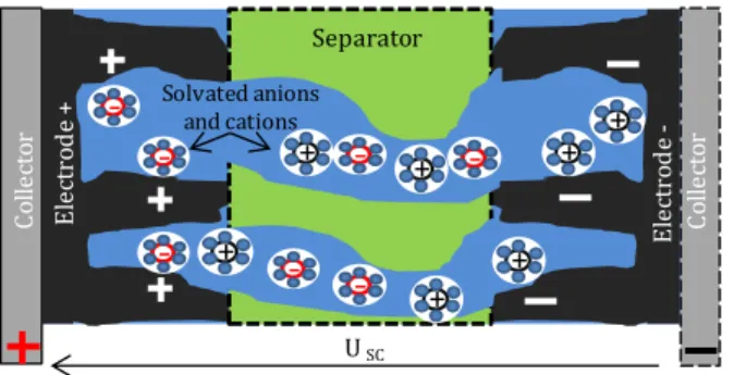
Fig. 1 is a scheme representing the different components and energy storage principle for double layer SCs. Two porous electrodes (porosity gives a bigger interface surface between electrode and electrolyte than flat electrodes) are immersed in electrolyte (a solution which contains ions and allows their displacement). The electrodes are electrically linked to the external circuit by collectors which are basically made of aluminum foils. A sheet of porous isolative material (called separator) is placed between the two electrodes to avoid electrical short circuit. Contrary to batteries, energy is not stored by electrochemical energy storage. The mechanism for-
Co lle ct or El ec tro de + USC Co lle ct or El ec tro de -Separator
-+ + + + + -+ + -Solvated anions and cationsFig. 1 Structure and energy storage for double layer SCs
-energy storage is called double layer energy storage and involves ionic and electric charges facing each other. The SCs we are studying are built with activated carbon electrode (a porous material used to maximize the contact surface between electrode and electrolyte). They use Acetonitrile (ACN) as solvent and tetraethylammonium tetrafluoroborate ET4NBF4
as ionic salt.
Activated carbon is a cheap material easy to manufacture from agriculture waste such as nutshells [12-13] and able to develop a contact surface between electrode and electrolyte (called SElectrode in equation(1)) up to 2000 m²/g [12].
ACN is the most used solvent (although it is flammable and hazardous) for SCs used in the transportation area. The physical and chemical parameters of ACN based electrolytes are indeed very interesting (high conductivity, high relative dielectric constant (εR=37) and low temperature of freezing
(around -40 °C) [6]).
The ionic salt presents the advantage to be very small (solvated cation diameter in ACN (ET4N+) is 1.30 nm and
solvated anion diameter BF4- is 1.16 nm [12]). Thus, cations
and anions are compatible with the nanometer scaled activated carbon porosity. Moreover ET4NBF4 is soluble in large
quantity in ACN.
Contrary to film capacitor, the double layer thickness (d) is not limited by a dielectric film. The solvation layer around ions plays the part of the dielectric film. Thus d is extremely thin (sub nanometer scale). Equation (1) gives the expression of the capacitance of one electrode of the SC.
R 0 Electrode dl Electrode S C d (1)
Where ε0 is the dielectric permittivity of the vacuum.
Combining the thin double layer and the high energy storage surface developed by activated carbon, SCs are able to develop capacitance up to 3000F for a mass of 0.6 kg [14]. The equivalent series resistance (ESR) of SCs is relatively small compared to batteries as there is no charge transfer implied in energy storage. The second consequence is that the double layer storage is a totally reversible mechanism and leads to a higher lifespan for supercapacitors compared to batteries. Nevertheless the amount of mass energy stored (≈ 5 Wh/kg [14]) is inferior compared to batteries.
SCs are slow ESSs compared to film capacitors [15]. As a matter of fact the interaction between the ions and pores (which are about the same size for optimization purposes) associated to solvent viscosity result in difficulty for ions to travel through the depth of porosity.
Consequently the more the frequency is low the more the ions can penetrate deep in the porosity [16] as shown in Fig. 2.
10-2 100 102 0 0.5 1 1.5 2 2.5 3 3.5 frequency (Hz) Ca pa ci ta nc e (k F)
-Pore -Pore -Pore Full capacitance Decreasing capacitance No storageSC 1 C( ) Im(Z ) 100 mHz
Fig. 2 Evolution of capacitance and ion penetration in pores with frequency of electrical signal
Thanks to the evolution of the capacitance (CSC) with
frequency, we can separate the SC ageing into three zones. In very low frequency, ions have enough time to explore the whole porosity surface. Thus, capacitance C(ω) is almost constant. Then, when the frequency is increasing, ion penetration becomes less important leading to lower effective interface surface between electrode and electrolyte ions. As a consequence, C(ω) collapses with increasing frequency. This phenomenon continues until there is no energy storage at all for higher frequencies.
B. Ageing mechanisms for SCs
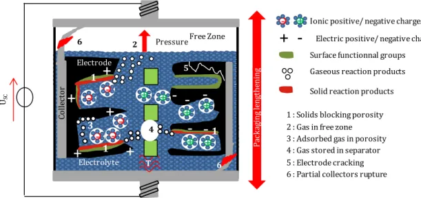
On the surface of every activated carbon electrode, there are some parasitic species [17] (called parasitic surface groups). They correspond to residues of acidic or organic chemicals used for digging porosity in pure carbon during the activation process (see Fig. 3). Contrary to carbon these chemicals are reactive under SC nominal voltage and temperature conditions. The zones where double layer is located correspond to zones where the electrical field gradient is the highest between electrode and electrolyte (as the opposite sign charges are very near from each other). Thus, the double layer zones lead to electrochemical reactions between parasitic surface groups and electrolyte [17].
The products of those reactions can be either solid or gases. Fig. 3 represents the different mechanisms associated with SCs ageing. The solids tend to accumulate in the porosity of electrodes creating a loss of energy storage surface that leads to a decrease of capacitance through time [18]. The produced gases participate to SC ageing by different mechanisms depending on the SC part where they are stored. Gases can be accumulated in the SC package in a zone free of electrolyte (we call it the free zone) leading to an increase of SC package internal pressure (zone 2). The gases can also be trapped in the porosity of electrodes by the adsorption mechanism creating a loss of usable energy storage surface (zone 3) [19] or in the separator (zone 4). The pressure increase causes electrode cracks (zone 5) and SC packaging lengthening which damages collectors (zone 6).
Thus impedance is a good parameter to monitor SC ageing as the ageing phenomena leads to a loss of capacitance (loss of energy storage surface) and an increase of resistance (decrease of the mobility of ions in the separator because of trapped gases and contacts damages with overpressure)
+
+
+
+
+
Free Zone+
6 6 Electrolyte Pa ck ag in g le ng th en in g T 4 1--
-USCSolid reaction products Surface functionnal groups Gaseous reaction products
-
+
+ -
Electric positive/ negative charges Ionic positive/ negative charges1 : Solids blocking porosity 2 : Gas in free zone 3 : Adsorbed gas in porosity 4 : Gas stored in separator 5 : Electrode cracking 6 : Partial collectors rupture
Electrode Co lle ct or
-5 -Pressure 2 1-+
+
+
+
+
1 1 3Fig. 3 Causes and impacts of SC ageing and energy storage with double layer effect
III. EXPERIMENTAL PROTOCOL
For the test we use SCs coming from three manufacturers (A, B, C) to have a representative sample of commercial high capacitance (3000 F), ACN/TEABF4 built SCs (see Table 1).
Thanks to their high mass power (ESR < 0.29 mΩ) these elements are suitable for integration in HEVs. They are nevertheless limited in term of mass energy because of ACN voltage limit.
Fig. 4 shows the principle of the test bench used for the ageing tests involving ripple current. The floating constraints are applied thanks to DC voltage sources (protected from the ripple current by 30 mH coils). The temperature is applied thanks to thermal oven. Then the SCs are stacked and connected to a programmable alternative current source (Kikusui PBZ 20-20). The alternative current (IAC) is then
applied during the whole ageing test (except during impedance spectroscopy characterizations). The temperatures of SCs packages are recorded thanks to thermocouples.
Table 2 presents the experimental plan. In a first time, three components of each manufacturer are aged with only 2.8 V, 60 °C floating constraints. In a second time sinusoidal ripple currents are added to the floating constraints on two SCs by manufacturer. The acceleration factor of ageing rate related to ripple current can be observed that way.
Two particular frequencies are investigated. The 10 kHz frequency corresponds to the order of magnitude of commutation of the power electronics converter present in vehicle power network or domestic network. The second studied frequency (100 Hz) represents a low frequency ripple that can be found in domestic applications. As the presented SCs are designed for around 120 ARMS current use and as the
maximum ripple induced by static converters is assumed equal to 10% of the total current, the ripple current for one component will be fixed to 12 ARMS.
Table 1 Electric characteristics of different manufacturer acetonitrile/ active carbon commercial 3000 F SC
Electrode Activated Carbon Electrolyte Acetonitrile Capacitance 3000 F Manufacturer A, B, C Equivalent Series Resistance ESR (mΩ) 0.20< ESR< 0.29
Nominal voltage UN (V) 2.7< UN< 2.8
Nominal Continuous current IN (ARMS) ≈120
Limit impulse current <1s (A) ≈2000 Max operating temperature Tmax (°C) 60<Tmax< 65
Cell Weigth M (g) 510<M<650 Mass energy WM (kJ/kg) 17.8< WM<21.5
Peak mass power PM<1s (kW/kg) 8.60< PM< 10.6
Fab. A SC-1 IAC=12ARMS , f L1 2.8V DC IAC IAC L6 2.8V DC Fab. C SC-6 IAC T = 60 C SC
+
-Thermocouple
Fig. 4 Scheme of the experimental test bench
Table 2 Number of tested elements per manufacturer for each ageing test Floating constraints 2.8 V 60 °C Ripple current 0 ARMS 12 A100 Hz RMS, 12 A10 kHz RMS, Man. A 3 2 2 Man. B 3 2 2 Man. C 3 2 2
IV. EXPERIMENTAL RESULTS
The capacitance and the resistance of the SCs are calculated for each impedance characterization at 100 mHz (because for frequencies equal or inferior to 100 mHz the maximum capacitance of SCs is almost reached (see Fig. 2) indicating that ions have enough time to reach all the accessible storage surface). The 100 mHz capacitance C100mHz
is calculated with equation (2) for a 100 mHz frequency and represents the energy stored in Low Frequency (LF). The 100 mHz resistance (R100mHz) represents the cumulative effect
of connections, conduction and porosity on current circulation and is calculated with (3) for a 100 mHz frequency.
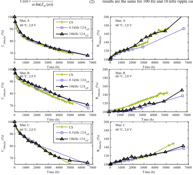
1 ( ) .Im( SC( )) C Z (2) ( ) Re( SC( )) R Z (3) Fig. 5 presents the evolution of C100mHz and R100mHz as a
function of the ageing time (averaged results by test).
The duration for the ageing tests is up to 6600 h (corresponding to 9 months) and leads to a capacitance decrease around 30%. Thus, our results are very representative of the SCs lifetime (industrials recommend to not go further than -20% for capacitance decrease). The impact of ripple current on SCs ageing is not visible on C100mHz and on R100mHz
parameters as the evolution of those parameters do not clearly differ from the (2.8V, 60°C) floating ageing results. The frequency seems not to be an ageing acceleration factor as the results are the same for 100 Hz and 10 kHz ripple currents.
0 1000 2000 3000 4000 5000 6000 7000 70 80 90 100 T ime (h) C 10 0m H z ( % ) CS 0.1kHz 12Aeff 10kHz 12Aeff 0 1000 2000 3000 4000 5000 6000 7000 100 120 140 160 180 200 T ime (h) R 10 0m H z ( % ) 0 1000 2000 3000 4000 5000 6000 7000 100 120 140 160 180 200 T ime (h) R 10 0m H z ( % ) 0 1000 2000 3000 4000 5000 6000 7000 70 80 90 100 T ime (h) C 10 0m H z ( % ) CS 0.1kHz 12Aeff 10kHz 12Aeff 0 1000 2000 3000 4000 5000 6000 7000 70 80 90 100 T ime (h) C 10 0m H z ( % ) CS 0.1kHz 12Aeff 10kHz 12Aeff 0 1000 2000 3000 4000 5000 6000 7000 100 120 140 160 180 200 T ime (h) R 10 0m H z ( % ) 60 C, 2,8 V 60 C, 2,8 V 60 C, 2,8 V 60 C, 2,8 V 60 C, 2,8 V 60 C, 2,8 V Man. A Man. A Man. B Man. B Man. C Man. C
0 1000 2000 3000 4000 5000 6000 7000 60 65 70 T ime (h) T em pe ra tu re ( °C ) Man. A Man. B Man. C 0 1000 2000 3000 4000 5000 6000 7000 60 65 70 T ime (h) T em pe ra tu re ( °C ) Man. A Man. B Man. C 2,8 V , 60 C, 10 kHz 2,8 V , 60 C, 100 Hz
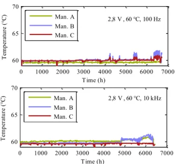
Fig. 6 Evolution of temperature for 100 Hz and 10 kHz ripple current
Fig. 6 presents the impact of ripple current on the temperature of SCs package. The tested components are designed for a 15 °C self-heating when a 130 ARMS current
passes through [14]. As self-heating is related to the square of RMS current value, any important self heating cannot be associated with the imposed ripple current. Important self heating could be the marker, for example, of exothermic electrochemical reaction related to SCs ageing.
For 100 Hz and 10 kHz ripple currents, only a slight increase of temperature (<1.5 °C) can be observed for manufacturer A and B (after 6500 h for 100 Hz and after 5000 h for 10 kHz). This slight increase accompanies the change of slope for the SC R100mHz parameter during 10 kHz
floating ageing (see Fig. 5) possibly indicating an effect of overageing on connections (at this stage the SCs are in extreme capacitance loss state). This negligible rise of temperature is a confirmation of the results presented in Fig. 5 which show that the HF ripple currents are not a factor causing ageing acceleration for SCs.
An interpretation is given in Fig. 7. As told in part II.A, SCs are low frequency ESSs. At the ageing test frequencies (100 Hz and 10 kHz) we can suppose that ions are not fast enough to enter in porosity (as the capacitance is very weak at 100 mHz and null at 10 kHz) and create high electric field gradient between parasitic surface group and electrolyte (which results in porosity blocking by reaction solids produced (see part II.B)). Thus, no zone of supplementary ageing is brought by the 100Hz and 10 kHz ripple currents.
10-2 100 102 104 0 0.5 1 1.5 2 2.5 3 3.5 frequency (Hz) C ap ac ita nc e (k F)
Full capacitance Decreasing
capacitance No storage HF ripple Zone
-Pore -Pore -PoreSurface parasitic group Solid reaction products Fig. 7 Ageing zones as a function of ion penetration and frequency
V. CONCLUSION
This paper deals about the effect of ripple current for frequencies corresponding to power electronics converters in embedded and stationary applications.
Firstly, the principle of SCs energy storage and ageing mechanisms are presented. Ageing mechanisms are related to the formation of a solid layer slowly blocking porosity and to gas production which makes the ESR of the component increase.
21 SCs coming from 3 different manufacturers are aged during 9 months with and without ripple current. Two frequencies (100 Hz and 10 kHz) are investigated. The evolution of the electric parameters of SCs (C100mHz and
R100mHz) is recorded by using impedance spectroscopy. The
temperature of SCs is also monitored while ageing. The tests reveal that the tested ripple currents do not have any significant effect on SCs ageing.
These conclusions have a great interest for integrators of SCs as they don’t have to use low pass filters to protect SCs from static converters current ripples.
VI. ACKNOWLDGEMENT
French national research agency (ANR) is supporting these research works which are part of the Supercal project. Supercal is a project held by IMS Bordeaux which combines three academic laboratories (Ampère (Lyon), IMS (Bordeaux), French institute of sciences and technology for transport, development and networks (IFSTTAR)) and manufacturers from transportation and energy storage devices sectors (Blue Solutions, PSA Peugeot Citroën, Valeo).
VII. BIBLIOGRAPHY
[1] R. German, O. Briat, A. Sari, P. Venet, M. Ayadi, Y. Zitouni, and J. M. Vinassa, “Impact of high frequency current ripple on supercapacitors ageing through floating ageing tests”, Microelectron. Reliab., vol. 53, no. 9–11, pp. 1643–1647, Sep. 2013.
[2] M. Ayadi, O. Briat, R. Lallemand, G. Coquery, and J.-M. Vinassa, “Influence of thermal cycling on supercapacitor performance fading during ageing test at constant voltage”, presented at the IEEE 23rd International
Symposium on Industrial Electronics (ISIE), Istanbul, Turkey, 2014, pp. 1823– 1828.
[3] R. German, A. Sari, P. Venet, Y. Zitouni, O. Briat, and J.-M. Vinassa, “Ageing law for supercapacitors floating ageing”, presented at the IEEE 23rd International Symposium on Industrial Electronics (ISIE), Istanbul, Turkey, 2014, pp. 1773–1777.
[4] H. K. P. Khant, K. Yamakita, K. Matsui, and M. Hasegawa, “Various voltage equalizers for EDLCs using CW circuit”, presented at the 22nd Industrial Symposium on Industrial Electronics (ISIE), Taipei, Taiwan, 2013, pp. 1–6.
[5] A. Eddahech, O. Briat, M. Ayadi, and J.-M. Vinassa, “Ultracapacitor performance determination using dynamic model parameter identification”, presented at the IEEE 22nd International Symposium on Industrial Electronics (ISIE), Taipei, Taiwan, 2013, pp. 1–5.
[6] M. technologies, Product Guide Maxwell Technologies BOOSTCAP Ultracapacitors. 2009.
[7] H. Shibuya and K. Kondo, “Designing Methods of Capacitance and Control System for a Diesel Engine and EDLC Hybrid Powered Railway Traction System”, Ind. Electron. IEEE Trans. On, vol. 58, no. 9, pp. 4232 – 4240, Sep. 2011.
[8] H. Al-Sheikh, O. Bennouna, G. Hoblos, and N. Moubayed, “Modeling, design and fault analysis of bidirectional DC-DC converter for hybrid electric vehicles”, presented at the 23rd Industrial Symposium on Industrial Electronics (ISIE), Istanbul, Turkey, 2014, pp. 1689–1695.
[9] A. Lahyani, P. Venet, A. Guermazi, and A. Troudi, “Battery/Supercapacitors Combination in Uninterruptible Power Supply (UPS)”, Power Electron. IEEE Trans. On, vol. 28, no. 4, pp. 1509–1522, 2013. [10] C. Ozkurt, F. Camci, B. Esat, and O. Toker, “Cost benefit analysis of individual cell control in batteries for Electric Vehicles”, presented at the 23rd Industrial Symposium on Industrial Electronics (ISIE), Istanbul, Turkey, 2014, pp. 1800–1804.
[11] J. P. Torreglosa, P. Garcia, L. M. Fernandez, and F. Jurado, “Predictive Control for the Energy Management of a Fuel-Cell-Battery-Supercapacitor Tramway”, IEEE Trans. Ind. Inform., vol. 10, no. 1, pp. 276–285, Feb. 2014. [12] J. Gamby, P. L. Taberna, P. Simon, J. F. Fauvarque, and M. Chesneau, “Studies and characterisations of various activated carbons used for carbon/carbon supercapacitors”, J. Power Sources, vol. 101, no. 1, pp. 109 – 116, 2001.
[13] C. A. Toles, W. E. Marshall, and M. M. Johns, “Surface functional groups on acid-activated nutshell carbons”, Carbon, vol. 37, no. 8, pp. 1207 – 1214, 1999.
[14] Maxwell technology, K2 series ultracapacitors datasheet, Document number: 1015370.3,. .
[15] M. Makdessi, A. Sari, P. Venet, P. Bevilacqua, and C. Joubert, “Accelerated Ageing of Metallized Film Capacitors under High Ripple Currents Combined with a DC Voltage”, IEEE Trans. Power Electron., pp. 1–1, 2014.
[16] R. D. Levie, “Electrochemical response of porous and rough electrodes, Advances in electrochemistry and Electrochemical Engineering”, Wiley Intersci., vol. 6, pp. 329–397, 1967.
[17] P. Azais, L. Duclaux, P. Florian, and D. Massiot, “Causes of supercapacitors ageing in organic electrolyte”, J. Power Sources, vol. 171, pp. 1046–1053, 2007.
[18] R. German, A. Sari, P. Venet, M. Ayadi, O. Briat, and J. M. Vinassa, “Prediction of supercapacitors floating ageing with surface electrode interface based ageing law”, Microelectron. Reliab., Aug. 2014.
[19] R. Chaari, O. Briat, and J.-M. Vinassa, “Capacitance recovery analysis and modelling of supercapacitors during cycling ageing tests”, Energy Convers. Manag., vol. 82, pp. 37–45, Jun. 2014.