in elastic anisotropic rock
Nam-Hung TRAN
1, Duc-Phi DO
2, Dashnor HOXHA
31Université d’Orléans, Laboratoire PRISME, 8 Rue Léonard de Vinci - 45072 Orléans, mail : nam-hung.tran@etu.univ-orleans.fr
2
Université d’Orléans, Laboratoire PRISME, 8 Rue Léonard de Vinci - 45072 Orléans, mail : duc-phi.do@univ-orleans.fr
3Université d’Orléans, Laboratoire PRISME, 8 Rue Léonard de Vinci - 45072 Orléans, mail : dashnor.hoxha@univ-orleans.fr
ABSTRACT. Based on complex variable method and on the method of conformal mapping, closed-form hydro-mechanical solution for stresses and displacements around deep tunnel is developed. The Lekhnitskii complex potential approach of anisotropic elasticity is used to include the hydraulic effect. In order to validate the solution the results of analytical solution for a tunnel opening are compared with those obtained with a numerical analysis performed with FEM code ASTER. Using this analytical solution, the anisotropic effect of linear poro-elastic behaviour to the distribution of stresses and displacements around a deep tunnel will be detailed The analytical solution would be useful for tunnel design thanks to its quick evaluation of the stress and displacement fields in linear elastic poro-media..
KEYWORDS: tunnel, closed-form solution, hydro-mechanical, anisotropic elastic, complex variable.
RESUME. En basant sur la méthode variable complexe et sur la méthode de conformal mapping, une solution analytique hydro-mécanique pour les contraintes et les déplacements autour d’un tunnel profond est développée. L’approche de potentiel complexe de Lekhnitskii pour l’élasticité anisotrope est utilisée pour inclure l'effet hydraulique. Afin de valider la solution, les résultats de solution analytique pour une ouverture circulaire sont comparés à ceux obtenus en utilisant une analyse numérique réalisée avec code MEF- ASTER. En utilisant cette solution analytique, l’effet d’anisotropie du comportement poro-élastique sur la répartition des contraintes et des déplacements autour d'un tunnel profond sera détaillé. La solution analytique serait utile pour la conception du tunnel grâce à sa capacité d‘évaluer rapide des champs de contrainte et de déplacement dans milieux poro-élastiques linéaires.
MOTS-CLÉS: tunnel, solution analytique, hydro-méchanique, élasticité anisotrope, variable complexe. 1. Introduction
The determination of stresses and displacements around a deep tunnel as well as those in nuclear waste storage, in the mining industry or traffic undergrounds, is an interesting topic in the design and evaluation of stability and safety. The analysis of rock stresses and displacement due to tunnel construction is often made with the assumption of homogeneous and isotropic rock. The tunnels, however, may be built in formations where the properties of the rock are usual not isotropic because of the orientation of minerals and discontinuities in the media. Common examples on underground construction include sedimentary and metamorphic foliated rocks. Many research results indicate that, stresses and deformations in the rock differ from those obtained in assuming isotropic properties of materials and strongly depend on the orientation of bedding or foliation with the tunnel axis [HOE 1999], [TON 2002].
A considerable amount of work on hydro-mechanical problems in isotropic medium can be found in the literature as in [CAR 1982, 1983], [DET 1997], [TOR 2009], [ABO 1998], and [CHE 2015], just to mentioned a few. In contrast, relatively little works could be mentioned when anisotropic hydro-mechanical modeling are considered. In many cases the anisotropic behavior is limited to mechanical responses of the rock around the tunnel, [EXA 2002], [KOL 2012], [HUY 2015], or below the water table [FER 1994], [BOB 2007, 2009, 2011], [NAM 2006], [CAR 2009].
The present paper devotes to study the behavior of the surrounding medium of the tunnel excavated in anisotropic rock masses accounting for anisotropic hydro-mechanical responses and in the steady-state condition. This work can be considered as an extension of the contribution of Torres [TOR 2009] which was limited in isotropic behavior case of the poro-elastic medium. For this purpose, a closed-form solution based on the complex potential approach was used to analyze the displacement and stress around the deep circular tunnel which is excavated in a transversely saturated rock. For the sake of clarity, we note that this solution is obtained in plane strain conditions with the axis of the tunnel in the plane of isotropy.
2. Problem description
Let us consider a deep tunnel with circular cross section of radius r0 excavated in an infinite transverse
isotropic poro-elastic medium. Otherwise, the medium is saturated with an initial pore pressure pff. The excavation will induce a redistribution of pore pressure, stress and displacement around the tunnel. However, we limit our study here at a long period of time when the fluid flows toward the opening and attaints the steady state with a pore pressure p0 on the wall of the borehole. More precisely, we interest in this work, the influence of the pore pressure’s variation (in “steady state” conditions) on the redistribution of stress and displacement of the surrounding medium of tunnel. This means that the study conducted here is a unilateral coupled hydro-mechanical problem when only the impact of the hydraulic solution on the hydro-mechanical response is accounted for. In comparison with other contributions (for example [TOR 2009]), this work can be considered as an extension in case of the transversely isotropic behavior of poro-elastic media (note also that the liner of tunnel is not explicitly taken into account here).
The figure 1a is a schematic presentation of the considered problem when the tunnel is subjected, at far-field, to the stresses ff, ff, ff, ff
v v h h
while the pore pressure is p0 on its wall and pff at infinity. The symmetric axis of transversely anisotropic rock coincides with the vertical axis. Thus to summarize, the following assumptions are accepted here: (1) the problem is considered in 2D plane strain condition which corresponds to the anisotropic plane (x-y plane) of the transversely anisotropic rock mass; (2) the cross section of the tunnel is circular; (3) the tunnel is deep and so far-field stresses can be assumed as homogeneous, anisotropic and gravity loading is not accounted for; (4) the steady state is considered for the fluid flow
Figure 1: Deep tunnel in transversely anisotropic rock
Below mathematical details are described hereunder for the unilateral coupled hydro-mechanical used in this work. For fluid flow in the porous medium, by combining the Darcy law and the conservation equation one obtains the following equation for the steady state and 2D plane strain problem:
2 2 2 2 0 x y p p k k x y [ 1 ]
where kx, ky are hydraulic conductivities in x-direction and y-direction respectively while p is pore pressure. The influence of the hydraulic solution on the mechanical response can be expressed through the notion of effective stress by using the Biot principle:
'ij ij b pij
[ 2 ]
where ij',ij are respectively the effective and total stress tensors.
The mechanical behavior is then completed by taking into account the equilibrium equation:
( ij) 0
Div [ 3 ]
as well as the Hooke law which represents the stress and strain relationship:
ij Sijkl kl S b pijkl kl
[ 4 ]
3. Solution Method
In order to solve the problem as described in section 1, we decompose it into two problems: problem I is purely mechanical problem in which the tunnel is excavated in the anisotropic elastic medium with imposed far-field stress ff, ff, ff, ff
v v h h
while in the problem II (called hydro-mechanical problem) we study the tunnel’s behavior due to the distribution of pore pressure, consequence of the fluid flow (Figure 1). Thereafter, based on the principles of superposition for elasticity, we have the complete solution.
Problem I is the well-known classical problem where the excavation is conducted in an anisotropic elastic medium. The solution of this problem has been widely discussed in the literature [HEF 1999], [BOB 2011] since the pioneered work of Lekhnitskii [LEK 1963] in which the stress and displacements around the borehole are determined analytically through the complex potentials. According Lekhnitskii approach, the stress component can be identified from the function called Airy stress function, F(x,y) which satisfies identically equilibrium equation [3]: 2 2 2 2 2 ( , ) ( , ) ( , ) ; ; x y xy F x y F x y F x y y x x y [ 5 ]
Hence, using the constitutive equations [3], the strain compatibility [5] for two-dimensional problems yields:
4 4 4 2 2 11 4 (212 33) 2 2 22 4 ( 11x 12 y) 2 ( 21x 22 y) 2 F F F p p S S S S S b S b S b S b y y x x y x [6]
where Sij are reduced compliance coefficients and bx, by are Biot coefficients in the x-y plane.
Here we summarize the approach to solve the problem, the details of the method are presented in [LEK 1963]. The problem I corresponds to case where Eq. [6] have no right-hand side. Lekhnitskii [LEK 1963] proposed a solution of Eq. [6] by introducing the complex variable zk = xy, where k (k=1, 2) are the complex roots (with positive imaginary part) of the following characteristic equation:
4 2 22 (212 33) 11 0 S S S S [7] By defining: '( ) ,( 1, 2) k k k F F z k z [8]
we obtain the general expression for the stress and displacements components as follows:
2 ' 2 ' 1 1 2 2 1 1 2 2 ' ' 1 2 1 1 2 2 ' ' 1 1 2 2 2 Re{ } 2 Re{ } 2Re{ } 2Re{ } 2 Re{ } init x x x init y y y init xy xy U p p U q q [9] where init, init, init
x y xy
are components of initial stress and the coefficients p1, p2, q1, q2 are determined by the relations: 2 2 22 22 1 11 1 12 2 11 2 12 1 12 1 2 12 2 1 2 ; ; S ; S p S S p S S q S q S [10]
and ‘Re’ stands for the real part.
To determine these potentials Lekhnitskii [LEK 1963] proposed a conformal mapping to transform the infinite domain outside the tunnel, of radius r0, in the zk planes to the infinite domain outside the unit circle in the k planes. This transformation is written as:
1 0(1 ) 0(1 ) ( ) 2 2 k k k k k k r i r i z w or 2 2 2 0 0 (1 ) (1 ) k k k k k z z r r i (k=1,2) [11]
The potentials 1( ),z1 2( )z2 to be determined can take the following form as proposed by Lekhnitskii [LEK 1963]:
1 1 2 2 2 1 1 1 1 2 1 1 2 2 1 1 1 1 ( ) (m m) n; ( ) (m m) n k k z b a z b a
[12]where the coefficients a bm, mare determined through the boundary conditions on the wall of the tunnel:
1 1 2 2 1 2
2 Re{ } n ; 2 Re{ } n
s s
X ds Y ds
[13]with Xn and Yn are forces components acting on the tunnel wall in the x, y directions. The integral sign denotes line integrals along tunnel wall circumference.
Meanwhile, problem II considers the influences of pore pressure variation on the mechanical response of the rock mass. According to this model, the distribution of the pore pressure is analyzed first and then the mechanical response of the rock due to the changes of pore pressure is computed based also on the hydraulic and hydro-mechanical complex potentials. This approach is recently detailed and discussed by Bobet and Yu [BOB 2015] when they determined the stress field near the tip of a crack in the poro-elastic transversely isotropic saturated rock. More precisely, knowing the pore pressure distribution around the crack at the steady state and hence the hydraulic potential, these authors propose the mechanical potentials owing the same form as ones of the hydraulic potential. After some development, these authors showed that the displacements as well as the stress around the crack tip can be deduced. In the present work, this approach is used and we will show that this solution is also applicable to the case of the deep tunnel with a circular cross section.
In this case the general Eq.[6] is used and solving this equation means that we have to determine a homogeneous solution corresponding to the mechanical case and a particular solution ( * * *
h p
F F F) in which the homogeneous solution is found as the previous problem I. We search now the particular solution Fp*. For this
purpose, the general solution of Eq. [1] takes the form pp x( wy) in which the constant is determined w from characteristic equation: 2
w 0
y x
k k . Denoting the complex root with the positive imaginary part by , w
the general solution of Eq. [1] for the hydraulic field may be written:
w
w2Re ''( ) 2 Re{ '( )}
ff ff
pp F z p z [14]
where F zw( w)is a complex function and (zw) Fw/zwis a potential, the prime denotes derivative with respect to
w, w w ; w x/ y
z z x y i k k . The particular solution can take the form:
* w 2Re ( ) p w F F z [15]in which the real coefficients is determined by substituting Eq. [14] into Eq.[6], as:
2 1 2 4 2 11 12 33 2 w w 2 w (2 ) S S S S [16] where 1S b11xS b12 y;2S b21xS b22 y [17]
In the steady-state condition, pore pressure can vary theoretically from the tunnel’s wall to infinite. However, at a certain distance R quite far enough from the opening wall, we could consider that the pore pressure does not change, i.e, it is restored like initial one as indicated in [TOR 2009]. Therefore, the analysis of pore pressure change can be limited in the zone around the tunnel corresponding to this distance R from its wall, and hence we interest particularly the mechanical response of the rock under the influence of fluid flow in this zone.
As pointed out by different authors [TOR 2009], [BOB 2015], the distribution of pore pressure around the tunnel with constant pressure p0 on the wall of the opening and the far-field pressure pff takes the logarithmic form:
0 Re log w log ff ff p p p p R R [18]
Owing to the fact that * * * 1( ),1 2( ),2 p(w)
F z F z F z have the same order of effect on the displacements and stresses, thus we try the following forms for stress functions * *
1( ),z1 2( )z2 : 1 * 1 0 1 1 log log 1 '( ) 2 ff p p N R R z and 2 * 2 0 2 2 log log 1 '( ) 2 ff p p N R R z [19]
where N1 and N2 are complex constants that are determined as [BOT 2015]. Stresses and displacements can be computed according the following relations:
2 * 2 * 2 * 1 1 2 2 * * * 1 1 2 2 * * * 1 2 * * * 1 1 2 2 * * * 1 1 2 2 2 Re{ ' '} 2 Re{ '} 2 Re{ } 2 Re{ } 2Re{ ' '} 2Re{ '} 2Re{ } 2 Re{ } 2Re{ ' '} 2 Re{ '} x w w x w w y w y w w xy w w U p p p U q q q [20] in which w 11 w2 12; w 12 w 22 w S p S S q S [21]
It is not difficult to see that, stress on the surface of the tunnel wall induced by the potentials
* * *
1( ),z1 2( ),z2 w(zw)
are not trivial and they are given by the following expressions:
2 2 2
w w
0 1 1 2 2 0 1 2 0 1 1 2 2
( ) Re[ ]; ( ) Re[ ]; ( ) Re[ ]
x p pff N N y p pff N N xy p pff N N
[22]
Therefore, to satisfy the conditions of zero stress on the surface of tunnel wall, we inject stress with magnitudes equal to those in [22] with opposite sign that act on the face of tunnel wall:
0 0 1 1 1 ( ) ( ) 2 2 ; ( ) 2 2 2 x y 2 y x xys 2 y x xy r cos in sin cos [23]
The potentials, stresses and displacements induced by the components in [23] are then determined according to the formula presented in [12] and [9], which gives the full solution of the problem.
4. Numerical applications and discussions
For the validation purposes, the analytical solution obtained is compared with results obtained numerically using the finite element method implemented in Code Aster. Precisely, in Code-Aster, the specified changes of pore pressure in the rock mass can be generated by activating the purely hydraulic model. When the pore pressure field reaches the steady state, one can extract the pore pressure field that will be injected in the mechanical model as a body force field. Through this procedure the distributions of stress and displacement can be determined as consequence of the pore pressure’s change. For the numerical application here, the parameters used were: the radius of the tunnel r0=1m, the mechanical properties of the transversely isotropic rock are
respectively Ex=7800 MPa, Ey=2400 MPa, xz=0.22; yx=0.02, Gxy=830 MPa, kx=10-6 m/s, ky=10-7 m/s, the
pore pressure on the tunnel’s wall and at infinite are p0=0 MPa, pff=4.5 MPa while the far-field stress is isotropic
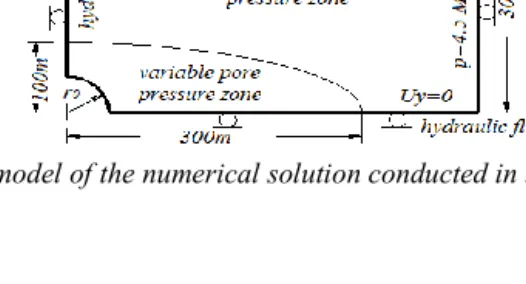
with magnitudes of -12,5 MPa. Due to the symmetric reason, in the numerical simulation only one fourth of the model was considered. In addition, because of the anisotropy of hydraulic conductivities in two directions x and y, an oval zone of hydraulic perturbation occurs around the tunnel. The dimension of the numerical model is taken equal to 300 and to 500m from the center of the circular hole while the zone where the pore pressure perturbation is limited to 100m and to 300m following the y and x directions respectively (Figure 2). Our numerical results show that these dimensions can be considered far enough in comparison with the analytical solution.
The analytical solution is firstly validated by comparing it with numerical ones. Thereafter, based on the analytical solution we discuss also the anisotropic effects on the behavior of tunnel. Particularly, in order to analyze the effect of water pressure, we study three cases where the excavation is realized respectively in: dry ground, saturated ground with uniform pore pressure and saturated ground with drainage (called here as drained case). Note that the second case corresponds to the case where the tunnel is excavated in saturated ground with a waterproof layer covering the tunnel wall (undrained case). Contrary to this case, in the third case we investigate the influence of the pore pressure attained at a long period (meaning that steady state is obtained) to the tunnel behavior. This third case, as pointed out by [TOR 2009] corresponds to the case where there exists a drain on the tunnel’s wall that collects and removes water from the ground.
Note that in all cases, the total far-field stresses are the same. Otherwise, to elucidate the anisotropic effect, the analytical results obtained in the anisotropic rock will be compared with ones in the isotropic rock in all three scenarios. For the isotropic solution case, the material properties are chosen equal to ones of the anisotropic medium following the vertical direction as mentioned in the section 3.
In Figs. 3-4 are presented the distribution of radial and ortho-radial stresses, displacement obtained from the three cases of study following the vertical cut at the center of the tunnel. In all cases we can observe that the analytical solution coincides with ones calculated from the finite element method where the maximum difference is inferior 1%. These results allow validating the closed form solution developed from the complex potential approach in case of uncoupled hydro-mechanical behavior of the tunnel in the transversely isotropic medium. In comparison with the solution obtained in the isotropic case, we can remark some differences in the solutions determined in the anisotropic rock mass, particularly in the zone near the tunnel’s wall. For example, we can observe that the hoop stresses are superior and the displacements are more significant in the anisotropic case. In addition, in the second study case, we can observe a zone with tensile radial stress which appears near the tunnel wall. It suggests that, in the case of construction a thin layer of waterproofing on the wall of tunnel, the water pore pressure could produce a tensile stress field around this layer which can contribute a significant impact to the stability to the tunnel wall (notably when the material is considered to fail plastically owing a low tensile strength). This result is consistent with the discussion of [TOR 2009] when they studied the behavior of tunnel with impermeable liner excavated in saturated ground with uniform pore pressure.
a) b) c)
a) b) c) Figure 4: Radial displacements in the a) dry ground; b) uniform pore pressure and c) drained ground
a) b) c)
Figure 5: Contour of radial stress in the case of (a) dry ground (b) uniform pore pressure and (c) drained ground
a) b) c)
Figure 6: Contour of radial displacement in the case of (a) dry ground (b) uniform pore pressure and (c) drained ground
In Figs. 5 and 6 are highlighted the contours of radial stress and radial displacement for three cases: dry ground, uniform pore pressure and saturated and drained ground. It can be seen that, a tensile zone occurs around the borehole in the case of uniform pore pressure whereas it is opposite in two rest cases (Fig 5). The figure 6 shows that the radial displacements in the two first scenarios are the same. This is because there is not redistribution of the displacements when there is no fluid flow in the medium.
a) b)
Figure 7: Ratio of the radial displacement determined in the tunnel wall following the horizontal and vertical directions with respect to the anisotropic degrees of the medium.
Then in Figure 7 are presented the influence of the anisotropic degree on the convergence of the tunnel. Concretely, we illustrate the ratio of the radial displacement determined in the tunnel wall following the horizontal and vertical directions with respect to the anisotropic degrees of the medium which are characterized by the ratio of the Young’s modulus (Ex/Ey) and of the hydraulic conductivity (Kx/Ky). As expected, the increase of Young’s modulus ratio will reduce the ratio of radial displacement (the displacement is much smaller in the direction where the stiffness is more important). The results highlight also the influence of the hydraulic properties where we can also observe that the significant increase of hydraulic anisotropy will decrease the displacement’s ratio.
5. Conclusions
In this work, a closed form solution for unilateral coupled hydro-mechanical behavior was derived and used to study the behavior of deep tunnel excavated in a transversely isotropic medium. This solution based on the complex potential approach of Lekhnitskii taking into account the distribution of pore pressure was validated by comparing with the results of numerical modeling in FEM Code ASTER. Some numerical applications were introduced to study the anisotropic effect on the tunnel behavior in different case of pore pressure distribution in the medium. These results show that the distribution of stress and displacement around the tunnel are significantly influenced by the anisotropy of the porous medium. It should be noted that the present solution seeks to determine the stress and displacement field at a long period of time corresponding to the steady-state. A more general solution in the transient state is necessary which will be an interesting subject and contributes in our perspective work.
6. Bibliography
[ABO 1998] ABOUSLEIMAN A.,CUI L., « Poroelastic solutions in transverselyisotropic media for wellbore and cylinder ». Int. J. Solids Structures, Vol. 35, Nos 34-35, pp 4905-4929
[BOT 2007] BOBET A.,NAM S., « Stresses around pressure tunnels with semipermeable liners ». Rock Mech Rock Eng, 40(3):287–315
[BOT 2011] BOBET A.,« Lined circular tunnels in elastic transversely anisotropic rock at depth ». Rock Mech Rock Eng, 44(2):149–167
[BOT 2015] BOBET A., HAITAO Y., « Stress field near the tip of a crack in a poroelastic transversely anisotropic saturated rock». Engineering Fracture Mechanics, 141 (2015) 1–18
[TOR 2009] CARRANZA TORRES C.,ZHAO J., « Analytical and numerical study of the effect of water pore pressure on the mechanical response of cylindrical lined tunnels in elastic and elasto-plastic porous media ». Int J Rock Mech Min Sci, 46(3):531–547
[CHE 1998] CHENG AH-D., « On generalized plan strain poroelasticity ». Int J Rock Mech Min Sci, 35(2):183–193
[DET 1993] DETOURNAY E., CHENG AH-D., Fundamentals of poroelasticity, In: Hudson JA (ed.) Comprehensive rock engineering: principles, practice and projects, Pergamon Press, Oxford, UK, vol 2, pp 113–171
[EXA 2002] EXADAKTYLOS GE.,STAVROPOULOU MC., « A closed-form elastic solution for stresses and displacements around tunnels ». Int J Rock Mech Min Sci, 39(7):905–916
[KOL 2012] KOLYMBAS D.,WAGNER P.,BLIOUMI A., « Cavity expansion in crossanisotropic rock ». Int J Numer Anal Methods Geomech, 36(2):128–139
[HEF 1999] HOEFY AM., LO K., « Analytical solutions for stresses and displacements around tunnels driven in cross-anisotropic rocks ». Int J Numer Anal Methods Geomech, 23(2):161–177
[HUY 2015] HUY TRAN M., SULEM J., « A Closed-Form Solution for Tunnels with Arbitrary Cross SectionExcavated in Elastic Anisotropic Ground ». Rock Mech Rock Eng, 48:277–288
[LEK 1963] LEKHNITSKII SG., Theory of elasticity of an anisotropic elastic body, Holden-Day, Inc., San Francisco
[TON 2002] TONON F.,AMADEI B., « Effect of elastic anisotropy on tunnel wall displacements behind a tunnel face». Rock Mech Rock Eng, 35(3):141–160