HAL Id: hal-01724651
https://hal.insa-toulouse.fr/hal-01724651
Submitted on 23 Mar 2018
HAL is a multi-disciplinary open access
archive for the deposit and dissemination of sci-entific research documents, whether they are pub-lished or not. The documents may come from teaching and research institutions in France or abroad, or from public or private research centers.
L’archive ouverte pluridisciplinaire HAL, est destinée au dépôt et à la diffusion de documents scientifiques de niveau recherche, publiés ou non, émanant des établissements d’enseignement et de recherche français ou étrangers, des laboratoires publics ou privés.
Basic creep of concrete under compression, tension and
bending
Narintsoa Ranaivomanana, Stéphane Multon, Anaclet Turatsinze
To cite this version:
Narintsoa Ranaivomanana, Stéphane Multon, Anaclet Turatsinze. Basic creep of concrete under compression, tension and bending. Construction and Building Materials, Elsevier, 2013, 38, pp.173-180. �10.1016/j.conbuildmat.2012.08.024�. �hal-01724651�
1
Basic creep of concrete under compression, tension and bending
Narintsoa Ranaivomanana
a, Stéphane Multon
a*, Anaclet Turatsinze
a(a)Université de Toulouse; UPS, INSA; LMDC (Laboratoire Matériaux et Durabilité des Constructions); 135,
avenue de Rangueil; F-31 077 Toulouse Cedex 04, France
Abstract
Investigations on concrete creep are often limited to the compression behavior due to the difficulty of performing tensile tests on cement-based materials. This paper describes the experimental setup developed to achieve direct tensile and bending concrete creep. The precautions taken to obtain relevant data are described. For comparison, tensile, flexural and compressive basic creep test were conducted in parallel. Although the approach is still controversial, the basic creep strain was determined by subtracting the shrinkage strain and instantaneous strain from the total strain. Results available for specimens subjected to 50% of the strength in tension or in compression are presented. The final discussion compares the basic creep under the different types of loading.
Keywords: concrete, basic creep, compression, tension, bending
2
I Introduction
Because of its poor strain capacity and low tensile strength, concrete is brittle and highly sensitive to cracking. In most cases, cracks can significantly reduce the lifetime of a structure by allowing the ingress of aggressive agents. Cracks have various origins, which are all associated with the existence of extensions: effect of external loading, physicochemical pathologies leading to the formation of new expansive products (Alkali-Aggregate Reaction – AAR, Delayed Ettringite Formation – DEF, corrosion). A non-uniform state of deformation associated with thermal or hydric gradients or restrained strain in bonded cement-based overlays induce built-in tensile stresses which can also initiate cracking. The heterogeneity of concrete also plays an important role in the mechanism of crack formation. Even if a specimen is tested in compression, the first damage that occurs at the paste-aggregate interface is the consequence of tensile stresses resulting from the differences between the two phase moduli (for paste and aggregate) and from the interfacial transition zone (ITZ) [1], which has limited mechanical performance. According to Liners [2], the application of a compressive preload on a specimen can generate damage in tension, resulting in a significant drop in the tensile strength of up to 50% depending on the level and the duration of loading application. Therefore, in order to predict the risk of cracking in concrete elements, it is important to focus on the mechanical properties of concrete in tension, and particularly on its delayed behavior, the effects of which (cracking or stress relaxation) are not yet well understood. Since Freyssinet highlighted the creep of concrete in France in 1912, regardless of Hatt’s findings in the United States in 1907 [3], the phenomenon has been extensively studied, as shown by the numerous publications on this topic (see [4-10] for example). However, due to the difficulties of performing a tensile test on cement-based materials [11], particularly for fixing of the samples to the loading device [12] and measuring the values of the strains, which are too small for most extensometers to cope with, the majority of experimental studies on concrete creep have dealt with compressive creep. When experiments involve tensile creep of cement-based materials, the tests are usually limited to early age behavior [11, 13-23]. However, as the tests are performed a short time after casting, the coupling between creep and the effects of hydration (strength gain, shrinkage, etc.) remains very noteworthy. Contributions related to the tensile creep of cement-based materials beyond 28 days after casting, corresponding to stabilized hydration reactions, are relatively rare. Such
3 studies deal, on the one hand, with the influence of various parameters (related to the material properties and / or to the test conditions) on tensile creep [24-28] and, on the other hand, with the comparison between tension and compression behavior [27, 29-32].
This paper focuses on achieving direct tensile and bending creep devices so that tensile and compressive concrete creep can be compared in the corresponding direct tests and in bending tests. The experimental setups developed are presented first. All the precautions necessary to obtain relevant measurements are described. These points are important because tensile creep strain is low and some artifacts, due to temperature change, for example, can prevent any analysis of the results. The specimens tested were protected from drying by watertight adhesive aluminum foil that maintained the conditions required for basic creep [33]. Then, experimental results concerning shrinkage and total strains are presented and analyzed. Although the approach is still controversial, the basic creep is determined by subtracting the instantaneous strain due to the loading of the specimen and the strain due to the autogenous shrinkage from the total strain. Basic creep under tension and bending is finally compared to compressive creep. The analysis of results highlights considerable coupling, more than that observed in compression, between shrinkage and tensile creep.
II Experimental program
II.1 Material
Tests were carried out on a High Performance Concrete. As previously explained, the knowledge of the viscoelastic properties in compression but, above all, in tension is essential for the design of concrete-based structures if cracking risks are to be reduced to a minimum. The formulation of the concrete, given in Table 1, was developed by ANDRA (French Agency for Nuclear Waste Management) for nuclear waste repository structures in deep geologic formations. This concrete mix has already been studied extensively through investigations concerning instantaneous and delayed mechanical behavior in compression [34-36].
The average density of the fresh concrete was 2410 kg/m3 and the required fluidity, characterized by a slump value of 21 cm, was obtained by adding a superplasticizer based on modified polycarboxylic ether. Depending on the type of tests to be performed and on the number of samples required, several specimens were cast for:
4 - compressive creep, carried out on cylindrical specimens (110 mm in diameter and 220 mm in height) with a space reserved in the center to house displacement transducers.
- tensile creep, measured on 70×70×280 mm prisms. - bending creep, measured on 100×100×500 mm prisms.
The average compressive strength and Young's modulus of this HPC, measured from quasi-static tests on six different batches, were respectively 69.7 MPa and 41925 MPa with a dispersion of less than 5% for the six batches. The mean direct tensile strength, measured at 28 days on 10 specimens, was 3.0 MPa with a coefficient of variation of 15%. In order to reduce uncertainty, the specimens used to determine the basic mechanical properties and the ones used for creep tests were from the same batch. Direct tensile strength measurements showed larger dispersions than those of compressive strength. This can be explained by the effect of the usual heterogeneity of concrete, which has more influence on tensile properties than on compressive ones. Whereas a compressive stress tends to consolidate concrete (by closing the pre-existing microcracks and reducing the initial porosity), tensile stress tends to induce local damage of the material microstructure by propagating initial defects (shrinkage induced cracking, air bubbles, etc.). Therefore, the response in tension becomes more sensitive to initial defects, the concentration of which is closely related to the concrete heterogeneity. During creep tests, the loading rate (which is the ratio between the applied stress and the concrete strength) is an important parameter for creep strain analysis and interpretation. So, accurate knowledge of the concrete strength prior to the creep loading is an important issue. Unfortunately, such a goal is not easy to achieve in the absence of non-destructive tests to determine the concrete strength. Because of the scatter on the tensile strengths, a loading rate based on the average strength of the concrete leads to creep test results that are somewhat biased, especially in cases of high stress level [28].
After demolding, the specimens used for creep tests were first stored in water for 15 days to limit capillary depression effects by saturating the porosity. In order to dissociate creep from the drying effects (shrinkage, cracking, etc.), tests were performed in autogenous conditions (without moisture exchanges with the environment) after the first curing in water. For this purpose, the specimens were first dried and then sealed with triple layers of self-adhesive aluminum foil [33]. The first drying was performed during about 12 hours in order to avoid the phenomenon of capillary rise which could prevent the good bonding of the aluminum foil
5 and of the strain gauges and thus to maintain constant conditions during the test period. The weight loss during this superficial drying was about 0.05% of the specimen weight. They were then equipped with extensometers for strain measurement and were stored in the test room where temperature and humidity were controlled (20°C ±1°C, 50% RH ±5%) until the creep tests at 28 days. This curing procedure provided an additional advantage for the present study in that the development of hydration could be considered as relatively stable before the start of the creep tests
II.2 Experimental devices
• Compressive creep test apparatus
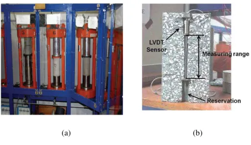
The compressive creep devices were equipped with hydraulic jacks. The device allowed simultaneous loading of 2 aligned specimens (Figure 1-a).
Longitudinal deformations were recorded by means of inductive transducers located within a reservation created during casting by placing a removable metallic insert on the mold axis (Figure 1-b). The sensor (stroke ± 0.5 mm) measured the relative displacement of two sections separated by 115 mm and located outside the hooped area. The measurement was made thanks to a LVDT sensor for which the extended base of measure is arranged along the central axis of the specimen at the time of casting the concrete: the central steel rod was, in this case, fixed to the lower part of the specimen by a steel nut embedded in the concrete during casting. The LVDT sensor was fixed to the upper part of the specimen. Thus, the displacement of the magnetic core of the steel rod corresponds to the displacement between the nut and the LVDT sensor. The deformation of the specimen core is thus obtained by dividing the displacement by the measurement basis (115 mm). Previous studies had shown that the strain measurement uncertainty was equal to 9 µm/m and that the difference from an external measurement (on three generatrices on the surface of the specimen) was negligible (less than 5%) [37]. The loading and strain measurements were performed in accordance with the RILEM recommendations [38].
• Tensile creep test apparatus
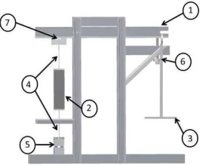
For the purposes of the study, an oedometric device used in soil mechanics was transformed to measure tensile creep (Figure 2). The tensile creep test apparatus was a rigid frame with a hinged lever arm ( in Figure 2). The 5/1 ratio of the lever arm allowed high loading levels
6 to be reached while manipulating masses of reasonable weight. A 70×70×280 mm prismatic specimen ( in Figure 2) was loaded using calibrated weights placed on a plate ( in Figure 2) fixed to the lever arm. The force was then transmitted to the specimen through a cable, one end of which was welded to a steel cap glued on to one side of the specimen while the other end was hinged to the frame ( in Figure 2). A screw system located at the bottom of the bench ( in Figure 2) allowed the horizontality of the lever arm to be controlled and thus the 5/1 ratio to be kept during the loading. A stop placed below the lever arm ( in Figure 2) prevented any sudden fall of the weights in case of rupture of the loaded specimen, thus reducing the risk of accident.
Creep strains generally develop very slowly. In the case of tensile creep, given the Young’s modulus and the loading rate calculated with respect to the tensile strength, the strains were very small. In such conditions, a thermal length change can prohibit any useful analysis of the results. For this reason, all the experiments were performed in a test room where temperature and RH were controlled. Additional precautions were taken during the test: two specimens, one loaded to measure tensile creep and the other unloaded to measure shrinkage strain, were positioned side by side in a thermally insulated box (Figure 3) and were thus maintained in the same thermo-hygrometric conditions.
One of the major difficulties when performing a tensile test on cement-based materials concerns the fixing of the specimen to the loading device. Devices commonly used on other materials, such as steel grips or clamps, are inappropriate for a brittle material like concrete. During tensile tests, concrete specimens have commonly been attached by [39]: anchoring a metallic insert in the concrete [28, 40], gluing samples [30-32], lateral grips [19, 41], or using specimens shaped like dog bones [24, 25, 29]. Each of these methods has its associated drawbacks, such as stress concentration in areas of change in section, difficulty in obtaining perfect alignment of the load direction with the axis of the specimen, and generation of a non-uniform stress field in the specimen [39]. In this study, the solution of gluing specimens with methacrylate adhesive was used. There are several advantages to this technique, such as rapid hardening (approximately 15 minutes) and high tensile strength (approximately 20 MPa [30]). The top and bottom of the specimen were unpacked and dried superficially before the glue was applied because good adhesion could not be achieved in the presence of moisture. They were then sandpapered and cleaned with compressed air in order to remove laitance, dust etc. The necessary condition for a tensile stress state to be achieved is the alignment of the load
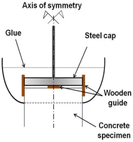
7 direction with the axis of the specimen. For this purpose, steel caps, of the same size as the specimen and connected to a flexible cable, were manufactured. The contact between the cable and the loading frame was achieved through a cylindrical roller ( in Figure 2) welded to the end of the cable, which was set at a specific location of the lever arm, thus behaving as a hinge. Frictional phenomena occurring at this joint were prevented as far as possible by using thick grease. In addition, the use of flexible cable instead of rigid attachments significantly reduced additional bending effects in the specimen. As the caps remained completely immersed in the glue, it was difficult to position them in such a way as to achieve perfect alignment. For this purpose, small wooden guides were fixed to the sides of the specimens and between the specimen and the cap, as indicated in Figure 4, before glue was applied. The efficiency of the bonding system was verified during the loading of the specimens by the quasi-symmetry of the instantaneous strains measured on two opposite sides. This symmetry indicated the absence of flexural moment in the system formed by the loading device and the specimen.
Finally, long-service-life strain gauges were used for long-term monitoring. The gauge length was 60 mm and the stainless steel metallic support resisted temperature and capillary rise. Special glue, insensitive to capillary rise, provided a good, durable bond between the specimen and the strain gauges. The gauges were connected to a strain indicator and data-recorder via a quarter-bridge arrangement and strain values were recorded regularly.
• Flexural creep test apparatus
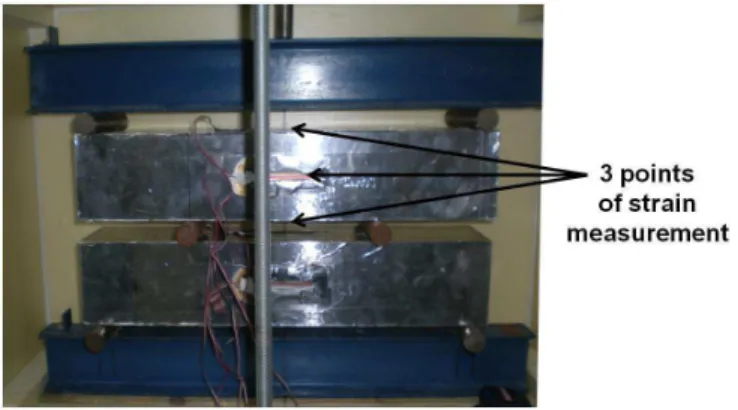
The principle of the flexural creep device (Figure 5) was the same as for the oedometric device used in soil mechanics. In this case, the soil specimen was replaced by a concrete beam. The load was applied, as in the case of tension, by means of calibrated weights placed on a plate ( in Figure 5) fixed to a 5/1 ratio hinged lever arm ( in Figure 5). Through a steel I-beam associated with two metal rollers acting as simple supports ( in Figure 5), a rigid frame linked to the lever arm leant on a 100×100×500 mm prismatic concrete specimen. The specimen was thus in a four-point bending configuration with a span of 460 mm between the lower supports and 175 mm between the upper supports (Figure 6). The distance of 175 mm corresponding to the area of constant bending moment had been chosen so that there was enough space to allow the strain gauge to be attached considering the Saint-Venant principle in usual beam theory. However, this distance between the loading points could not be too large as we needed to minimize the weights necessary to obtain the focused stress
8 level. Two specimens were tested simultaneously (Figure 6). Creep and shrinkage specimens were also placed in a thermally insulated box ( in Figure 5) in order to absorb the effects of temperature variation if necessary.
In the bending test, the concrete creep causes deflection but it should not be forgotten that, if the creep is different in tension and in compression, a displacement of the neutral axis is also unavoidable. Thus for a complete series of tests, each specimen was fitted with three strain gauges: one each on the upper and lower sides of the beam and a third one on the initial neutral axis (Figure 6). These three strain measurements provided sufficient data to calculate the deflection and the displacement of the neutral axis and to check whether the cross-section remained plane during creep tests. The strain monitoring system used for the bending test was similar to the one used for monitoring the tensile creep strains.
III Measurements
III.1 Shrinkage
Even unloaded, concrete undergoes a continuous variation in size, usually a contraction called shrinkage, the origins of which can be physical (thermal, hydric) or chemical (hydration effects). But, as was mentioned above, there may also be swelling, caused by certain diseases of the concrete, or expansion, especially in case of temperature increase. In this study, only autogenous shrinkage was considered and, in order to minimize its effect on creep, tests were performed 28 days after casting. It is worth mentioning again that tensile creep strains were expected to be small [30-32] and probably of the same order of magnitude as shrinkage strains. In order to acquire good data on the shrinkage capacity of the specimens studied, it was necessary to associate a control specimen with each loaded specimen. The control specimens were the same shape and size and cast in the same batch in order to minimize scatter. Measurements on stress-free specimens led to interesting conclusions on the scatter of shrinkage measurements. Swelling can be observed on concrete specimen just after sealing [42]. In this study, the specimens were sealed 15 days before the creep loading test in order to prepare the specimens for creep tests and obtain homogeneous moisture conditions in the specimens. All the strain measurements began at this time and thus only shrinkage was observed. The results indicated little dispersion between the strain values obtained on two opposite sides of the same specimen, the difference observed on prismatic specimens remaining less than 4 µm/m. Concerning the comparison of shrinkage between two specimens
9 of the same batch, the maximum difference observed was 2 µm/m. Considering the accuracy of the measurements, these low values confirm that autogenous shrinkage was uniform within the specimen and the batch. This ability to access the shrinkage strains accurately was important for studying concrete basic creep. Figure 7 shows the shrinkage measured from 28 days for specimens of two different sizes (70 x 70 x 280 mm prisms and 100 x 100 x 500 mm prisms) kept in the insulated box or directly in the air-conditioned room. The specimens kept in the insulated box showed shrinkage strains lower than 20 µm/m after 80 days. The primary aim of the shrinkage measurements performed outside the insulated box was to compare the shrinkage measurements made with a gauge against results available from previous measurements performed with an extensometer on a specimen based on the same concrete mix. The comparison with Ladaoui’s results [35] highlights fairly good agreement but strain gauge measurements show better precision than extensometer measurements. The second conclusion from this measurement pointed out the impact of the specimen storage conditions on the shrinkage strains. It was verified that the use of three aluminum layers prevented mass losses (no mass variation was detected during the first 100 days). However, although mass losses were not detected (measurement resolution of 1 g), better autogenous conservation was obtained in the insulated box. This shows a second advantage of using such boxes to control shrinkage conditions.
III.2 Instantaneous strains
The loading was applied quasi-instantaneously to avoid undesirable dynamic effects [43]. The difference between the instantaneous strains measured on two opposite sides of the specimens used for tensile creep was limited (35 µm/m vs 36 µm/m and 32 µm/m vs 37 µm/m respectively on the first and the second specimens loaded at 50% of the tensile strength). Concerning the bending, the strains measured on the extreme fibers, in tension and in compression, were similar (36 µm/m vs -34 µm/m and 33 µm/m vs -31 µm/m respectively on the first and the second specimens loaded at 50% of the tensile strength). This shows the good symmetry of the loading with the bending creep device.
The Young’s modulus of the concrete was calculated from the applied stress and the measured instantaneous strain for the three types of creep test: 41215 MPa in tension, 44570 MPa in compression and 44065 MPa for the flexural test. These values were not significantly different from the Young’s modulus obtained during a conventional test to characterize the material strength [44]: 41925 MPa. Despite the scatter on the measurements
10 (due to the degree of repeatability, concrete heterogeneity, etc.), the difference between the various experimental moduli appears to be small for the three types of loading.
III.3 Total strains
The results presented in this paper correspond to a loading level of 50% of the compressive or tensile strengths. Actually, it was difficult to obtain precise values of stress levels, especially in the case of tension, because of the large dispersion of tensile strengths (10 to 20% for specimens of the same batch). In addition, the application of a sustained load could also modify the material microstructure in compression [8] as in tension [26], thus affecting the strength value. Therefore, the applied loading rate could change during a creep test but this variation was difficult to quantify precisely because of our lack of knowledge on the phenomena involved.
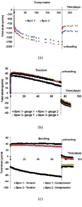
The strains measured in the creep tests in compression, in direct tension and in four points bending on specimens from the same concrete batch have been plotted in Figure 8. The results reported correspond to the raw data obtained during the creep test in compression (Figure 8-a), in direct tension (Figure 8-b) and in four point bending (Figure 8-c). The sign convention used is that tensile strains (extensions) are considered positive and compressive strains (contractions) negative.
During the first days of loading, increasing strains were observed regardless of the type of loading. These observations are in agreement with the theory associating short-term basic creep with a micro-diffusion of water under stress. Differences in behavior occurred after about five days:
- For compressive loading, the strain kinetics was initially very fast and decreased gradually. It remained significant even after 200 days of loading (Figure 8-a).
- In the case of direct tension, strains tended to decrease (Figure 8-b). This point will be discussed below.
- For bending tests, the strain in flexurally induced compression showed a trend similar to the one observed in direct compression (Figure 8-c). The total strains measured on the stretched fibers of specimens (positive curves in Figures 8-c) do not show real negative slope but rather stability.
The last two observations highlight the prominent role of shrinkage in tensile and flexural creep. Shrinkage causes negative strain as does the compressive creep, but its effects are
11 opposite to those of to tensile creep. Moreover, shrinkage strain is equivalent to tensile creep strain in terms of magnitude.
Differences were also observed during unloading. After an instantaneous recovery phase, creep recovery took place in compression and in tension. Compressive creep (in compression and in flexurally induced compression) exhibited slight reversible behaviors (with residual deformation). For the tensile creep (direct tension and flexurally induced tension), strains became negative after complete removal of the load.
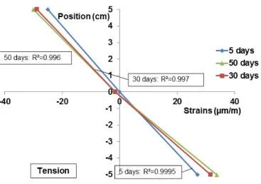
For the specimens used in the flexural creep tests, three strains were measured: on the upper, the neutral and the lower fibers of each specimen (Figure 6). The three strains fit a linear distribution along the vertical direction quite well (Figure 9). The consistency of the three measurements is thus illustrated and plane cross-sections appear to remain plane during the experiment.
IV Specific basic creep and recovery
The raw data presented previously (i.e. without subtracting the instantaneous strain and shrinkage strain) are affected by the coupling between creep, shrinkage and concrete aging (increase in strength and stiffness). The delayed deformations can be compared more easily after the instantaneous and shrinkage strains have been subtracted. This approach assumes that the different terms given by the following equation [38] are decoupled
εtot =εvs + εshr= εi + εcr + εshr (1)
Where εtot is the total strain under load, εvs the viscoelastic strain including instantaneous
strain εi and creep εcr, and εshr represents shrinkage. This way of decoupling creep from
shrinkage assumes that the shrinkage of a loaded specimen is equal to the shrinkage of an unloaded specimen [3, 42], which cannot be verified in practice. Each specimen in tensile creep was associated with a control stress-free specimen (same shape and size and cast in the same batch in order to minimize scatter). The shrinkage subtracted to the total strain of each specimen was the mean of the two measurements performed on the control specimen kept in the same thermally insulated box to be as representative as possible of the specimen under loading. Moreover, in order to compare compressive and tensile creep, which were performed to different stress levels (about 35 MPa, i.e. 50% of the compressive strength, and 1.5 MPa,
12 i.e. 50% of the tensile strength), usual practice is to divide creep strains by the applied stress so as to obtain the specific creep strains.
The absolute value of the specific creep strains in compression, direct tension and bending have been plotted in Figure 10:
- Typical compressive creep curves including initial high kinetics were obtained.
- Tensile basic creep evolved in practically the same way with fast positive strains during the first five days. After 10 days, strains appeared to be stabilized but, after about 20 days, negative creep strain rates were slowly obtained.
- For the bending creep test, compressive and tensile strains behaved similarly, with high kinetics during the first 10 days (Figure 10). In contrast to creep strains obtained in direct tension, the specific creep strains rates in tension were positive throughout the test period (80 days). No significant difference was revealed between creep strains in flexurally induced compression (FIC) and flexurally induced tension (FIT).
Tensile and flexural creep strains were identical during the first few days. After about 10 days, tensile creep strains showed a downward trend while flexural creep strains in compression and in tension continued to increase. Compressive creep strains showed the same trend as flexural creep but with larger strains: specific creep strains in direct compression appeared to be twice as large as flexural creep strains.
For the bending creep tests, strains on the most compressed fiber and those on the most tensioned fibers were confirmed by the strains calculated along the neutral axis (Figure 11). The R² regression coefficients were very close to one for all three cases. This means that the viscoelastic strains followed the usual assumption of linearity of strains over the specimen height. The positive and negative strains appeared to be quite symmetric and the strains calculated along the neutral axis were equal to zero throughout the experiment, which is equivalent to saying that the neutral fibers were not moved by the creep phenomenon. This shows that the basic creep strains were the same in tension and in compression in the bending specimens. Additionally, the neutral axis strains of the bent specimens were identical to the strains measured on the stress-free specimen.
Similar comparisons were made during the recovery phase for the three types of tests. According to Figure 12, all the specific strains again remained of the same magnitude.
13
V Discussion
The results obtained during the compressive and flexural creep tests are consistent with usual creep measurements. The initial high increase in strains is followed by a second phase where the kinetics is slower. The tensile creep tests exhibit negative strain variations, which may be regarded as surprising. However, a review of the literature shows that similar cases have been found in the past in basic creep tests [28] and in drying creep tests [45, 46].
According to Reinhardt and Rinder [28], the creep strains increase cannot be negative. The probable explanation relies on the assumption that the shrinkage strain of loaded specimens could be greater than the shrinkage strain of control specimens. In such conditions, subtracting the shrinkage strain measured on control specimens from the total strains measured on the specimens subjected to tensile creep tests would not reflect reality. This operation does not fully compensate for the shrinkage strain experienced by the specimen subjected to the creep test and therefore does not give access to the concrete basic creep.
The assumption that the shrinkage strain of a loaded specimen can be different from that of a control specimen is supported by strong arguments. It is well established that loading, even below the load bearing capacity, can induce cracks which are mainly localized at the paste-aggregate interface [25, 47]. According to Cook [48], microcracking occurs at a stress/strength ratio of 0.20 or less in the case of tensile loading. These loading-induced cracks and pre-existing cracks created by restrained shrinkage of the paste could cause an internal hydric imbalance in concrete due to local hydric shocks resulting in a phenomenon similar to drying and whose kinetics depend on the mechanism involved (gradients of pressure and/or gradients of concentration in water molecules) [32]. In turn, this internal hydric imbalance could amplify the shrinkage strains in the loaded specimens. These cracks could also cross anhydrous grains. In this way, grains that are still anhydrous are made more accessible to water, a mechanism that increases the kinetics of hydration and thus self-drying shrinkage. Therefore, the more microcracked the concrete, the more the shrinkage would be increased. In this way, the usual equation for decoupling (Equation 1) is not useable and the part of the shrinkage stains εshr should be changed to εshr/stress, the shrinkage strains under
stress as proposed by Rossi et al. [32]. Similar approaches based on further shrinkage of a loaded specimen in drying conditions [45, 46, 49] have been used to explain the Pickett effect [50]. However, in the case of drying creep, the shrinkage is caused by water mass loss while, in autogenous conditions, the shrinkage is induced by capillary depression due to water
14 migration to newly created cracks and/or water consumption by the hydration of anhydrous grains. The difficulty is then to estimate this shrinkage under stress.
In the case of the flexural creep test, this mechanism does not seem to impact the measured strains as much as for the tensile creep test. To ensure a tensile stress rate of 50% on the most tensioned fiber, the concrete under the bending creep tests can be considered as loaded at a small stress rate.As the measured compressive strength was 20 times larger than the tensile strength, the compressed zone was subjected to low loading, of about only 2% of the compressive strength. Concerning the tensioned zone, only the lowest fiber is really loaded to 50% of the tensile strength. As the cross-section remains plane, only a quarter of the specimen height is subjected to loading greater than 25% of the material strength. In the bending test, more than 75% of the specimen section is subjected to low stresses which create limited damage and cracks. This assumption probably explains why, in the flexural short test, the material’s behavior deviated from linearity at strains and stresses higher than those in the direct tension short test [51]. In addition, Bascoul and Maso [52] have shown that a strain gradient enables stable development of microcracking during a bending test. The viscoelastic strains obtained along the neutral fiber were null (Figure 11). Along the neutral fiber, the total strains were equal to the shrinkage measured on the stress-free reference specimens. This confirms that the shrinkage is the same in the unloaded part of the specimens subjected to the bending test. Consequently, the additional shrinkage strain induced by the cracking is strongly moderated. Thus the difference of creep strain kinetics in direct tension and bending-induced tension can be explained.
VI Conclusion
The aim of this experimental work was to study and to quantify the tensile creep of concrete involved in all the mechanisms of concrete cracking. In order to achieve this objective, two specific devices were developed, one for tensile creep and one for flexural creep. In comparison with compressive creep strain, for a given loading rate, strains related to tensile loading are low and particular attention was paid to avoiding thermal effects due to temperature variations and to measuring shrinkage strains as accurately as possible. Relevant results were obtained during the experimentation:
- Compressive and flexural tests showed the usual trend for creep strains: fast initial kinetics followed by a more or less stable phase.
15 - Tensile creep tests exhibited negative strain variations.
The results show that shrinkage plays an important role in the estimation of specific basic creep and particularly for tensile creep tests. The usual creep-shrinkage decoupling assumption can be considered as relevant only if the loaded specimen does not undergo significant damage (within the limits of the tests performed, case of bending test with loading level lower than 50%). Uniform loading such as in a direct tensile test causes greater damage and makes the interpretation of results more complicated because of stronger interaction between stress-induced cracking and shrinkage strains. This confirms the assumption made by Rossi et al. of larger shrinkage strains in (uniformly) loaded specimens than in stress-free control specimens [32]. The results also show that flexural creep tests could minimize this interaction due to their lower stress level. Finally, the creep recovery measured during this test was practically the same for the compressive, tensile and bending tests in terms of kinetics and magnitude.
Ongoing work is focusing on the use of the devices developed in order to extend our knowledge of tensile creep. A first priority is to deepen the understanding of the interaction between the concrete damage, its shrinkage strain and their impact on the creep strain. One way to achieve this goal is through experiments on creep with variable loading rates, especially high loading rate causing significant damage, in the three configurations presented in this paper: direct tensile creep, flexurally induced tension creep and flexurally induced compressive creep.
VII Acknowledgments:
This work was carried out at LMDC Toulouse with financial support from Andra in the framework of a group of ‘cementitious materials structures behaviour’ research laboratories.
VIII References
[1] Ollivier JP, Maso JC, Bourdette B. Interfacial transition zone in concrete. Adv Cem Based Mater 1995;2:30–8.
[2] Liners AD. Microcracking of concrete under compression and its influence on tensile strength. Mater Struct 1987;20:111–6.
16 [3] Pons G, Torrenti JM. Retrait et fluage (in French). In: Ollivier JP & Vichot A. editors.
La Durabilité Des Bétons. Presse de l’Ecole Nationale Des Ponts Et Chaussées; 2008, p.167–216.
[4] Illston J. The components of strain in concrete under sustained compressive stress. Mag Concr Res 1965;17(50):21–8.
[5] Bazant Z, Current status and advances in theory of creep and interaction with fracture. In Bazant Z & Carol I editors, Proceedings of the Fifth International RILEM Symposium, Spain, 1993, p. 291–307.
[6] Smith DM, Hammons MI. Creep of mass concrete at early ages J Mat Civ Eng 1993; 5(3): 411–7.
[7] Persson B. Early basic creep of high-performance concrete. In Proceedings of the 4th
International Symposium of Utilization of High-strength/High-performance Concrete, France, 1996, p. 405–414.
[8] Coutinho AS. A contribution to the mechanism of concrete creep. Mater Struct 1977; 10(1):3–16.
[9] Brooks JJ. 30-year creep and shrinkage of concrete. Mag Concr Res 2005;57(9):545– 56.
[10] Vandewalle L. Concrete creep and shrinkage at cyclic ambient conditions. Cem Concr Compos 2000;22(3):201–8.
[11] Bissonnette B, Pigeon M. Tensile creep at early ages of ordinary, silica fume and fiber reinforced concretes. Cem Concr Res 1995;25(5):1075–85.
[12] Granju JL. Essais de traction directe sur des pâtes pures de ciment durcies (in French). Mater Struct 1977;10(56):73–8.
[13] Illston J. The creep of concrete under uniaxial tension. Mag Concr Res 1965;17(51): 77–84.
[14] Ward MA, Cook DJ. The mechanism of tensile creep in concrete. Mag Concr Res 1969;21(68):151–8.
[15] Bissonnette B, Pigeon M. Le comportement viscoélastique du béton en traction et la compatibilité déformationnelle des réparations (in French). Mater Struct 2000; 33(2):108–18.
[16] Pigeon M, Bissonnette B. Tensile creep and cracking potential. Concr Int 1999;21(11): 31–5.
17 [17] Baluch M, Rahman MK, Al-Gadhib A. Risks of cracking and delamination in patch
repair. J Mater Civ Eng 2002;14:294–302.
[18] Bissonnette B, Pigeon M, Vaysburd AM. Tensile creep of concrete: study of its sensitivity to basic parameters. ACI Mater J 2007;104(4):360-8
[19] Altoubat SA, Lange DA. Tensile basic creep: measurements and behavior at early age ACI Mater J 2001;98(5):386–93.
[20] Østergaard L, Lange DA, Altoubat SA, Stang H. Tensile basic creep of early-age concrete under constant load. Cem Concr Res 2001;31(12):1895–9.
[21] Pane I, Hansen W. Early age creep and stress relaxation of concrete containing blended cements. Mater Struct 2002;35(2):92–6.
[22] Tao Z, Weizu Q. Tensile creep due to restraining stresses in high-strength concrete at early ages. Cem Concr Res 2006;36(3):584–91.
[23] Briffaut M, Benboudjema F, Torrenti JM, Nahas G. Numerical analysis of the thermal active restrained shrinkage ring test to study the early age behavior of massive concrete structures. Eng Struct 2011;33:1390–401.
[24] Domone PL. Uniaxial tensile creep and failure of concrete. Mag Concr Res 1974; 26(88):144–52.
[25] Al-Kubaisy MA, Young AG. Failure of concrete under sustained tension. Mag Concr Res 1975;27(92):171–8.
[26] Morin D, Maso JC. Fluage en traction des bétons ordinaires et des bétons légers (in French). Mater Struct 1982;15(89):469–73.
[27] Kristiawan SA. Strength, shrinkage and creep of concrete and in compression. Civ Eng Dim 2006;8(2):73–80.
[28] Reinhardt HW, Rinder T. Tensile creep of high-strength concrete. J Adv Concr Technol 2006;4(2):277–83.
[29] Brooks JJ, Neville AM. A comparison of creep, elasticity and strength of concrete in tension and in compression. Mag Concr Res 1977;29(100):131–41.
[30] Reviron N, Etude Du Fluage Des Bétons En Traction. Application Aux Enceintes De Confinement Des Centrales Nucléaires à Eau Sous Pression (in French). PhD thesis ENS Cachan, 2009.
[31] Reviron N, Nahas G, Tailhan JL, Le Maou F. Experimental study of uniaxial tensile creep of concrete. In Proceedings of the 8th International Conference on Creep,
18 Shrinkage and Durability of Concrete and Concrete Structures Concreep 8, Japan, 2008, p. 453-457.
[32] Rossi P, Tailhan JL, Le Maou F, Gaillet L, Martin E. Basic creep of concretes investigation of the physical mechanisms by using acoustic emission. Cem Concr Res 2012;42:61–73.
[33] Toutlemonde F, Le Maou F. Protection des éprouvettes de béton vis-à-vis de la dessiccation. Le point sur quelques techniques de laboratoire (in French). Bulletin des
laboratoires des Ponts et Chaussées, 1996 p.105–119.
[34] Camps G. Etude des interactions chemo-mécaniques pour la simulation du cycle de vie d’un élément de stockage en béton (in French). PhD thesis Université de Toulouse, 2008.
[35] Ladaoui W. Etude expérimentale du comportement thermo-hydro-mécanique à long terme des BHP destinés aux ouvrages de stockage des déchets radioactifs (in French). PhD thesis Université de Toulouse, 2010.
[36] Ladaoui W, Vidal T, Sellier A, Bourbon X. Effect of a temperature change from 20 to 50°C on the basic creep of HPC and HPFRC. Mater Struct 2011;44(9):1629–39.
[37] Munoz P. Rhéologie des bétons durcis: approche couplée de la modélisation des retraits et fluages de bétons à hautes et très hautes performances (in French). PhD thesis Université de Toulouse, 2000.
[38] Rilem TC-107 CSP. Measurement of time-dependent strains of concrete. Mater Struct 1998; 31:507–12.
[39] Elvery RH, Haroun W. A direct tensile test for concrete under long and short term loading. Mag Concr Res 1968;20(63):111–6.
[40] Atrushi DS. Tensile and Compressive Creep of Early Age Concrete: Testing and Modelling. PhD thesis The Norwegian University of Science and Technology Trondheim, 2003.
[41] Kovler K. Tensile system for determining the mechanical behavior of early age concrete under restrained and free uniaxial shrinkage. Mater Struct 1994;27(6):324–30.
[42] Kovler K. Why sealed concrete swells. ACI Mater J 1996;93(4):334–9.
[43] Acker P, Ulm FJ. Creep and shrinkage of concrete: physical origins and practical measurements. Nucl Eng Des 2001;203:143–58.
[44] Rilem CPC8. Modulus of elasticity of concrete in compression. Mater Struct 1975;6(30).
19 [45] Kovler K. Interdependence of creep and shrinkage for concrete under tension J Mater
Civ Eng 1995;7(2): 96–101.
[46] Kovler K. A new look at the problem of drying creep of concrete under tension J Mater Civ Eng 1999;11(1): 84–7.
[47] Turatsinze A, Bascoul A. Restrained crack widening in mode I crack propagation for mortar and concrete. Adv Cem Based Mater 1996;4:77–92.
[48] Cook DJ. Some aspects of the mechanism of tensile creep in concrete. ACI Mater J 1972; 69(10):645–9.
[49] Bazant Z, Chern J. Concrete creep at variable humidity: constitutive law and mechanism. Mater Struct 1985;18(1):1–20.
[50] Pickett G. The effect of change in moisture-content of the creep of concrete under a sustained load. J Am Concrete I 1942;13(4): 333–55.
[51] Kaplan MF. Strains and stresses of concrete at initiation of cracking and near failure. Proceedings J Am Concrete I 1963;60(7):853–80.
[52] Bascoul A, Maso JC. Microcracking and cracking limit state as functions of strain gradients for concrete. Cem Concr Res 1987;17(4):661–72.
20
IX Tables
Table 1: Concrete mixture proportions
Composition of concrete in kg/m3
Cement CEM I 52.5R PM-ES (Val d'Azergues), Lafarge 400
Limestone sand 0/4 mm, Boulonnais 858
Limestone aggregate 4/12.5 mm, Boulonnais 945
Superplasticizer Glénium 27, MBT 2.2
Total water 178
X Figures
(a) (b)
21 Figure 2 : Tensile creep device
22 Figure 4: Fastening and centering of steel cap
23 Figure 6: Positions of strain measurement points
24 (a)
(b)
(c)
Figure 8: Total strains in compression at 50% of fc (a), in tension at 50% of ft (b), and in bending at 50% of ft (c)
25 Figure 9: Strain of cross-section of the bending specimens
Figure 10: Comparison of direct tensile creep (DT), direct compressive creep (DC), flexurally induced tensile creep (FIT) and flexurally induced compressive creep (FIC) in terms of specific basic creep (in absolute value)
26 Figure 11: Evolution of cross-section (viscoelastic strains)
Figure 12: Comparison of direct tensile creep (DT), direct compressive creep (DC), flexurally induced tensile creep (FIT) and flexurally induced compressive creep (FIC) in terms of specific basic recovery