HAL Id: cea-02492545
https://hal-cea.archives-ouvertes.fr/cea-02492545
Submitted on 27 Feb 2020
HAL is a multi-disciplinary open access
archive for the deposit and dissemination of sci-entific research documents, whether they are pub-lished or not. The documents may come from teaching and research institutions in France or abroad, or from public or private research centers.
L’archive ouverte pluridisciplinaire HAL, est destinée au dépôt et à la diffusion de documents scientifiques de niveau recherche, publiés ou non, émanant des établissements d’enseignement et de recherche français ou étrangers, des laboratoires publics ou privés.
thermalhydraulics
D. Bestion, L. Matteo
To cite this version:
D. Bestion, L. Matteo. Scaling considerations about LWR core thermalhydraulics. NURETH 16 -The 16th International Topical Meeting on Nuclear Reactor -Thermal Hydraulics, Aug 2015, Chicago, United States. �cea-02492545�
1 SCALING CONSIDERATIONS ABOUT LWR CORE THERMALHYDRAULICS
D. Bestion1, L. Matteo2
1 : Commissariatà l’Energie Atomique et aux Energies Alternatives, DEN-DM2S-STMF-LMES,
17 Rue des Martyrs, 38054, GRENOBLE, FRANCE 2 CEA-Saclay,
Abstract
This work is a step in a long term effort to build and validate a more physically based 3D modelling of flows in a reactor core in both single-phase and two-phase situations. Light Water Reactor (LWR) core thermalhydraulics may be simulated in system codes and component codes by 3D numerical tools using the porous body approach with various possible space resolutions.
In quasi-axial flow conditions, the radial transfers by cross-flows, by turbulent diffusion and/or by dispersion effects –including momentum, energy and void dispersion- may play a very important role in many situations of interest but are not sufficiently validated for macroscopic porous models. Turbulent diffusion and dispersion phenomena are associated to time and space filtering and their modelling should depend on the filter scale in the same way as turbulent viscosity in LES depends on the filter scale. First scaling considerations are presented which show that rather simple experiments without rod heating, without high pressure steam-water conditions, can bring valuable validation data on radial transfers using low pressure water, water with addition of a passive scalar, water mixed with some heavier component, and low pressure air-water. In particular non-dimensional numbers are identified to simulate most important effects when crossflows exist in presence of density differences.
A critical review of available data and models shows that available interfacial friction models are rather empirical and have a high uncertainty due to the absence of a “flow regime map” for two-phase flow in a rod bundle. Non-dimensional numbers which should be respected in future experimental programs are discussed.
Keywords: Two-phase flow regime, Core Thermalhydraulics, Scaling, 3D in porous body 1. INTRODUCTION
System codes are currently used for accidental transient simulations of LWR reactors. 3D Pressure Vessel Modules were first used with a very coarse nodalization to capture only very large scale 3D phenomena, e.g. the flow in the annular downcomer during the refill phase of a Large Break Loss of Coolant Accident (LBLOCA), the 3D effects in the Upper Plenum, the effects of core radial power profile during a Small Break Loss of Coolant Accident (SBLOCA) or LBLOCA. A typical nodalization was about 20 meshes in axial direction (including about 10-12 in the core, 5 meshes in radial direction (10 meshes along a diameter) and 6 or 8 azimuthal meshes for 3-loop or 4-loop reactors. Such a coarse nodalization was due to the CPU cost. The computer power
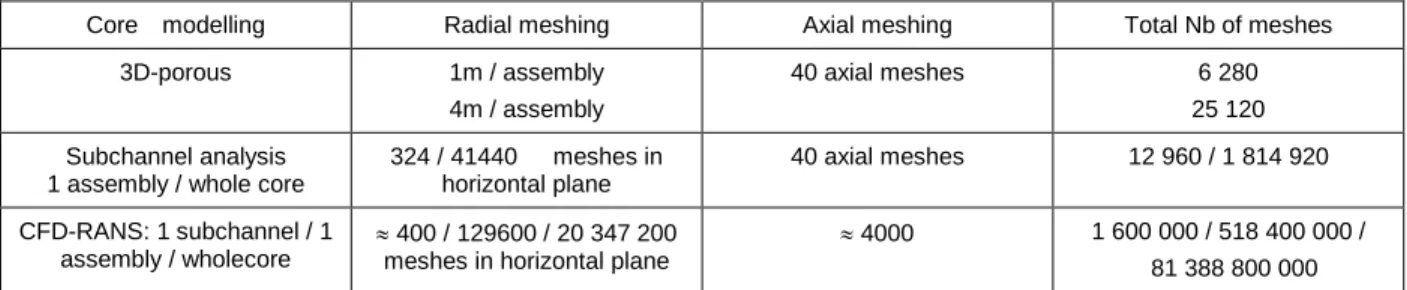
2 continuous increase now allows much finer nodalizations with a core nodalization which may be one mesh/assembly and 40 axial meshes, i.e; 6000 to 10000 meshes for the Core (Dor et al.,[1]). 40 axial meshes was found to provide a reasonably good convergence of peak clad temperature (a few degrees) during LOCA simulations whereas 10 axial meshes could result in numerical errors of about 30K. Even finer nodalizations already exist up to subchannel analysis code or even Computational Fluid Dynamics (CFD) in open medium. However the Table 1 shows estimations of required number of meshes for a 3-loop PWR core having 157 assemblies of 17X17 fuel rods. In the estimations for CFD RANS (Reynolds Average Navier Stokes), it is considered that 400 meshes per sub-channel cross section provides a good mesh convergence. A coarser nodalization is sufficient far from spacer grids but a good prediction of spacer grid effects requires small local meshes. One considers that the industrial use of a system code allows transient simulations within hours (say <12 hours) of common engineer computers so that many sensitivity tests can be performed or uncertainty propagation using a Monte-Carlo type method (a hundred runs are usually performed) can be performed.
Table 1: Estimations of the required number of meshes for core thermalhydraulic simulations at different scales
Core modelling Radial meshing Axial meshing Total Nb of meshes 3D-porous 1m / assembly
4m / assembly
40 axial meshes 6 280 25 120 Subchannel analysis
1 assembly / whole core
324 / 41440 meshes in horizontal plane 40 axial meshes 12 960 / 1 814 920 CFD-RANS: 1 subchannel / 1 assembly / wholecore 400 / 129600 / 20 347 200 meshes in horizontal plane
4000 1 600 000 / 518 400 000 / 81 388 800 000
These estimations are very rough and can be discussed but anyway some clear conclusions can be drawn.
CFD-RANS applications to a whole core or even to an assembly remain limited to a few design investigations.
Sub-channel analysis applications to a whole core may be envisaged in a few cases using HPC but not for systematic safety analyses due to the CPU cost.
System codes may now simulate core thermalhydraulics with 1m / assembly or even 4m / assembly, and possibly with local refinements with one or a few assemblies treated with subchannel analysis modelling.
A multi-scale approach (Bestion, [2 ,3]) may be used in a few cases with coupling of several scales in view of zooming on a particular location
An upscaling method may be applied using microscale (say CFD-RANS) simulations to help modelling at sub-channel scale and using sub-channel scale simulations to help modelling at porous-3D scale
The use of all these approaches requires validation data in single-phase and two-phase conditions which are very scarce in such complex geometry and PSBT and BFBT void fraction data have shown that CFD predictions with all existing types of models still have significant discrepancies with data (Valette, [4, 5]). PSBT and BFBT were the first void fraction data in a heated rod bundle with high velocities. Previous validation of void prediction was limited to tests conditions at low velocity when the measured pressure differences along the axis was mainly due to gravitational
3 P with a negligible effect of wall friction. At higher velocity, when both the frictional and gravitational Ps are playing a role, the simultaneous measurement of pressure and void fraction is necessary to validate both wall friction losses and interfacial friction which affects the slip ratio and the void fraction. Looking at CATHARE predictions of PSBT and BFBT tests, there is a systematic trend to underestimate the void fraction (and the interfacial friction) in such high velocity conditions. One may suspect that high velocity breaks bubbles into smaller bubbles and consequently increases the interfacial drag force; this effect was not seen in low velocity conditions and was not modelled. Also there were a few other effects which were seen in available low velocity data but which are not modelled by lack of understanding of the physical processes. For example the void fraction at a given steam quality in a core is higher if it was produced by a high heat flux over a short distance that when it is produced by a low heat flux over a long distance. This may be attributed to the relaxation times related to coalescence of the bubbles which detach from the heating walls and which collide with larger transported bubbles. A similar effect is observed in a depressurization of a heated rod bundle: the void fraction at a given steam quality in a core is higher in case of a rapid depressurisation than in a slower depressurisation. This may also be attributed to the relaxation times related to coalescence of the bubbles produced by flashing which collide with larger transported bubbles. Such relaxation times can only be taken into account by addition of a transport equation for interfacial area (Serre & Bestion [6], Bestion & Serre [7]) or any quantity which predicts the evolution of the bubble size. In order to develop such models a more fine description of the two-phase flow in rod bundle is necessary using advanced instrumentation.
Large scale 3D effects due to power profile were investigated for core uncovery (at low pressure only) by rectangular tests (Morel et al, [8]), and for core Reflooding by PERICLES-rectangular tests (Morel & Bestion, [9]), SCTF and CCTF tests (Murao, [10]). The validation of 3D modules of system codes against these data was performed (Morel & Boudier [11], Dor & Germain, [12]) but very few measurements were available: clad thermocouples, some pressure difference transducers and inlet and outlet conditions. This was sufficient for a global validation but not for a separate effect validation. In particular all radial transfers of momentum, mass, and energy associated to the radial power profile were not validated separately. Moreover, some radial transfers during core uncovery at relatively high pressure are predicted by the codes but are not validated since PERICLES, SCTF and CCTF were limited to low pressure (P3bar). There is a clear need of experiments which can do separate effect validation of all radial transfers using modern advanced measurement techniques.
The validation needs mentioned above were already presented in detail by Bestion [13] and advanced measurement techniques were also listed to meet the requirements of new separate-effect experimental data on core thermalhydraulics. This paper presents reflections in order to build an experimental program able to validate radial transfers in a separate-effect way and to build a flow regime map which could allow to improve interfacial friction and void fraction prediction.
2. THE RADIAL TRANSFERS IN A CORE
The various sources of radial transfers in 3D models for porous body may be identified in the 3D system of equation (Chandesris et al. [14, 15]):
𝜕𝜙𝛼𝑘𝜌𝑘
𝜕𝑡 + ∇. (𝜙𝛼𝑘𝜌𝑘𝑉𝑘) = 𝜙Γ𝑘
4
𝛼𝑘 𝜌𝑘(𝜕𝑉𝜕𝑡𝑘+ 𝑉𝑘𝛻. 𝑉𝑘) +𝛼𝑘 𝛻𝑃 = (𝑝𝑖+ 𝑓𝑖𝑇𝐷) 𝛻𝛼𝑘∓ 𝜏𝑖 + 𝛼𝑘 𝜌𝑘𝑔 + 𝜏𝑤𝑘 +𝜙1𝛻. (𝛼𝑘𝜌𝑘𝜏𝑘𝑡+𝑑)(2)
𝜕𝜙𝛼𝑘𝜌𝑘𝑒𝑘
𝜕𝑡 + ∇. (𝜙𝛼𝑘𝜌𝑘ℎ𝑘𝑉𝑘) = 𝜙q𝑘𝑖+ 𝑆𝑐q𝑤𝑘+ 𝜙Γ𝑘ℎ𝑘+ ∇. (𝛼𝑘𝑞𝑘
𝑡+𝑑) (3)
In these equations, 𝛼𝑘,𝜌𝑘,𝑉𝑘, 𝑒𝑘, ℎ𝑘 are the volume fraction, the density, the velocity, the
internal energy and the enthalpy for the phase k, 𝜙 is the porosity, P the pressure, Γ𝑘 the
interfacial mass exchange. 𝑝𝑖 and 𝑓𝑖𝑇𝐷are void dispersion terms due to space averaging of
interfacial pressure forces, and time averaging of drag and added mass forces. They tend to
homogenize void fraction. 𝜏𝑖 𝑖𝑠 the interfacial friction force, 𝜏𝑤𝑘the wall friction force, q𝑘𝑖, q𝑤𝑘
the interfacial and the wall to phase k heat transfer, 𝑆𝑐 the heating surface, 𝜏𝑘𝑡+𝑑the stress tensor
which accounts for turbulent and dispersive effects, and 𝑞𝑘𝑡+𝑑the turbulent and dispersive heat flux
Diffusion and dispersion terms
The momentum and energy turbulent and dispersive diffusive terms came out during the double (time and space) averaging process of the local convection terms:
< 𝑣𝑣̅̅̅ >𝑓=< 𝑣̅ >𝑓< 𝑣̅ >𝑓+< 𝑣′𝑣′̅̅̅̅̅ >𝑓+< 𝛿𝑣̅̅̅ 𝛿𝑣̅̅̅ >𝑓 (4)
< 𝑣ℎ̅̅̅̅ >𝑓=< 𝑣̅ >𝑓< ℎ̅ >𝑓+< 𝑣̅̅̅̅̅ >′ℎ′
𝑓 (5)
𝑋 ̅is the time average of the quantity X and X’ the deviation from this average:
< 𝑋 >𝑓is the spatial average of the quantity X and 𝛿𝑋 the deviation from this average
The first rhs terms of equations (4) and (5) are the macroscopic convection of the mean velocity and enthalpy, the second rhs terms are the turbulent diffusion of momentum and energy, and the third rhs terms are momentum and energy dispersion terms (Drouin et al, [16]).
Chandesris et al. [15] synthesized the present status of modelling and validation of these momentum and energy diffusion and dispersion terms for a Pressurized Water Reactor (PWR) core. The macroscopic Reynolds stress tensor is modelled following the microscopic eddy-diffusivity concept. The dispersive momentum term can be modelled in a similar way introducing a dispersive momentum coefficient.
𝜏𝑘𝑡+𝑑 = (𝜈𝑡𝑘𝜙 + 𝜈𝑑𝑘𝜙) [𝛻(𝜙𝑉𝑘) + 𝛻𝑇(𝜙𝑉𝑘) −23𝛻. (𝜙𝑉𝑘)𝐼] (6)
The macroscopic turbulent energy flux is modelled according to a generalized Fick’s law using a
macroscopic turbulent thermal conductivity 𝛼𝑡𝑘𝜙. The dispersive heat flux can also be modelled
using a first gradient hypothesis. Some models consider a thermal dispersive tensor 𝐷̿𝑑𝑘𝜙 to
account for anisotropic geometries.
𝑞𝑘𝑡+𝑑 = (𝛼𝑡𝑘𝜙𝐼 + 𝐷̿𝑑𝑘𝜙 )𝜙𝛻ℎ𝑘 (7)
If another scalar is transported by one or both phases (e.g. boron concentration, chemical and/or radioactive species, non-condensable gas…) similar terms are present in the transport equation of the mass concentration, which require similar models:
𝜑𝑘𝑡+𝑑 = (𝑑𝑡𝑘𝜙𝐼 + 𝐷̿𝑑𝑘𝜙)𝜙𝛻𝑋𝑘 (8)
It was found that dispersive fluxes usually dominate the macroscopic turbulent heat flux by two or three order of magnitude. It is also clear that spacer grids play a dominant role on dispersion effects and that dispersion is highly geometry-dependant. The presence of mixing vanes is playing a dominant role.
5 The available models were obtained from 5X5 or at maximum 8X8 rod bundle data analysed at the sub-channel scale. In the same way as turbulent viscosity depends on the filter scale in single phase Large Eddy Simulation, diffusion-dispersion coefficients should depend on the spatial scale of the model. When a core is modelled with a porous-3D approach at a much larger scale (one assembly/ mesh, several assemblies/ mesh) than the sub-channel scale, the coefficients should be different. Today there is no general diffusion-dispersion model validated for every type of meshing and the applicability of current models to large scale nodalizations is not proved. There is a lack of data obtained in large dimension rod bundles with measurement of diffusion and dispersion effects. One can add that diffusion-dispersion of other scalar quantities such as boron concentration also needs validation.
Regarding the void dispersion term 𝑝𝑖 and 𝑓𝑖𝑇𝐷, which are related to spatial and temporal
fluctuations of pressure and velocity at the interface, Valette [5] proposed some models for core geometry based on PSBT and BFBT benchmark data analysis at the subchannel scale. However extension of the models and validation to larger scale modelling is also required.
The radial transfers of phase momentum may be due to: Transport terms if there are crossflows
Radial diffusion terms Radial dispersion terms
Interfacial transfers between phases due to radial void dispersion force The radial transfers of phase enthalpy may be due to:
Transport terms if there are crossflows Radial diffusion terms
Radial dispersion terms
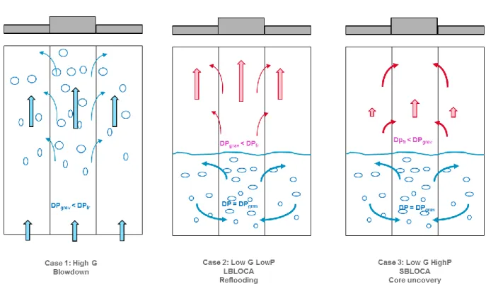
Figure 1 shows some situations of interest where radial transfers exist. Cross-flows are created to equalize pressure between adjacent assemblies with different power. A higher power induces a lower fluid density, then a higher velocity, then a higher friction pressure loss, and a lower gravitational pressure loss. In high velocity conditions, the frictional pressure loss is dominant and cross-flows go from high power assemblies to low power assemblies, which result in a negative effect on hottest rods cooling. This is the case for blowdown phase of a LBLOCA or in the dry zone of core during reflooding. In low velocity conditions, the frictional pressure loss is lower than gravitational pressure loss and cross-flows go from low power assemblies to high power assemblies which has a positive effect on hottest rods cooling. This is a typical “chimney effect”. It happens is the case of the uncovered zone of a core at relatively high pressure with relatively high steam density and low velocity.
One can identify the two behaviours (chimney effect or diverging effect in high power regions) by the relative effects of a density change on gravitational P and friction P. Power decreases the density which decreases the gravitational P and increases the friction P.
𝜕𝑃 𝜕𝑧
= 𝜌𝑔 − 𝜌 (
𝐾𝑆𝐺𝑧 ∆𝑧𝑆𝐺+
4 𝐷ℎ𝑧𝐶
𝑓𝑧)
𝑉2 2(9)
(
𝜕 𝜕𝑃 𝜕𝑧 𝜕𝜌)
𝐺= −𝑔 + (
𝐾𝑆𝐺𝑧 ∆𝑧𝑆𝐺+
4 𝐷ℎ𝑧𝐶
𝑓𝑧)
𝑉𝑜2 2 (10) 𝐹1 = (𝐾𝑆𝐺𝑧 ∆𝑧𝑆𝐺+ 4 𝐷ℎ𝑧𝐶𝑓𝑧)𝑉2 2𝑔 ; (11)6
𝐹1 < 1 𝑐ℎ𝑖𝑚𝑛𝑒𝑦 𝑒𝑓𝑓𝑒𝑐𝑡; 𝐹1 > 1 𝑑𝑖𝑣𝑒𝑟𝑔𝑖𝑛𝑔 𝑒𝑓𝑓𝑒𝑐𝑡
Figure 1: Situations of interest with radial transfers and cross-flows requiring additional validation: the central assembly is supposed to have a higher power than side assemblies.
Figure 2: Left: Map of situations as function of saturation temperature and velocity for steam
flow The conditions are: 𝐾𝑆𝐺𝑧 = 1; ∆𝑧𝑆𝐺 = 0.52 𝑚; 𝐷ℎ𝑧 = 11,8𝑚𝑚;, 𝑊𝑙𝑖𝑛=18500 W/m,
Z=3m; Right: Map of situations as function of saturation temperature and velocity for water
flow; a Blasius law is used for
𝐶
𝑓𝑧Figure 2 (left) shows the limit F1=1 for saturated steam in the map of velocity versus temperature. It is compared to the range of steam velocity which can be obtained in a core uncovery situation when there is a swell level at Z=3m with a decay heat power of 3%NP, 2%NP, 1%NP and 0.5%NP. These steam velocities are calculated as function of decay power using the following expression:
7
𝑉𝑣(𝑥%𝑁𝑃) =𝑥 𝑊𝑆 𝑙𝑖𝑛 ∆𝑍
𝑠𝑐𝜌𝑣ℎ𝑉𝐿 (12)
𝐾𝑆𝐺𝑧 is the pressure loss coefficient of a spacer grid (𝐾𝑆𝐺𝑧 1), 𝑆𝑠𝑐 is the cross section of a
subchannel, ℎ𝑉𝐿 the latent heat , 𝑊𝑙𝑖𝑛 the mean rod linear power (W/m), x the percentage of
nominal power, and ∆𝑍 the length of core where power is used to vaporize water
It is observed that in the domain Tsat>180°C (P>10 bar) the steam flowing in the dry zone is in the chimney regime. At lower pressure and temperatures, low power cases remain in the chimney regime whereas the highest power go to the divergence regime (reflooding case). Figure 2 (right) shows the limit F1=1 for water in the map of velocity versus temperature. Nominal velocities are in the divergence domain whereas low velocity conditions (pump coast down or natural circulation) are in the chimney regime.
3. SCALING ANALYSIS OF SOME RADIAL TRANSFERS
The basic idea is to perform tests in a 2D configuration which is able to generate lateral misbalance of some parameter to investigate radial transfers between two neighbouring assemblies. The Figure 3 shows an example with the lateral dimension being at least 2 assemblies and the inlet conditions for velocity, temperature or void fraction (or mass concentration of a mixed component) can be different in right and left assemblies. It is possible to perform some investigations without rod heating, without high pressure steam-water conditions, using the following conditions:
low pressure single-phase water with possible addition of a passive scalar
low pressure single-phase water with a density difference produced either by some moderate heating of the water or by mixing with some heavier component
low pressure two-phase air-water conditions
Let’s have a look at a single-phase situation in a homogeneous porosity with a chimney effect. In a steady situation momentum and energy equations are:
𝜌(𝑉𝛻. 𝑉) + 𝛻𝑃 = − 𝜌𝑔 + 𝜏𝑤+𝜙1𝛻. (𝜌𝜏𝑡+𝑑) (13) 𝜌 (𝑉𝜕𝑉𝜕𝑧+ 𝑈𝜕𝑉𝜕𝑥) + 𝜕𝑃𝜕𝑧 = 𝜌𝑔 − (𝐾𝑆𝐺𝑧 ∆𝑧𝑆𝐺+ 4 𝐷ℎ𝑧𝐶𝑓𝑧) 𝜌 𝑉2 2 + 𝜇𝑡𝑑 𝜕2𝑉 𝜕𝑥2 (14) 𝜌 (𝑈𝜕𝑈𝜕𝑥+ 𝑉𝜕𝑈𝜕𝑦) + 𝜕𝑃𝜕𝑥 = − (𝐾𝑅𝑂𝐷𝑥 𝑝 + 4 𝐷ℎ𝑥𝐶𝑓𝑥) 𝜌 𝑈2 2 + 𝜇𝑡𝑑 𝜕2𝑈 𝜕𝑧2 (15)
The evaluation of diffusion-dispersion terms is not easy but previous investigations have indicated that they are most often smaller than friction or gravity terms.
𝐾𝑒𝑓𝑓𝑧 = 𝐿𝑍 (𝐾∆𝑧𝑆𝐺𝑧 𝑆𝐺+ 4 𝐷ℎ𝑧𝐶𝑓𝑧) ; 𝐾𝑒𝑓𝑓𝑥 = 𝐿𝑋 ( 𝐾𝑅𝑂𝐷𝑥 𝑝 + 4 𝐷ℎ𝐶𝑓𝑥) (16)
𝐿𝑍 height of core, 𝐿𝑋 the size of an assembly, ∆𝑧𝑆𝐺 is the distance between spacer grids (0.52
m), 𝐾𝑅𝑂𝐷𝑥 is the pressure loss coefficient for horizontal flow through one raw of rods. p is the
pitch of the rod array (p 12.5 mm in PWR), Vo a reference vertical velocity. Estimation of the inertial terms in vertical momentum equation:
𝜌 (𝑉𝜕𝑉𝜕𝑧+ 𝑈𝜕𝑉𝜕𝑥) ≪ 𝜌𝑉𝑜𝐿2
𝑍 0.25 𝜌𝑉𝑜
2 (17)
Estimation of the friction terms in vertical momentum equation (assuming 𝐶𝑓𝑧 ≅ 0.005):
𝐾𝑒𝑓𝑓𝑧 𝐿𝑍 𝜌 𝑉2 2 = 𝜌 ( 𝐾𝑆𝐺𝑧 ∆𝑧𝑆𝐺+ 4 𝐷ℎ𝑧𝐶𝑓𝑧) 𝑉𝑜2 2 1.8 𝜌𝑉𝑜2 (18)
8 The ratio of friction to inertial terms is high which means that the main contributors to pressure drop are gravity and friction terms.
The ratio of gravity term to friction term is: 𝐹1 =𝐾𝑒𝑓𝑓𝑧𝑉
2
2𝑔𝐿𝑍 ≅ 0.18 𝑉
2
If power differences between neighbouring assemblies can create a density difference ρ over a
height z, it can create a radial pressure gradient 𝜕𝑃𝜕𝑥~𝐿∆𝑧
𝑋ρg
Considering here again that inertial terms are small compared to friction terms, one may simplify the horizontal momentum equation:
𝐾𝑒𝑓𝑓𝑥 𝐿𝑋 𝜌 𝑈2 2 ≅ ∆𝑧 𝐿𝑋ρg (19)
To reproduce a similar crossflow one must respect the ratio U/V or the number F2
𝐹2 = 𝑉𝑈22= 𝐾𝑒𝑓𝑓𝑥ρ𝑉2
ρg∆𝑧 (20)
Figure 3: Possible test section configuration to investigate radial transfers with a misbalance of inlet velocity, or temperature, or mass concentration, or void fraction - Identification of reactor
conditions by the couple (𝐹1 , 𝐹2) then definition of test conditions Vo and ρ/ρ
Then in single phase case with density differences, it is rather easy to create similar conditions in
the experiment (Figure 3). Respecting the values of F1 and F2 is necessary to respect the most
important effects. Preliminary tests without ρ are necessary to measure 𝐾𝑒𝑓𝑓𝑥 and 𝐾𝑒𝑓𝑓𝑧. Then
in order to evaluate the diffusion-dispersion terms, preliminary tests without ρ are necessary: Tests with homogeneous flow and a gradient of a passive scalar may bring a good
estimation of diffusion-dispersion terms of energy or any scalar
Tests with an inlet misbalance of velocity are sensitive to both transverse pressure losses and diffusion-dispersion of momentum: a measurement of pressure field and velocity field may allow to measure both effects and to validate the models for diffusion-dispersion.
9 In two-phase conditions as shown in Figure 1 the swell level in Figure 1 (center and right) a first approximation is to extend the single phase analysis to the two-phase by considering a homogeneous mixture. One may then conclude that the modified number F2 has to be respected:
𝐹2 = 𝐾𝑒𝑓𝑓𝑥𝑉
2
(ρ𝑙−ρ𝑣)g∆𝑧 (21)
But the void dispersion terms have to be estimated possibly in absence of crossflows: the idea is to create two columns on right and left assemblies which have different void fraction and different velocities so that the sum of friction and gravity pressure losses are equal. In such a case, only the void dispersion term can induce void mixing between the assemblies.
Further scaling analyses are still necessary to address in more detail all reactor situations of interest.
4. THE TWO-PHASE FLOW REGIME IN ROD BUNDLE
There is no flow regime map for flow in rod bundles and only very few studies were devoted to the identification of the flow structure in such complex geometry. This is the reason of the empirical nature of available interfacial friction models and of the rather high uncertainty of the void fraction predictions. No improvement is possible without a better understanding of the two-phase flow structure in rod bundle, particularly in the domain of void fraction from bubbly to churn flow (0< 𝛼 < 0.8). Void fraction and slip between phases depend mainly on the size of bubbles and on the drag coefficient. Equating drag and buoyancy forces gives:
𝐹𝐷 = 1 8⁄ 𝜋𝛿2𝜌𝑙𝐶𝑑∆𝑉2 = 𝐹𝐵 = 1 6⁄ 𝜋𝛿3(𝜌𝑙− 𝜌𝑣)𝑔 → ∆𝑉 = √8(𝜌6𝜌𝑙−𝜌𝑣)𝑔𝛿
𝑙𝐶𝑑 (22)
The bubble size 𝛿 is difficult to evaluate and there is necessarily a spectrum of bubble sizes in a
core with small bubbles detached from heating wall up to maximum bubble size 𝛿𝑚𝑎𝑥 authorized
by break-up mechanisms. In case of break up by Rayleigh-Taylor instability, 𝛿𝑚𝑎𝑥~ℒ =
√∆𝜌𝑔𝜎 and ∆𝑉𝑚𝑎𝑥~ [∆𝜌𝑔𝜎𝜌
𝑙2 ]
1 4 ⁄ 1
√𝐶𝑑 . In case of dynamic break up 𝛿𝑚𝑎𝑥 corresponds to a critical
Weber number 𝑊𝑒 =𝜌𝑙 𝛿 ∆𝑉𝑚𝑎𝑥 2 𝜎 → ∆𝑉𝑚𝑎𝑥~ [ ∆𝜌𝑔𝜎 𝜌𝑙2 ] 1 4 ⁄ 1
√𝐶𝑑 . Then in any case 𝛿𝑚𝑎𝑥 is
proportional to the Laplace scale ℒ, and assuming Cd is constant, a bubble Reynolds number may
be defined as 𝑅𝑒𝑏= 𝜌𝑙 ℒ∆𝑉𝜇
𝑙 =
√𝜌𝑙 𝜎ℒ
𝜇𝑙 which is related to the Morton number 𝑀𝑜 or viscosity
number 𝑁𝜇. 𝑅𝑒𝑏 = 𝑀𝑜−1 4⁄ = 𝑁𝜇−1. Influences of duct size D may be a function of the ratio
D/ ℒ . In pipes it is then natural to express the drift velocity in the form
Vgj = [∆𝜌𝑔𝜎𝜌 𝑙2 ] 1 4 ⁄ F(Dℒ, 𝑁𝜇) (23)
Kataoka-Ishii [17] added a small effect of the density ratio 𝜌𝑣⁄ . This effect may be understood 𝜌𝑙
by looking at a force balance for a bubble which considers all forces including inertia, lift and
added mass forces. 𝑚𝑏𝑑𝑉𝑑𝑡𝑏= 𝐹𝐵−𝐹𝐷+ 𝐹𝐿+ 𝐹𝐴𝑀. In absence of 𝐹𝐴𝑀 , a bubble at rest in stagnant
liquid would accelerate under buoyancy effect with an acceleration 𝑑𝑉𝑑𝑡𝑏≅∆𝜌𝑔𝜌
𝑣 and would reach
the equilibrium velocity after a relaxation time 𝜏𝑏 ≅𝜌𝜌𝑣
𝑙√
8𝜌𝑙𝛿
10
transit times 𝜏𝑡 ≅𝐿𝑧𝑉
𝑣 in reactor components . But added mass effects may increase a lot this time
scale 𝜏𝑏 which remains smaller than 𝜏𝑡 . However turbulent fluctuations in the liquid induce
even stronger turbulent fluctuations of the bubble velocity due to lower vapor inertia. Such bubble fluctuations favor collisions and coalescence leading to larger size and larger slip. This enhanced
coalescence and larger slip may be higher for lower 𝜌𝑣⁄ as predicted by the Kataoka Ishii 1990 𝜌𝑙
correlation. However coalescence and break up are relatively slow processes and the time scale to
reach an equilibrium bubble size repartition is probably not small compared to transit times 𝜏𝑡 in
a core which makes the prediction of interfacial friction difficult without additional equation for interfacial area density. Core two-phase flows are boiling flows and bubbles smaller than equilibrium size are continuously added. An experiment to characterize core two-phase flow should measure bubble size distribution and relaxation time scales for reaching an equilibrium size distribution.
Drift flux models for the rod bundle geometry
Many investigations were devoted to interfacial friction in rod bundle and at least three models implemented in TRACE [18], CATHARE (Bestion, [19]) and RELAP-5 (NUREG/CR-5535, [20]) system codes were developed first in the form of a drift flux model which was then translated into an interfacial friction model:
TRACE model was derived from Bestion [21] first analysis of some data in rod bundle. It was found that the usual Zuber & Findlay [22] drift flux models for slug flow and churn-turbulent bubbly flow in pipes were not applicable to rod bundle. The flow regimes were not identical in rod
bundle to the pipe flow regimes. In particular it was found that the drift velocity 𝑉𝑔𝑗 was much
higher than Zuber & Findlay [22] correlations and exhibited a much higher pressure dependence. Based on some first local void fraction measurements with optical probes in a 4X4 rod bundle, it was assumed that there could be a trend to separate flow paths for steam and water in rod bundles even in moderate void fractions (0<α<0.8) giving some similarity with the annular or inverse
annular flow regimes. Then a simple Froude similarity was used to find an expression for 𝑉𝑔𝑗
which had the right pressure trend. However the diameter dependence was not proved. Vgj = 0.188√𝑔𝐷ℎ∆𝜌
𝜌𝑔 (24)
CATHARE model was later derived from Bestion [23, 24] investigations of a larger data base
including typical PWR core rod bundles with 𝐷ℎ 12 mm, with typical Steam Generator tube
bundles with 𝐷ℎ 32 mm, and additional data with 𝐷ℎ 24 mm, and covering a large pressure
range (1<P<70 bar). These data confirmed the effect of 𝐷ℎ but a more complex correlation was
proposed: Vgj = [ 𝑔∆𝜌𝐿 𝐶𝑓𝑔𝜌𝑔𝐷ℎ𝐿+𝐾𝑔𝜌𝑔+𝐾𝑙𝜌𝑙] 1/2 ; 𝐶𝑜= 1 + 0,244 exp (−273 𝜌𝑣⁄ ) 𝜌𝑙 (25) 𝐶𝑓𝑔 = 37, 𝐾𝑔 = 13.5, 𝐾𝑙 = 0.19; 𝐿 = 𝑓(𝛼)ℒ; ℒ = √𝑔∆𝜌𝜎 ; 𝐵𝑜 = (𝐷ℎ⁄ )ℒ 2 (26) 𝑓(𝛼) = 𝑀𝑖𝑛 [18, 0.3834 + 17.6166 𝛼3(256 − 768𝛼) ]
Here at least 4 non-dimensional numbers have an effect. In addition to the Froude number, the Bond number, the void fraction, and the density ratio. However as show in equation 27, the
11 Froude number is the main number and describes most of the observed pressure and diameter effects, the other numbers being in corrective terms.
𝐹𝑟 =√𝑔𝐷√𝜌𝑔Vgj ℎ∆𝜌= 𝐶𝑓𝑔 −1 2⁄ [1 + 𝑓(𝛼)𝐵 𝑜 1 2 ⁄ (𝐾𝑔 𝐶𝑓𝑔+ 𝐾𝑙 𝐶𝑓𝑔 𝜌𝑙 𝜌𝑔)] −1 2⁄ =0.164 [1 + 𝑓(𝛼)𝐵𝑜 1 2 ⁄ (0.36 + 0.00516𝜌𝑙 𝜌𝑔)] −1 2⁄ (27)
The Chexal-Lellouche [25] model has complex expressions with several non-dimensional
numbers: 𝐾𝑢 = 𝜌𝑙1⁄2 Vgj (𝑔𝜎∆𝜌)1⁄4, 𝜌𝑙 𝜌𝑔, 𝑅𝑒𝑔 = 𝜌𝑔𝑗𝑔𝐷ℎ 𝜇𝑔 , 𝑅𝑒𝑙 = 𝜌𝑙𝑗𝑙𝐷ℎ 𝜇𝑙 , 𝐶1 = | 4𝑃𝑐𝑟𝑖𝑡𝑖𝑐𝑎𝑙2 𝑃(𝑃𝑐𝑟𝑖𝑡𝑖𝑐𝑎𝑙−𝑃)|, 𝐶7 = ( 𝐷2 𝐷ℎ) 0,6
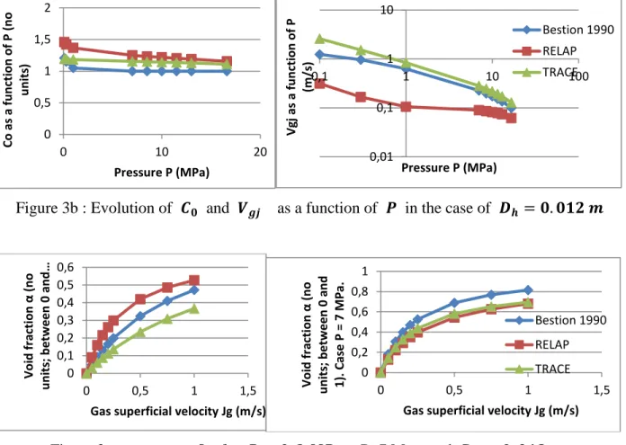
The three models above have been somewhat adapted when translated into interfacial friction models in the TRACE, CATHARE and RELAP codes. It is clear that they do not agree on the
non-dimensional numbers, and on the quantitative values of Co and Vgj.
Figure 4 compares the evolutions of Co and Vgj with diameter and pressure and shows that the
trends are really different. Figure 4 shows also some significant differences in void fraction predictions and big differences on effect of Jl on the velocity difference. This clearly demonstrate that more understanding of the flow structure is required to better model interfacial friction. It is rather surprising not to see the liquid viscosity in the two first models since a drag coefficient for a bubble usually depends on a bubble Reynolds number which uses the liquid viscosity. It may be explained by the possible existence of very large bubbles occupying several sub-channels. Such bubbles have a slip velocity which may depend more on the friction along the films left along the
rods than on the form drag. In the void fraction range from 0 to about 0.8, bubbles are expected, from
very small to very large bubbles. Looking at measured drift velocity in large rod bundles [19, 21, 23, 24], and compared to measured drift velocity in large pipes, they were found to be very similar (approximately 30 Laplace scales in size). In order to observe these maximum size bubbles, a 8X8 rod bundle is necessary in air-water conditions or a 6X6 rod bundle in higher pressure steam-water.
𝐵𝑜 and 𝑅𝑒𝑏 are expected to play a role in the flow regime and the bubble size distribution. The
Table 2 below shows how Dh/ ℒ, 𝑅𝑒𝑏 and Fr change as function of fluid, pressure and temperature
conditions. Air-water at atmospheric conditions is rather far from prototypical steam-water
conditions encountered in reactor cores for both 𝐵𝑜 and 𝑅𝑒𝑏. However boiling atmospheric
steam-water conditions are much closer to reactor higher pressure conditions for Bo. The
possibility to use test section at a larger geometrical scale 𝐷ℎ than reactor scale to make
measurement easier may be envisaged. Fr in air-water will represent only low pressure steam-water conditions. Also in high velocity conditions, liquid turbulence – characterized by liquid
Reynolds number - 𝑅𝑒𝑙= 𝜌𝑙 𝑉𝑙 𝐷ℎ
𝜇𝑙 may induce bubble break up which also affects the bubble size
and the flow regime. It is rather easy to respect this number even with different P&T conditions by playing on the Velocity.
It is expected that air-water tests may be a first step in a separate effect analysis taking advantage of easier measurements and visualization. But it should be complemented by more representative test conditions in a second phase in particular to get more prototypical Fr, Bo, and density ratio and Reb numbers. An adiabatic mixture of liquid water with Freon gas may respect Fr and the density ratio at moderate pressure and low temperature. This may be a compromise to keep reasonable cost. In a third phase, heated tests are probably necessary to see the influence of boiling, even if a reduced set of measurement techniques is available.
12 5. CONCLUSIONS
It was found that in many reactor situations radial transfers of mass, momentum and energy due to crossflows, diffusion and dispersion effects exist in a core with a radial power profile and new separate effect tests with advanced measurement techniques are necessary to validate the models in a separate effect way. Analysing crossflows in single-phase conditions in presence of density differences it was shown that one must investigate the phenomena by respecting the ratio U/V or
the number 𝐹2 = 𝑉
2
𝑈2 =
𝐾𝑒𝑓𝑓𝑥𝑉2
ρg𝑝 . When friction term is significant compared to gravity, the ratio
𝐹1 =𝐾𝑒𝑓𝑓𝑧𝑉2
2𝑔𝐿𝑍 of gravity term to friction term must also be respected.
In two-phase conditions the modified number 𝐹2 = 𝐾𝑒𝑓𝑓𝑥𝑉
2
(ρ𝑙−ρ𝑣)g𝑝 has to be respected:
In order to evaluate the diffusion-dispersion terms, preliminary tests without density differences are necessary:
Tests with homogeneous flow and a gradient of a passive scalar may bring a good estimation of diffusion-dispersion terms of energy
Tests with an inlet misbalance of velocity are sensitive to both transverse pressure losses and diffusion-dispersion of momentum: a measurement of pressure field and velocity field may allow to measure both effects and to validate the models for diffusion-dispersion. But the void dispersion terms have to be estimated possibly in absence of crossflows: the idea is to create two columns on right and left assemblies which have different void fraction and different velocities so that the sum of friction and gravity pressure losses are equal.
Further scaling analyses are still necessary to address in more detail all reactor situations of interest and to scale relevant tests. After these first investigations it seems reasonable to conclude that rather simple experiments without rod heating, without high pressure steam-water conditions, can bring valuable validation data on radial transfers using low pressure water, water with addition of a passive scalar, water mixed with some heavier component, and low pressure air-water.
The two-phase flow topology and structure of the interfaces is not well known in rod bundles. Three drift flux models used to develop three widely used system codes may have rather different effects of diameter, pressure and superficial velocity. The uncertainty of these models may significantly be improved by new experimental investigations using advanced instrumentation. In view of defining test conditions and scaling the test facility, first preliminary conclusions may be given:
The size of the bundle should be larger than the largest bubble which may be similar to what is observed in a large pipe: this corresponds to 8X8 rod bundle in air-water conditions or a 6X6 rod bundle in higher pressure steam-water.
It is expected that air-water tests may be a first step in a separate effect analysis taking advantage of easier measurements and visualization.
In order to get more prototypical conditions, an adiabatic mixture of liquid water with Freon gas may respect Fr and the density ratio at moderate pressure and low temperature. The experiment should measure bubble size distribution and relaxation time scales for
13
Table 2: Evolution of 𝐵𝑜 and 𝑅𝑒𝑏 as function of fluid, pressure and temperature conditions
Dh/ ℒ Reb √𝑔𝐷ℎ∆𝜌/𝜌𝑣 Air-water P=1b T=20°C 4.3 446 10 m/s Steam-water P=1b, T=100°C 4.7 1349 13 m/s Steam-water P=3b, T=133°C 4,9 1654 8 m/s Steam-water P=70 b, T=286°C 7.4 1532 1,6 m/s Steam-water P=150b, T=342°C 11.4 776 1 m/s REFERENCES
[1] I. Dor, M. Chandesris, P. Germain and A. Ruby, CATHARE 3D module- from CATHARE 2
V2.5_3 to CATHARE 3 V1.0, NURETH-15, Pisa, Italy, May 12-15, 2013
[2] D. Bestion, From the Direct Numerical Simulation to system codes – Perspective for the
Multi-scale analysis of LWR Thermalhydraulics, Nuclear Engineering and Technology,
VOL.42, NO.6, December 2010
[3] D. Bestion, Status and perspective for a multiscale approach to Light Water reactor
thermalhydraulic simulation, NURETH 14 topical Issue of Nuc. Eng. and Des., 2012
[4] M. Valette. “Analysis of boiling two phase flow in rod bundle for NUPEC BFBT Benchmark with 3-field NEPTUNE System code”, NURETH 12, Pittsburgh, Pennsylvania, USA, September 30-October 4, 2007.
[5] M. Valette, PSBT simulations with Cathare 3, The 14th International Topical Meeting on Nuclear Reactor Thermalhydraulics, NURETH-14, Toronto, Canada, September 25-30, 2011
[6] G. Serre , D. Bestion, “Progress in improving two-fluid model in system code using turbulence and interfacial area equations”, NURETH 11, Avignon, France, 2005.
[7] D. Bestion, G. Serre, Transport of interfacial area in system codes: status and perspectives, NURETH-15, Pisa, Italy, May 12-15, 2013
[8] C. Morel, D. Bestion, G. Serre, & I. Dor, “Application of the 6-equation Cathare 3-D module to complex flows in a reactor core under core uncovery and reflooding conditions”, AMIF-ESF Workshop on Computing methods for Two-phase Flow, Aussois, Jan 12-14, 2000
[9] C. Morel, D. Bestion, Validation of the Cathare code against Pericles 2D boil up tests, NURETH-9, Oct 99, San Francisco
[10] Y. Murao, T. Iguchi, H. Akimoto and T. Iwamura, “Large-scale multi-dimensional phenomena found in CCTF and SCTF experiments”, Nuc. Eng. and Design 145, 1993, 85-95
[11] C. Morel and P. Boudier, “Validation of the CATHARE code against PERICLES 2D
14 [12] I. Dor, P. Germain, Core radial power profile effect during Reflooding , Validation of CATHARE2 3D module using SCTF tests, NURETH-14, Toronto, Canada, September 25-30, 2011
[13] D. Bestion, Validation data needs for CFD simulation of two-phase flow in a LWR core, CFD4NRS-5, Zurich, September 2014
[14] M. Chandesris, G. Serre, P. Sagaut, “A macroscopic turbulence model for flow in porous
media suited for channel, pipe and rod bundle flows”, Int. J. Heat Mass Transfer, 49,
2739-2750, 2006.
[15] M. Chandesris, M. Mazoyer, G. Serre and M. Valette, “Rod bundle thermalhydraulics mixing
phenomena: 3D analysis with CATHARE 3 of various experiments”, NURETH15, Pisa,
Italy, May 2013.
[16] M. Drouin, O. Grégoire, O. Simonin, A. Chanoine, “Macroscopic modeling of thermal dispersion for turbulent flows in channels“, Int. J. of and Mass Transfer, 53 (2010), 2206-2217.
[17] I. Kataoka, M. Ishii, Drift flux model for large diameter pipes and new correlation for pool void fraction, Int J of Heat and mass transfer, Vol 30, N°9, pp1927_1939, 1987
[20] RELAP5/MOD3 Code Manual Volume I: Code structure, system models and solution procedure, NUREG/CR-5535, March 1998
[18] TRACE V5.0, THEORY MANUAL Field Equations, Solution Methods, and Physical Models, 2007
[19] D. Bestion, The physical closure laws in the Cathare code, Nuclear. Engineering. & Design, 124 (1990) 229-245
[21] D. Bestion, Interfacial friction determination for the 1D-6equation model used in the Cathare
code, European Two-Phase Flow Group Meeting , Southampton, june 3-7 1985
[22] N. Zuber, J.L. Findlay, Average Volumetric Concentration in two-phase systems,, J. of heat Transfer, 453-468,1965
[23] D. Bestion, Slow depressurisation experiments in vertical rod bundles and annuli, European Two-Phase Flow Group Meeting, Trondheim, June 1987
[24] D. Bestion, Recent developments on interfacial friction models, European Two-Phase Flow Group Meeting, Varese 21-24 May 90
[25] B. Chexal, G. Lellouche, A full range drift-flux correlation for vertical flows (Revision 1), EPRI Report NP-3989-SR, USA, 1986.
0 0,1 0,2 0,3 0,4 0,5 0,6 0 0,02 0,04 Vg j as a fun ction o f D h (m /s) Hydraulic Diameter Dh (m) 0 1 2 3 4 0 1 2 3 4 5 Vv -Vl ( m /s)
Liquid superficial velocity Jl (m/s) Bestion 1990
RELAP TRACE
15
Figure 3a : Left 𝑽𝒈𝒋 versus 𝐷ℎ for α=0.5 and P = 7 MPa; right Vv – Vl versus 𝐽𝑙 Dh =12 mm
Figure 3b : Evolution of 𝑪𝟎 and 𝑽𝒈𝒋 as a function of 𝑷 in the case of 𝑫𝒉 = 𝟎. 𝟎𝟏𝟐 𝒎
Figure 3c : 𝜶 versus 𝑱𝒈 for 𝑷 = 𝟎. 𝟑 𝑴𝑷𝒂 , P=7 Mpa, and 𝑫𝒉 = 𝟎. 𝟎𝟏𝟐 𝒎.
0 0,5 1 1,5 2 0 10 20 Co as a fu n ction o f P (n o u n its) Pressure P (MPa) 0,01 0,1 1 10 0,1 1 10 100 Vg j as a fun ction o f P (m /s) Pressure P (MPa) Bestion 1990 RELAP TRACE 0 0,1 0,2 0,3 0,4 0,5 0,6 0 0,5 1 1,5 Vo id fr ac tion α ( no u n its; b e tw e e n 0 an d …
Gas superficial velocity Jg (m/s)
0 0,2 0,4 0,6 0,8 1 0 0,5 1 1,5 Vo id fr ac tion α ( no u n its; b e tw e e n 0 an d 1). Case P = 7 M Pa.
Gas superficial velocity Jg (m/s) Bestion 1990 RELAP TRACE