Publisher’s version / Version de l'éditeur:
Vous avez des questions? Nous pouvons vous aider. Pour communiquer directement avec un auteur, consultez la
première page de la revue dans laquelle son article a été publié afin de trouver ses coordonnées. Si vous n’arrivez pas à les repérer, communiquez avec nous à PublicationsArchive-ArchivesPublications@nrc-cnrc.gc.ca.
Questions? Contact the NRC Publications Archive team at
PublicationsArchive-ArchivesPublications@nrc-cnrc.gc.ca. If you wish to email the authors directly, please see the first page of the publication for their contact information.
https://publications-cnrc.canada.ca/fra/droits
L’accès à ce site Web et l’utilisation de son contenu sont assujettis aux conditions présentées dans le site LISEZ CES CONDITIONS ATTENTIVEMENT AVANT D’UTILISER CE SITE WEB.
Medical Physics, 2020-01-27
READ THESE TERMS AND CONDITIONS CAREFULLY BEFORE USING THIS WEBSITE.
https://nrc-publications.canada.ca/eng/copyright
NRC Publications Archive Record / Notice des Archives des publications du CNRC :
https://nrc-publications.canada.ca/eng/view/object/?id=20cdc3ea-d58f-4b19-bbad-4f1ff88c5de4 https://publications-cnrc.canada.ca/fra/voir/objet/?id=20cdc3ea-d58f-4b19-bbad-4f1ff88c5de4
Archives des publications du CNRC
This publication could be one of several versions: author’s original, accepted manuscript or the publisher’s version. / La version de cette publication peut être l’une des suivantes : la version prépublication de l’auteur, la version acceptée du manuscrit ou la version de l’éditeur.
For the publisher’s version, please access the DOI link below./ Pour consulter la version de l’éditeur, utilisez le lien DOI ci-dessous.
https://doi.org/10.1002/mp.14048
Access and use of this website and the material on it are subject to the Terms and Conditions set forth at
A modified formalism for electron beam reference dosimetry to improve
the accuracy of linac output calibration
Accepted
Article
dosimetry to improve the accuracy of linac output
2
calibration
3
Bryan R. Muir
4
NRC Metrology Research Centre, National Research Council of
5
Canada,
6
Ottawa, ON, K1A 0R6, Canada
7
Bryan.Muir@nrc-cnrc.gc.ca
8
Last edited January 22, 2020
9
i
This article has been accepted for publication and undergone full peer review but has not been through the copyediting, typesetting, pagination and proofreading process, which may lead to differences between this version and the Version of Record. Please cite this article as doi: 10.1002/mp.14048
Accepted
Article
Purpose: To present and demonstrate the accuracy of a modified formalism for
11
electron beam reference dosimetry using updated Monte Carlo calculated beam quality
12
conversion factors.
13
Methods: The proposed, simplified formalism allows the use of cylindrical
ioniza-14
tion chambers in all electron beams (even those with low beam energies) and does not
15
require a measured gradient correction factor. Data from a previous publication are
16
used for beam quality conversion factors. The formalism is tested and compared to the
17
present formalism in the AAPM TG-51 protocol with measurements made in Elekta
18
Precise electron beams with energies between 4 MeV and 22 MeV and with fields
19
shaped with a 10×10 cm2 clinical applicator as well as a 20×20 cm2 clinical applicator
20
in the 18 MeV and 22 MeV beams. A set of six ionization chambers are used for
21
measurements (two cylindical reference-class chambers, two scanning-type chambers
22
and two parallel-plate chambers). Dose per monitor unit is derived using the data and
23
formalism provided in the TG-51 protocol and with the proposed formalism and data
24
and compared to that obtained using ionization chambers calibrated directly against
25
primary standards for absorbed dose in electron beams.
26
Results: The standard deviation of results using different chambers when TG-51
27
is followed strictly is on the order of 0.4 % when parallel-plate chambers are
cross-28
calibrated against cylindrical chambers. However, if parallel-plate chambers are
di-29
rectly calibrated in a cobalt-60 beam, the difference between results for these chambers
30
is up to 2.2 %. Using the proposed formalism and either directly calibrated or
cross-31
calibrated parallel-plate chambers gives a standard deviation using different chambers
32
of 0.4 %. The difference between results that use TG-51 and the primary standard
33
measurements are on the order of 0.6 % with a maximum difference in the 4 MeV
34
beam of 2.8 %. Comparing the results obtained with the proposed formalism and the
35
primary standard measurements are on the order of 0.4 % with a maximum difference
36
of 1.0 % in the 4 MeV beam.
37
Conclusion: The proposed formalism and the use of updated data for beam quality
38
conversion factors improves the consistency of results obtained with different chamber
39
types and improves the accuracy of reference dosimetry measurements. Moreover, it is
40
simpler than the present formalism and will be straightforward to implement clinically.
41
Keywords: TG-51, Electron beams, Reference dosimetry, Beam quality conversion factors
42 43
Accepted
Article
Contents
45 I. Introduction 1 46I.A. Review of the current formalism . . . 1
47
I.B. Description of a proposed, modified formalism . . . 3
48
I.C. Goals of this work. . . 5
49 II. Method 5 50 III. Results 10 51 IV. Discussion 13 52 V. Conclusions 16 53 VI. Acknowledgements 16 54
VII.Disclosure of Conflicts of Interest 16
55
References 17
56
VIII.Figures and tables 21
57
IX. Figure captions 25
58
Accepted
Article
I.
Introduction
59
This work investigates the accuracy of a proposed formalism and new data for electron
60
beam reference dosimetry. A review of the current formalism is presented (sectionI.A.), the
61
new formalism is described (section I.B.) and, finally, the goals of this work are laid out
62
(sectionI.C.).
63
I.A.
Review of the current formalism
64
To calibrate the output of electron beams produced by linear accelerators medical physicists
65
follow procedures laid out in reference dosimetry protocols such as the AAPM’s TG-511 66
protocol, the IAEA’s TRS-398 code of practice2 and the IPEM’s code of practice.3 These 67
protocols were published in the late 1990s or early 2000s and there have been ongoing efforts
68
to update them based on newly available data. For example, an addendum to the AAPM’s
69
TG-51 protocol for reference dosimetry of high-energy photon beams was published in 2014.4 70
A wider revision is required for electron beam reference dosimetry.
71
The AAPM’s TG-51 protocol is based on the use of an ionization chamber calibrated in
72
a cobalt-60 reference field. The linac beam is calibrated in terms of absorbed dose to water,
73
Dw, which is obtained with
74
Dw = M kQND,wCo (1)
75
where M is the fully corrected reading from an ionization chamber with a cobalt-60
calibra-76
tion coefficient, NCo
D,w, and the beam quality conversion factor, kQ, is required to convert the
77
cobalt-60 calibration coefficient to that for the beam quality, Q, of interest.
78
For electron beam reference dosimetry, the TG-51 protocol makes several additional
rec-79
ommendations and requirements that are not needed for photon beam dosimetry. These
80
are:
81
1. In equation 1, kQ is factored such that
82 Dw = M PgrQkR50N Co D,w = M P Q grkR′ 50kecalN Co D,w, (2) 83 where PQ
gr is the gradient correction factor, kR50 is the component of kQ that is inde-84
pendent of gradient effects at the point of measurement (and kR50 = kR′ 50kecal), k
′ R50 is 85
the electron quality conversion factor and kecal is the photon-electron conversion factor.
86
Accepted
Article
Differing from photon beams, where PQ
gr is included in tabulated kQ factors, a
mea-87
sured PQ
gr is required for cylindrical chambers because it is assumed to depend on the
88
ionization gradient and the cavity radius of the chamber. For parallel-plate chambers
89
the gradient correction factor is assumed to be unity because, when positioned with the
90
inside of the front face of the window at the point of measurement, they are assumed
91
to sample the same electron fluence as in water. The parameter kR50 is further factored 92
into k′
R50kecal because the chamber-to-chamber variation of k
′
R50 is much less than that 93
for kR50 and kecal is required for cross-calibrating parallel-plate chambers against cylin-94
drical chambers. The TG-51 protocol also states that kecal is directly measurable by
95
primary standards labs and, since the publication of TG-51, at least three standards
96
labs have developed this capability.5–7 It is fixed for a given chamber model (although 97
measurements of kecal might be subject to chamber-to-chamber variations for
cham-98
bers of the same type) and is equal to kR50 for an electron beam of quality Qecal. The 99
parameter k′
R50 is beam quality dependent. Beam quality is specified with the depth 100
at which the absorbed-dose falls to 50 % of the maximum dose, R50.
101
2. Parallel-plate chambers are recommended to be cross-calibrated against cylindrical
102
chambers in a high-energy electron beam. By cross-calibrating a parallel-plate chamber
103
against a cylindrical chambers one obtains
104 (kecalND,wCo)pp = (M PQ grkR′50kecalN Co D,w)cyl (M k′ R50) pp . (3) 105
This recommendation, which avoids the need for a calculated (generic) kecal factor,
106
is based on early evidence8 that minor construction details significantly affect the 107
response of these chambers in cobalt-60 beams, which would give rise to higher
un-108
certainties in calculations of kecal. More recent publications9–14 have demonstrated
109
that for modern parallel-plate chambers (perhaps because of improved manufacturing
110
techniques) this is no longer as much of an issue.
111
3. A measured gradient correction factor is required for cylindrical chambers. It is
deter-112
mined with
113
Pgr =
Mraw(dref + 0.5rcav)
Mraw(dref)
, (4)
114
where Mraw is the raw ionization chamber reading and rcav is the cavity radius of
115
the ionization chamber. Measurements of ionization chamber response are required at
116
Accepted
Article
two depths. Misinterpretation of how the gradient correction factor is measured and
117
applied is one of the most common sources of error made in electron beam reference
118
dosimetry.15 119
4. Parallel-plate chambers are recommended to be used in beams with nominal energy
120
of 10 MeV or less (R50 ≤4.3 cm) and required to be used in beams with nominal
121
energy of 6 MeV or less (R50 ≤2.6 cm). This is because of large fluence correction
122
factors for cylindrical chambers in low-energy electron beams that could introduce
123
large uncertainties in k′
R50 factors from chamber-to-chamber variation in air cavity 124
dimensions. A recent publication16has demonstrated that these variations are only at 125
the ±0.4 % level and are on same order as those for parallel-plate chambers.
126
The evidence from more recent research discussed in 2 and 4 above suggest that the basis
127
for the recommendations and requirements made by TG-51 may be incorrect and should be
128
revisited. In addition, beam quality conversion factors provided in the TG-51 protocol used
129
a semi-analytical approach requiring several correction factors and that required several
as-130
sumptions. Some of those correction factors are known to have high systematic uncertainties
131
and some of the assumptions required are now known to be incorrect. Although the use of
132
an ionization chamber directly calibrated in MeV electron beams is the best option,2 it is 133
typically not practical given the extra cost and lack of available calibration services. This is
134
why cobalt-60 calibrations are still required, and therefore, there is a need for more accurate
135
data for beam quality conversion factors.
136
I.B.
Description of a proposed, modified formalism
137
Recognizing the issues discussed in the previous section, Muir and Rogers17,18 investigated 138
beam quality conversion factors for electron beams using Monte Carlo simulations with
139
the EGSnrc code system.19 Their Monte Carlo simulations, which include gradient effects 140
by definition, demonstrated that acceptable results can be obtained for clinical accelerators
141
using cylindrical chambers without the requirement for a measured gradient correction factor.
142
Based on this finding they introduced new notation that is similar to that in TG-51 but using
143
the subscript Q rather than R50to make it clear that gradient effects are implicitly accounted
144
Accepted
Article
for (included in the Monte Carlo calculations by definition). Equation2 then becomes
145
Dw = M kQ′ kQ,ecalND,wCo . (5)
146
Where kQ is still factored, allowing for the use of a modified cross calibration procedure for
147
plate chambers. This is useful because of stability issues noted previously for
parallel-148
plate chambers,6,10,13,20,21 which are avoided if cross-calibration against a stable cylindrical 149
chamber is performed at the time reference dosimetry measurements are made. Equation 3 150 then becomes 151 (kQ,ecalND,wCo ) pp = (M kQ′ kQ,ecalND,wCo)cyl (M k′ Q)pp . (6) 152
Although beam quality conversion factors are treated differently in the proposed formalism,
153
the beam quality specifier, R50, remains unchanged.
154
Muir and Rogers18 provided data for 10 plane-parallel and 18 cylindrical ionization cham-155
ber types - this is the most complete set of accurate beam quality conversion factors for
156
electron beams. Using reasonable assumptions (e.g., that the photon cross-sections used for
157
the simulations, which are based on the same theoretical approach for all low-Z materials, are
158
correlated), systematic uncertainties in these beam quality conversion factors were estimated
159
at the 0.4 % to 0.6 % level. They also compared their results to several other measured5,22–24 160
and calculated25–27 results that were available at the time of that publication and observed 161
very good agreement. Since then other publications have also provided data,6,7,28 also in 162
good agreement with that of Muir and Rogers.18 163
Muir and McEwen16argued that cylindrical chambers could be used for all electron beams, 164
even those with beam energies as low as 4 MeV (the lowest electron beam energy in clinical
165
use). They demonstrated that perturbation correction factors for reference-class cylindrical
166
chambers do not vary by more than ±0.4 %, which is similar to the level of variability
167
observed for parallel-plate chambers.
168
Given these considerations, a new formalism is proposed (these postulates deliberately
169
follow those from section I.A.):
170
1. Simplify the formalism as in equation 5 above. The factor kQ is still factorized into
171
two components, kQ,ecaland kQ′ , such that a modified cross-calibration procedure
(equa-172
tion 6) can be employed. The main difference with the proposed approach is that a
173
measured gradient correction factor is not required for cylindrical chambers.
174
Accepted
Article
2. Parallel-plate chambers can be cross-calibrated against stable cylindrical chambers
175
using equation6or they can be used directly if calibrated in a cobalt-60 reference field
176
with equation 5. Caution must be used to ensure their adequate behavior given the
177
issues related to long-term stability noted above.
178
3. A gradient correction factor is no longer required for cylindrical chambers because it
179
is included, by definition, in Monte Carlo calculations of kQ. This will save time and
180
might reduce errors in clinical reference dosimetry.
181
4. Cylindrical reference-class chambers can be used for reference dosimetry measurements
182
in all electron beams. This is an attractive route since the behavior of these chambers
183
is well-established.4,29 It also simplifies the procedure. 184
The advantages of this formalism are its simplicity, that it is easy to implement, it is similar
185
to the procedure employed for photon beam calibrations and it uses established, accurate
186
data.
187
I.C.
Goals of this work
188
The purpose of this work is therefore to investigate the accuracy and consistency of results
189
obtained using the Monte Carlo calculated beam quality conversion factors provided by Muir
190
and Rogers18 and the proposed formalism summarized above for use in an addendum to TG-191
51 for electron beam reference dosimetry. This is accomplished by making and comparing
192
measurements analyzed three ways: 1. With the data and formalism from the original TG-51
193
protocol, 2. With the data presented by Muir and Rogers and formalism presented here; and,
194
3. With ionization chambers calibrated directly against primary standard for absorbed dose
195
in electron beams as a benchmark for comparison.
196
II.
Method
197
All measurements are made using electron beams from the National Research Council
198
Canada (NRC) Elekta Precise linac in a horizontal geometry incident on a 30×30×30 cm3
199
scanning water phantom. This phantom was built in-house and described previously.30With 200
Accepted
Article
this phantom, we have demonstrated that chambers can be positioned along the beam axis
201
with an uncertainty at the 0.1 mm level.
202
A calibrated 10 cm mechanical stand-off is positioned against the front window of the
203
phantom to set the initial depth of the chambers along the beam axis at 10.2 cm. This
204
accounts for the thin front window of the phantom, which is scaled for water-equivalence.
205
For parallel-plate chambers, the initial depth is at the outer front face of the chamber and
206
is set by moving the chamber toward the stand-off until the front face just makes contact.
207
For cylindrical chambers, a telescope aligned perpendicular to the phantom is used to set
208
the center of the chamber at the initial depth of 10.2 cm. All measurement depths are then
209
set relative to this reference point.
210
Depth-ionization measurements are performed with an NACP-02 chamber to obtain R50
211
to determine beam quality conversion factors either from the TG-51 protocol or from Muir
212
and Rogers.18 The chamber is scanned through the phantom along the beam axis with step 213
sizes between 0.5 mm and 2.5 mm depending on beam energy. The point of measurement
214
of the chamber is shifted by 1.1 mm from the outer front face into the chamber, which is
215
the standard shift used for this chamber at NRC (and is close to the optimal shift of the
216
effective point of measurement determined in other publications18,31–33). Charge measure-217
ments are integrated at each step for a period of five seconds. Scans are performed with
218
both polarities (±100 V) and an average of the two scans is taken to account for polarity
219
effects. Ion recombination correction factors are accounted for using parameters from our
220
previous work13, with the recombination correction factor expressed in terms of the charge 221
liberated in the chamber per linac pulse. The beam quality specifier R50 is determined from
222
depth-ionization measurements using the equation given in TG-51, which has been shown
223
to be sufficiently accurate using updated Monte Carlo simulations,17 rather than converting 224
to a depth-dose curve using water-to-air stopping-power ratios.
225
The nominal energies of the beams employed and the results for measurements of R50are in
226
table 1and table 2along with the beam quality conversion factors required for the analysis
227
described below. Standard clinical applicators are used to shape the field. For all beam
228
energies, the 10×10 cm2 applicator is employed. Additionally, the 20×20 cm2 applicator is
229
used for the high-energy (18 MeV and 22 MeV) beams, to investigate the recommendation
230
made in TG-51 that a 20×20 cm2 field size be used for beams with R
50 greater than 8.5 cm.
231
Accepted
Article
These beams cover the entire clinically relevant energy range.
232
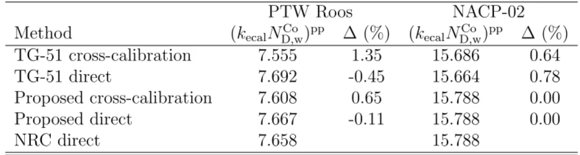
The reference depth, where chambers are positioned for reference dosimetry measurements,
233
is determined from dref = 0.6R50−0.1 cm. Chambers employed are:
234
Cylindrical Farmer-type - NE2571 and PTW30013. These are used in beams with all
ener-235
gies except 4 MeV - with the horizontal geometry employed it was not possible to position
236
these at the reference depth in the 4 MeV beam.
237
Cylindrical scanning-type - IBA CC13 and Exradin A1SL. The CC13 was used in beams
238
with all energies. The A1SL was used in a subset of beams (4 MeV and 8 MeV, 18 MeV
239
and 22 MeV but only using the 20×20 cm2 applicator).
240
Parallel-plate - Scanditronix NACP-02 and PTW Roos. These are used in beams with all
241
energies.
242
Cylindrical chambers are positioned with their central axis at dref. Gradient correction
fac-243
tors, for use with TG-51, are determined with equation4by also making measurements after
244
shifting the chamber axis by 0.5rcav downstream from the source. Parallel-plate chambers
245
are positioned with their effective point of measurement (EPOM) at dref. For the NACP-02,
246
measurements are performed with the EPOM taken to be 1.12 mm (the standard EPOM
247
used at NRC31 and that recommended by Muir and Rogers18) and 0.60 mm (the physical 248
thickness of the front window, which is that recommended by TG-51). For the PTW Roos
249
chamber, the EPOM is taken as 1.26 mm, which is the standard EPOM used at NRC31 for 250
this chamber and is the same as that used by scaling the front window of the chamber for
251
water equivalence.
252
The irradiation procedure uses a 10 Gy preirradiation to ensure that the chambers have
sta-253
bilized followed by a set of at least 5 readings acquired during 200 MU irradiations (≈2 Gy).
254
If it appears that there is a trend to the readings, readings are repeated until no trending
255
is observed. Measurements are made for all chambers at a given energy, with measurements
256
repeated with the first chamber at the end of a set of measurements to investigate linac drift
257
and repeatability of the results. In addition, two field monitor chambers are mounted on
258
the inside of the applicator such that they do not affect the collimated beam at the
phan-259
tom. These are also used during depth-ionization and reference dosimetry measurements to
260
track any drift in linac output and/or energy (a drift in the ratio of these monitor chamber
261
readings is indicative of a drift in energy and/or beam position drift).
262
Accepted
Article
Raw ionization chamber readings, Mraw, are corrected using
263
M = MrawPTPPionPpolPelecPleakPrp (7)
264
where:
265
PTP is the correction to standard environmental conditions of temperature and pressure. It
266
is obtained with the equation given in TG-51.
267
Pion is the ion recombination correction factor. It is obtained using the ion recombination
268
correction factors parameterized as a function of dose-per-pulse as in previous work13,29 269
where a comparison was also made to other publications.
270
Ppol is the correction for polarity effects. It is obtained by taking measurements using
volt-271
ages of opposite polarities with each chamber for each energy. Preirradiation of the chambers
272
is performed each time the polarizing voltage is changed before taking measurements.
273
Pelec is the electrometer correction factor. It was measured at the time the electrometers
274
used for this work were calibrated traceable to primary electrical standards (via a calibrated
275
voltage source and calibrated capacitors).
276
Pleak is the leakage correction factor. After irradiation, leakage current is collected for at
277
least the amount of time required for irradiation. In this work, leakage always contributes
278
to less than 0.05 % of the signal acquired during irradation so no correction for leakage is
279
applied.
280
Prp is the radial profile correction factor introduced by the addendum to TG-51 for photon
281
beams4 to correct for beam non-uniformity over the chambers’ central volume. It is acquired 282
using high-resolution 2-dimensional scans with a PTW microDiamond over the region
cov-283
ering the chambers’ active volume. For all chambers and all beam energies the correction
284
for beam non-uniformity is less than 0.15 %. The application of this correction factor here
285
is potentially confusing because it accounts for variation of the properties of the electron
286
beam unlike the other corrections that account for the non-ideal behavior of the ionization
287
chamber. It is kept in equation 7 to maintain consistency with the addendum to TG-51 for
288
MV photon beams.4 289
With these measurements, we derive dose per monitor unit (D/MU) three ways:
290
1. The TG-51 protocol for electron beam reference dosimetry is followed strictly (see
291
section I.A.), except that the updated kecal factor for the NACP-02 chamber from
292
Accepted
Article
Mainegra-Hing et al.34 is used here because data are not available in TG-51 for this 293
chamber type. This approach uses the formalism of TG-51 (equation 2), the data
294
for kecal and k′R50 from TG-51, a measured gradient correction factor for cylindrical 295
chambers (equation 4) and cross-calibration of parallel-plate chambers is performed
296
against cylindrical chambers in 18 MeV and 22 MeV beams. Data for k′
R50 for Farmer-297
type chambers and parallel-plate chambers use the fits given in TG-51 (equations 19
298
and 20 in that report). For the 4 MeV beam, the fit to k′
R50 for parallel-plate chambers 299
is still used to extrapolate to R50 =1.81 cm even though the fit is only valid to R50
300
=2 cm; this is the only way that data can be obtained from TG-51 for this low-energy
301
beam. The difference in k′
R50 for R50=1.81 cm and R50=2 cm is only 0.3 % so the use of 302
this extrapolation will not significantly impact the results. Data for the scanning-type
303
chambers are extracted from figure 5 in TG-51 for the chambers that are most similar
304
to the IBA CC13 and Exradin A1SL, which are the Wellhofer IC-10 and Exradin A1,
305
respectively. The beam quality conversion factors used for this method of analysis are
306
provided in table1. Parallel-plate chambers are used both ways allowed in TG-51 in all
307
beam energies (directly calibrated in cobalt-60 and the preferred method where they
308
are cross-calibrated in high-energy beams). Cylindrical chambers (directly calibrated
309
in cobalt-60) are used for all beams except the 4 MeV beam since this is not allowed
310
by TG-51.
311
2. The formalism laid out in section I.B. is followed. Cylindrical chambers are positioned
312
with the chamber axis at the reference depth and no gradient correction factor is
ap-313
plied because they are implicitly included in Monte Carlo calculations of beam quality
314
conversion factors. Parallel-plate chambers are used in all beams either directly using a
315
cobalt-60 calibration or with the modified cross-calibration procedure described above.
316
The data from Muir and Rogers18 are used, extracted from the tables in that work 317
for kQ,ecal and using the fits given in that work to determine k′Q with the measured
318
values of R50. The beam quality conversion factors used for this method of analysis are
319
provided in table 2. Data for all chambers employed here are provided in that work.
320
Extrapolation is not required for the 4 MeV beam since Muir and Rogers included
321
beams with R50 as low as 1.69 cm.
322
Although it is tempting to also perform the analysis with updated k′
R50 values and using 323
a measured gradient correction factor for cylindrical chambers, it is difficult because one
324
Accepted
Article
must extract the gradient correction factor from the Monte Carlo calculated k′
Qfactors,
325
which include gradient effects by definition. Muir and Rogers17 showed that there is 326
unacceptable scatter (RMSD=0.38 %) in the resulting k′
R50 factors when the shift of 327
0.5rcav is used to determine and extract the gradient correction factor. The same is
328
true when a shift of 0.5rcav of the chamber axis by 0.5rcav downstream from the source,
329
as required by the IAEA TRS-398,2 is employed. Muir and Rogers17 showed that 330
when considering results for clinical beams and including gradient effects by definition,
331
the scatter of k′
Q as a function of R50 is acceptable (RMSD=0.15 %), indicating that,
332
although the gradient correction factor can potentially vary from machine to machine,
333
including it for clinical beams in Monte Carlo calculated k′
Q factors yields acceptable
334
results.
335
3. Chambers calibrated directly against NRC primary standards for absorbed dose in
336
electron beams are used to obtain dose with
337
Dw = M ND,wQ , (8)
338
where ND,wQ is the calibration coefficient for the chamber in the beam of interest. NRC
339
primary standards for absorbed dose are described elsewhere6,22and are in good agree-340
ment with other primary standards dosimetry laboratories.7,35 Three of the chambers 341
used in this investigation (the NACP-02, the PTW Roos and the NE2571) have been
342
calibrated directly against NRC primary standards. This method is considered to be
343
the benchmark in this work for comparing the first two methods.
344
The reference for comparison is the result from the electron beam primary standard and so
345
the difference from this value, along with consistency between chambers, that is of interest.
346
III.
Results
347
The main results of this work are in figures1and2. Figure1(a) shows an average of results
348
for dose per monitor unit obtained using different chamber types using the recommendations
349
of TG-51. Results obtained using the two methods allowed by TG-51 are shown. The results
350
labelled “cross-calibration” use the methods recommended by TG-51. In this case,
parallel-351
plate chambers are cross-calibrated against cylindrical chambers in the 22 MeV beams (more
352
Accepted
Article
details on the results for (kecalND,wCo )ppare discussed below). For the 4 MeV beam, only results
353
using parallel-plate chambers are considered. For the 8 MeV and 12 MeV beams, results
354
obtained with all chambers are considered using cylindrical chambers calibrated in
cobalt-355
60 and cross-calibrated parallel-plate chambers. For the 18 MeV and 22 MeV beams, only
356
results obtained with cylindrical chambers are considered (since a cross-calibrated
parallel-357
plate chamber would produce redundant results). The results labelled “direct” use the other
358
approach allowed, but not recommended by TG-51, where all chambers are calibrated
di-359
rectly in cobalt-60. Again, for the 4 MeV beam, only the results obtained with the two
360
parallel-plate chambers are considered. The error bars demonstrate the variability of results
361
obtained using different chambers rather than the conventional method of conveying
uncer-362
tainties. This is done to provide a concise visual demonstration of the consistency (or lack
363
thereof) of results obtained using different chamber types. For the 4 MeV beam, the error
364
bars reflect the difference in results obtained using the two parallel-plate chambers; since
365
there are only two results the difference between them is relevant rather than the standard
366
deviation. For all other points, the error bars are the standard deviation of results using
367
different chambers. The results labelled “NRC” use chambers calibrated directly against
368
NRC primary standards for electron beam dosimetry. Figure 1 (b) shows an average of
369
results for dose per monitor unit obtained using different chamber types using the formalism
370
proposed in this work. In this case, the points labelled “cross-calibration” are an average
371
of results for plane-parallel chambers cross-calibrated against cylindrical chambers in
high-372
energy beams using the modified cross-calibration procedure described above and directly
373
calibrated cylindrical chambers. The points labelled “direct” use results obtained using all
374
chambers directly calibrated in cobalt-60. The error bars on all points reflect the
variabil-375
ity of the results obtained using different chamber types and in all cases are the standard
376
deviation of the results.
377
Figure 2 is the same as figure 1, except that the results are obtained in the 18 MeV
378
and 22 MeV beams shaped with the 20×20 cm2 applicator. For figure 2 (a), all results use
379
chambers calibrated directly in cobalt-60. Results are shown for only cylindrical chambers (as
380
is implied to be recommended by TG-51) or with all chambers (including directly calibrated
381
parallel plate chambers). Figure 2 (b) shows results obtained for all chambers using the
382
proposed method. Again, in both plots the results are compared to chambers calibrated
383
directly against primary standard for absorbed dose and the error bars are the standard
384
Accepted
Article
deviation of results obtained using different chamber types and so reflect the variability or
385
consistency results among chambers.
386
Although it is not shown in figures 1 or2, except for the 4 MeV beam following the
TG-387
51 approach (because only the results for the two parallel-plate chambers are applicable),
388
the difference between the maximum and minimum values for D/MU using different
cham-389
ber types is approximately 1 % following TG-51 recommendations (using cross-calibrated
390
parallel-plate chambers for low-energy beams and using only cylindrical chambers for
high-391
energy beams) and 2 % using all chambers directly calibrated in cobalt-60. The difference
392
in the maximum and minimum values for D/MU using different chamber types following
393
the proposed approach with updated data is approximately 1 % using either chambers
di-394
rectly calibrated in cobalt-60 or when parallel-plate chambers are cross-calibrated and used
395
in low-energy beams.
396
Table3compares the results using the different methods described in this work compared to
397
those obtained using NRC reference-class chambers directly calibrated against NRC primary
398
standards in electron beams. This comparison uses the same results as in figures 1 and 2 399
described above.
400
In the above, when cross-calibration is performed for parallel-plate chambers and then
401
used to derive D/MU, the value of (kecalND,wCo)pp uses results obtained in the 22 MeV with
402
the 20×20 cm2 applicator. Cross-calibration is against the reference NE2571 Farmer-type
403
chamber. Comparing results obtained in any of the other high-energy beams (18 MeV or
404
22 MeV, 10×10 cm2 applicator or 20×20 cm2 applicator) using the same method (TG-51 or
405
proposed) gives results that are consistent within 0.2 %. However, table 4 shows that the
406
different methods produce different results for (kecalND,wCo )pp. The three values in table 4for
407
the NACP-02 chamber obtained with the proposed formalism and either cross-calibration or
408
direct calibration and using primary standard for absorbed dose are identical, which seems
409
strange but is coincidental (the results in the table are identical from rounding to three
410
decimal digits, not a transcription error).
411
For this work, all chambers were calibrated in a cobalt-60 reference field within a few
412
weeks of the electron beam measurements. The cobalt-60 calibration coefficients for the two
413
Farmer-type chambers are in excellent agreement within 0.1 % compared to their historical
414
values. This is not surprising as these are laboratory-maintained reference-class chambers
415
Accepted
Article
that are regularly monitored and known to be stable. The two scanning type chambers have
416
very little calibration history in cobalt-60. The A1SL has been calibrated twice previously,
417
once in 2008 and once in 2014. These results (obtained in January 2019) are within 0.2 %
418
and 0.35 % of the values obtained in 2014 and 2008, respectively. Although these drifts are
419
larger than usually seen for Farmer-type chambers, this level of agreement is consistent with
420
the specifications for a reference-class chamber.4 Similarly, the CC13 calibration coefficient 421
was only calibrated once previously in 2008. The value obtained for this work is within 0.4 %
422
of that historical value. The parallel-plate chambers exhibited slightly worse stability than
423
the scanning type chambers. For the PTW Roos, the value obtained in January 2019 was
424
0.3 % and 0.6 % different from results obtained in 2011 and 2010, respectively. Similarly, for
425
the NACP-02, these results are 0.6 % and 0.7 % different from results obtained in 2011 and
426
2010, respectively. The stability of these parallel-plate chambers has also been monitored in
427
electron beams in the intervening years with a level of stability at about the 0.25 % level.
428
This level of stability is consistent with the results observed by Bass et al.21 for a large 429
sample of chambers.
430
IV.
Discussion
431
Figure 1 (a) shows that the standard deviation of results using different chambers when
432
TG-51 is followed strictly is on the order of 0.4 % when parallel-plate chambers are
cross-433
calibrated against cylindrical chambers. This is the approach recommended in TG-51 and
434
clearly produces more consistent results using parallel-plate chambers. In the 4 MeV beams,
435
the difference between the two plate chambers is only 0.25 %. If, however,
parallel-436
plate chambers are directly calibrated in a cobalt-60 beam (which is allowed by TG-51
437
but not recommended), the difference between results for these chambers is up to 2.2 %
438
in the 4 MeV beam. This is caused by the large difference between (kecalND,wCo)pp for the
439
PTW Roos chamber (see table 4). This difference is also the reason why the standard
440
deviation of results is larger for all other points when direct calibration is employed. The
441
same situation is apparent in figure2(a). Table 3 shows that the difference between results
442
that follow TG-51 and those obtained with chambers calibrated directly against primary
443
standard measurements are on the order of 0.6 % except for the 4 MeV beam where the
444
difference is 2.8 %.
445
Accepted
Article
Figure1(b) shows that when the proposed formalism and updated data are used standard
446
deviation using different chambers is on the order of 0.4 %, similar to that in figure 1 (a)
447
when cross-calibration is employed. The results and standard deviation are very similar
448
when parallel-plate chambers are directly calibrated in cobalt-60 or cross-calibrated against
449
cylindrical chambers in the 22 MeV beam. Table3shows that the agreement between these
450
results and those obtained with chambers calibrated directly against primary standards for
451
absorbed dose are on the order of 0.4 % with a maximum difference of 1.0 % in the 4 MeV
452
beam. This level of agreement is slightly better than when TG-51 is followed for higher energy
453
beams but using the proposed approach really improves the comparison in the lowest energy
454
(4 MeV) beam. Figure2(b) shows a similar level of consistenty (standard deviation≈0.4 %)
455
among results obtained using different chamber types when the 20×20 cm2 applicator is
456
used. Figure 2 and table 3 demonstrate excellent agreement using the proposed method
457
compared to results obtained with chambers calibrated directly against primary standard
458
measurements in high-energy beams shaped with the 20×20 cm2 applicator, better than that
459
when TG-51 is followed.
460
Table 4 shows that there is better agreement between (kecalND,wCo)pp with the primary
461
standard measurements when the direct approach, not recommended in TG-51, is used
462
compared to the values obtained when the cross-calibration procedure is employed for the
463
PTW Roos chamber. This improvement is likely only fortuitous but explains the better
464
agreement with primary standard measurements observed in table3with the direct approach,
465
especially for the 4 MeV beam where only the IBA NACP-02 and PTW Roos chambers can
466
be used following TG-51.
467
Table 4 demonstrates better consistency compared to the use of TG-51 between
468
(kecalND,wCo)ppresults obtained using the proposed method if parallel-plate chambers are
cross-469
calibrated or used directly. It also shows that they are in better agreement with those
ob-470
tained with primary standard measurements. This suggests a higher level of accuracy for
471
results obtained using the proposed formalism.
472
There is some difficulty drawing conclusions about the consistency of results obtained
473
using different chamber types when data for beam quality conversion factors from TG-51
474
are used to derive D/MU because TG-51 calculations of beam quality conversion factors
475
for chambers of the same type used the same assumptions and much of the same data for
476
Accepted
Article
individual correction factors. Therefore, the consistency between results might be misleading.
477
Conversely, the results for beam quality conversion factors used in the proposed formalism
478
are from independent Monte Carlo calculations using different geometrical chamber models
479
and materials. So although there are some correlations (e.g., the use of the same Monte
480
Carlo code system for all calculations) the results obtained using different chambers with
481
the proposed formalism are more independent than those that use data from the TG-51
482
protocol. Therefore, the level of consistency obtained using the proposed formalism is not
483
fortuitous.
484
The 5 % difference observed in figures 1 and 2 between the results for D/MU obtained
485
with the 10×10 cm2 applicator and the 20×20 cm2 applicator was investigated with
follow-486
on Monte Carlo simulations using BEAMnrc. The increased dose for the 10×10 cm2 field
487
size is caused by electrons scattering from the photon jaws and applicator that contribute
488
to dose at the reference depth. That R50 is only slightly impacted on the order of 1 mm by
489
this effect indicates that the magnitude of the effect is similar at dmax and at deeper depths
490
(i.e., R50).
491
There is very little difference in the consistency and accuracy of any of the results obtained
492
using the 20×20 cm2 field size or in R
50(see table1) compared to using the 10×10 cm2 field
493
size. This observation suggests that a revised protocol can also be simplified by making all
494
reference dosimetry measurements with a 10×10 cm2 field size.
495
These results point to questionable stability of parallel-plate chambers and this was also
496
noted in previous publications.6,13,20,21,36. This behavior implies that a method of stability 497
monitoring is required if parallel-plate chambers are to be used with a direct cobalt-60
498
calibration or that they be cross-calibrated against stable cylindrical chambers at the time
499
reference dosimetry measurements are made. Of course, best practice (and a requirement in
500
TG-51) is that secondary checks of reference dosimetry equipment be made for all chambers.
501
Although there is limited improvement in terms of accuracy in results obtained using
502
the proposed formalism over those obtained with TG-51, there are practical improvements
503
using the new approach. A simplified procedure has advantages in terms of robustness,
504
can help reduce clinical workload and reduce errors in the clinic. In addition, allowing the
505
use of more chamber types in all electron beams (i.e., reference-class cylindrical chambers
506
that have well-established behavior in photon beams) opens up the possibility for making
507
Accepted
Article
reference dosimetry measurements with more redundant systems. We intend to test the
508
proposed formalism in clinical settings in the near future to get feedback from multiple
509
users.
510
V.
Conclusions
511
A formalism is presented that is simplified compared to the AAPM TG-51 used by clinical
512
medical physicists in North America. It allows the use of calibrated cylindrical ionization
513
chambers in all electron beams (even those with low beam energies) and does not require
514
a measured gradient correction factor. In addition, more accurate data for beam quality
515
conversion factors are available for use with an updated formalism. The proposed formalism
516
is tested and compared to the present formalism and using data available in the AAPM
517
TG-51 protocol. The results also indicate that all electron beam reference dosimetry
mea-518
surements can be made in a 10×10 cm2 field, which would simplify the calibration procedure
519
and eliminate the need for multiple set-ups.
520
The use of the proposed formalism and updated data for beam quality conversion factors
521
improves the consistency of results obtained with different chamber types and improves the
522
accuracy of reference dosimetry measurements.
523
It is conceivable that a simplified formalism for reference dosimetry will reduce clinical
524
workload and reduce errors in reference dosimetry measurements due to misinterpretation. In
525
addition, allowing the use of more chamber types (i.e., cylindrical reference-class chambers)
526
introduces the potential for more redundant systems.
527
VI.
Acknowledgements
528
The author is grateful to Malcolm McEwen for useful discussions and comments on drafts of
529
this paper as well as James Renaud for help making the measurements and useful discussions.
530
VII.
Disclosure of Conflicts of Interest
531
The author has no conflicts of interest to disclose.
532
Accepted
Article
References
533 534
1 P. R. Almond, P. J. Biggs, B. M. Coursey, W. F. Hanson, M. S. Huq, R. Nath, and
535
D. W. O. Rogers, AAPM’s TG–51 protocol for clinical reference dosimetry of
high-536
energy photon and electron beams, Med. Phys. 26, 1847 – 1870 (1999).
537
2 IAEA, Absorbed Dose Determination in External Beam Radiotherapy: An International
538
Code of Practice for Dosimetry Based on Standards of Absorbed Dose to Water, volume
539
398 of Technical Report Series, IAEA, Vienna, 2001.
540
3 D. I. Thwaites, A. R. DuSautoy, T. Jordan, M. R. McEwen, A. Nisbet, A. E. Nahum, and
541
W. G. Pitchford, The IPEMB code of practice for electron dosimetry for radiotherapy
542
beams of initial energy from 4 to 25 MeV based on an absorbed dose to water calibration,
543
Phys. Med. Biol. 48, 2929 – 2970 (2003).
544
4 M. R. McEwen, L. A. DeWerd, G. S. Ibbott, D. S. Followill, D. W. O. Rogers, S. M.
545
Seltzer, and J. P. Seuntjens, Addendum to the AAPM’s TG–51 protocol for clinical
546
reference dosimetry of high-energy photon beams, Med. Phys. 41, 041501(20pp) (2014).
547
5 G. Stucki and S. V¨or¨os, Experimental k
Q,Q0 Electron Beam Quality Correction
548
Factors for the Types NACP02 and PTW34001 Plane-parallel Chambers, Proceed. 549
of Absorbed Dose and Air Kerma Primary Standards Workshop, LNHB, Paris ,
550
http://www.nucleide.org/ADAKPS WS/ (May, 2007).
551
6 B. R. Muir, C. D. Cojocaru, M. R. McEwen, and C. K. Ross, Electron beam water
552
calorimetry measurements to obtain beam quality conversion factors, Med. Phys. 44,
553
5433–5444 (2017).
554
7 A. Krauss and R. Kapsch, Direct determination of k Q factors for cylindrical and
plane-555
parallel ionization chambers in high-energy electron beams from 6 MeV to 20 MeV,
556
Phys. Med. Biol. 63, 035041 (2018).
557
8 A. Kosunen, H. J¨arvinen, and P. Sipil¨a, Optimum calibration of NACP type
plane-558
parallel ionization chambers for absorbed dose determinations in low energy electron
559
beams, in Proc. of Symp. on Meas. Assurance in Dosimetry, pages 505 – 513, IAEA–
560
SM–330/419, IAEA, Vienna, 1994.
561
Accepted
Article
9 G. Christ, O. S. Dohm, G. Bruggmoser, and E. Sch¨ule, The use of plane-parallel
cham-562
bers in electron dosimetry without any cross-calibration, Phys. Med. Biol. 47, N121 –
563
N126 (2002).
564
10 A. Palm, L. Czap, P. Andreo, and O. Mattsson, Performance analysis and determination
565
of the pwall correction factor for60Co γ-ray beams for Wellh¨ofer Roos-type plane-parallel
566
chambers, Phys. Med. Biol. 47, 631 – 640 (2002).
567
11 M. R. McEwen, S. Duane, and R. A. S. Thomas, Absorbed dose calibration factors
568
for parallel-plate chambers in high energy photon beams, in Standards and Codes of
569
Practice in Medical Radiation Dosimetry; Proc. Int’l Symp, Vienna 25 – 28 Nov 2002,
570
volume 1, pages 335 – 341, IAEA, Vienna, 2003.
571
12 R. P. Kapsch, G. Bruggmoser, G. Christ, O. S. Dohm, G. H. Hartmann, and E. Sch¨ule,
572
Experimental determination of pCo perturbation factors for plane-parallel chambers,
573
Phys. Med. Biol. 52, 7167 – 7181 (2007).
574
13 B. R. Muir, M. R. McEwen, and D. W. O. Rogers, Beam quality conversion factors for
575
parallel-plate ionization chambers in MV photon beams, Med. Phys. 39, 1618 – 1631
576
(2012).
577
14 R. P. Kapsch and I. Gomola, Beam quality correction factors for plane parallel
cham-578
bers in photon beams , IAEA–E2-CN-182, Book of Extended Synopses for Symp. on
579
Standards, Applications and Quality Assurance in Medical Radiation Dosimetry (IAEA,
580
Vienna) , 35 – 36 (2010).
581
15 Radiological Physics Center, TG-51: Common errors and helpful hints., http://rpc.
582
mdanderson.org/RPC/Newsletter/Volume%203/Volume%203-Issue%207.pdf,
Ac-583
cessed: 2019-09-26.
584
16 B. R. Muir and M. R. McEwen, On the use of cylindrical ionization chambers for electron
585
beam reference dosimetry, Med. Phys. 44, 6641–6646 (2017).
586
17 B. R. Muir and D. W. O. Rogers, Monte Carlo calculations for reference dosimetry of
587
electron beams with the PTW Roos and NE2571 ion chambers, Med. Phys. 40, 121722
588
(16pp) (2013).
589
Accepted
Article
18 B. R. Muir and D. W. O. Rogers, Monte Carlo calculations of electron beam quality
590
conversion factors for several ion chamber types, Med. Phys. 41, 111701 (15pp) (2014).
591
19 I. Kawrakow, E. Mainegra-Hing, D. W. O. Rogers, F. Tessier, and B. R. B. Walters,
592
The EGSnrc Code System: Monte Carlo simulation of electron and photon transport,
593
NRC Technical Report PIRS-701 v4-2-3-2, National Research Council Canada, Ottawa,
594
Canada. http://www.irs.inms.nrc.ca/inms/irs/EGSnrc/EGSnrc.html, 2011.
595
20 B. Muir, Ion chamber absorbed dose calibration coefficients, N
D,w, measured at ADCLs:
596
Distribution analysis and stability, Med. Phys. 42, 1546–1554 (2015).
597
21 G. Bass, R. Thomas, and J. Pearce, The calibration of parallel-plate electron ionization
598
chambers at NPL for use with the IPEM 2003 code of practice: summary data, Phys.
599
Med. Biol. 54, N115 – N124 (2009).
600
22 C. Cojocaru, G. Stucki, M. McEwen, and C. Ross, Determination of absorbed dose to
601
water in megavoltage electron beams using a calorimeter-Fricke hybrid system , IAEA–
602
E2-CN-182, Book of Extended Synopses for Symp. on Standards, Applications and
Qual-603
ity Assurance in Medical Radiation Dosimetry (IAEA, Vienna) , 27 – 28 (2010).
604
23 M. R. McEwen, A. J. Williams, and A. R. DuSautoy, Determination of absorbed dose
605
calibration factors for therapy level electron beam ionization chambers, Phys. Med. Biol.
606
46, 741 – 755 (2001).
607
24 M. R. McEwen and A. R. DuSautoy, Primary standards of absorbed dose for electron
608
beams, Metrologia 46, S59–S79 (2009).
609
25 J. Sempau, P. Andreo, J. Aldana, J. Mazurier, and F. Salvat, Electron beam quality
610
correction factors for plane-parallel ionization chambers: Monte Carlo calculations using
611
the PENELOPE system, Phys. Med. Biol. 49, 4427 – 4444 (2004).
612
26 K. Zink and J. Wulff, Beam quality corrections for parallel-plate ion chambers in electron
613
reference dosimetry, Phys. Med. Biol. 57, 1831–1854 (2012).
614
27 F. Araki, Monte Carlo calculations of correction factors for plane-parallel ionization
615
chambers in clinical electron dosimetry, Med. Phys. 35, 4033 – 4040 (2008).
616
Accepted
Article
28 J. Renaud, A. Sarfehnia, K. Marchant, M. McEwen, C. Ross, and J. Seuntjens, Direct
617
measurement of electron beam quality conversion factors using water calorimetry, Med
618
Phys 42, 6357 (2015).
619
29 M. R. McEwen, Measurement of ionization chamber absorbed dose k
Q factors in
mega-620
voltage photon beams, Med. Phys. 37, 2179 – 2193 (2010).
621
30 M. R. McEwen, I. Kawrakow, and C. K. Ross, The effective point of measurement of
622
ionization chambers and the build-up anomaly in MV x-ray beams, Med. Phys. 35, 950
623
– 958 (2008).
624
31 F. Lacroix, M. Guillot, M. McEwen, C. Cojocaru, L. Gingras, A. S. Beddar, and
625
L. Beaulieu, Extraction of depth-dependent perturbation factors for parallel-plate
cham-626
bers in electron beams using a plastic scintillation detector, Med. Phys. 37, 4331 – 4342
627
(2010).
628
32 L. L. W. Wang and D. W. O. Rogers, Study of the effective point of measurement for
629
ion chambers in electron beams by Monte Carlo simulation, Med. Phys. 36, 2034 – 2042
630
(2009).
631
33 K. Zink and J. Wulff, On the wall perturbation correction for a parallel-plate NACP-02
632
chamber in clinical electron beams, Med. Phys. 38, 1045 – 1054 (2011).
633
34 E. Mainegra-Hing, I. Kawrakow, and D. W. O. Rogers, Calculations for plane-parallel
634
ion chambers in 60Co beams using the EGSnrc Monte Carlo code, Med. Phys. 30, 179
635
– 189 (2003).
636
35 M. McEwen, P. Sharpe, and S. V¨or¨os, Evaluation of alanine as a reference dosimeter
637
for therapy level dose comparisons in megavoltage electron beams, Metrologia 52, 272
638
(2015).
639
36 A. Palm, O. Mattsson, and P. Andreo, Calibration of plane-parallel chambers and
640
determination of pwall for the NACP and Roos chambers for 60Co γ-ray beams, Phys.
641
Med. Biol. 45, 971 – 981 (2000).
642
Accepted
Article
VIII.
Figures and tables
643
Table 1: The nominal energies of the electron beams and beam quality specifiers (the depth where the absorbed dose falls to 50 % of its maximum value, R50), used in this work. The
beam quality conversion factors used to follow the TG-51 approach, as described in the text, are provided for each chamber type.
Beam k′
R50
Nominal
R50 (cm) NE2571 30013 CC13 A1SL NACP-02 Roos
energy (MeV) 10×10 cm2 applicator 4 1.81 - - - - 1.059 1.059 8 3.23 1.020 1.020 1.018 1.024 1.038 1.038 12 4.71 1.010 1.010 1.009 - 1.022 1.022 18 7.05 1.001 1.001 1.001 - 1.004 1.004 22 8.69 0.997 0.997 0.996 - 0.994 0.994 20×20 cm2 applicator 18 7.10 1.001 1.001 1.001 1.002 1.003 1.003 22 8.80 0.997 0.997 0.996 0.995 0.993 0.993 kecal Qecal 7.50 0.903 0.897 0.904 0.915 0.885 0.901
Table 2: The nominal energies of the electron beams and beam quality specifiers (the depth where the absorbed dose falls to 50 % of its maximum value, R50), used in this work. The
beam quality conversion factors used to follow the updated approach, as described in the text, are provided for each chamber type.
Beam k′
Q
Nominal
R50 (cm) NE2571 30013 CC13 A1SL NACP-02 Roos
energy (MeV) 10×10 cm2 applicator 4 1.81 - - 1.036 1.041 1.064 1.064 8 3.23 1.023 1.022 1.020 1.024 1.037 1.037 12 4.71 1.011 1.010 1.010 1.018 1.019 18 7.05 1.002 1.002 1.001 - 1.002 1.002 22 8.69 0.998 0.998 0.997 - 0.995 0.995 20×20 cm2 applicator 18 7.10 1.002 1.001 1.001 1.001 1.002 1.002 22 8.80 0.998 0.998 0.997 0.995 0.995 0.995 kQ,ecal Qecal 7.50 0.903 0.901 0.904 0.914 0.892 0.898
Accepted
Article
Figure 1: The results for dose/MU determined using different methods using the 10×10 cm2
applicator as a function of R50. The data are offset slightly along the x-axis for clarity. The
errors bars are the standard deviation of results obtained using different chambers. For the lowest energy points in panel (a), the error bars reflect the difference between the results obtained using the two parallel-plate chambers. Panel (a) uses the approaches in TG-51 while panel (b) uses the formalism and data proposed in this work. More details on the different methods are described in the text. The same scale is used on both plots to make it easier to compare results. The data labelled “NRC” in both plots are identical.
Accepted
Article
Figure 2: As in figure 1 but using the 20×20 cm2 applicator. These results are for the
18 MeV and 22 MeV beams.
Accepted
Article
Table 3: Comparison of different methods to determine absorbed dose. The comparison is against method 3, where chambers are calibrated directly against primary standards for absorbed dose. The percent differences (given in columns 2, 3 and 4) are calculated as ∆ = xNRC−xmethod
xNRC .
Nominal TG-51 TG-51 Proposed
energy (MeV) recommended (%) direct (%) direct (%) 10×10 cm2 applicator 4 2.75 1.94 0.99 8 0.78 0.50 -0.43 12 0.18 -0.15 -0.83 18 0.70 0.46 -0.17 22 0.47 0.26 -0.58 20×20 cm2 applicator 18 0.91 0.63 0.06 22 0.53 0.31 -0.42
Table 4: Comparison of different methods of obtaining the parameter, (kecalND,wCo)pp. The
percent differences are calculated as ∆ = xNRC−xmethod
xNRC .
PTW Roos NACP-02
Method (kecalND,wCo)pp ∆ (%) (kecalND,wCo )pp ∆ (%)
TG-51 cross-calibration 7.555 1.35 15.686 0.64
TG-51 direct 7.692 -0.45 15.664 0.78
Proposed cross-calibration 7.608 0.65 15.788 0.00
Proposed direct 7.667 -0.11 15.788 0.00
NRC direct 7.658 15.788
Accepted
Article
IX.
Figure captions
644
Figure 1: The results for dose/MU determined using different methods using the 10×10 cm2
645
applicator as a function of R50. The data are offset slightly along the x-axis for clarity. The
646
errors bars are the standard deviation of results obtained using different chambers. For the
647
lowest energy points in panel (a), the error bars reflect the difference between the results
648
obtained using the two parallel-plate chambers. Panel (a) uses the approaches in TG-51
649
while panel (b) uses the formalism and data proposed in this work. More details on the
650
different methods are described in the text. The same scale is used on both plots to make it
651
easier to compare results. The data labelled “NRC” in both plots are identical.
652
Figure 2: As in figure 1 but using the 20×20 cm2 applicator. These results are for the
653
18 MeV and 22 MeV beams.
654