Design and Testing of a High Accuracy Robotic
Single-cell Manipulator
MASSACHUSETTS INSTITUTEbyr
by~~
JUL 2'3 j'
Jun Young Yoon
B.S., Mechanical Engineering, Yonsei University (2009)
ARCHIVES
Submitted to the Department of Mechanical Engineering
in partial fulfillment of the requirements for the degree of
Master of Science in Mechanical Engineering
at the
MASSACHUSETTS INSTITUTE OF TECHNOLOGY
June 2011
@
Massachusetts Institute of Technology 2011. All rights reserved.
I/1/
A uthor
... ...
dEfigineering
May 19, 2011
10% IfCertified by...
David L. Trumper
Professor of Mechanical Engineering
Thesis Supervisor
A ccepted by ... .. ... ...
David E. Hardt
Chairman, Department Committee on Graduate Students
Design and Testing of a High Accuracy Robotic Single-cell
Manipulator
by
Jun Young Yoon
Submitted to the Department of Mechanical Engineering on May 19, 2011, in partial fulfillment of the
requirements for the degree of
Master of Science in Mechanical Engineering
Abstract
We have designed, built and tested a high accuracy robotic single-cell manipulator to be able to pick individual cells from array of microwells, each 30 Pm or 50 pm cubed. Design efforts have been made for higher accuracy, higher throughput, and compactness. The proposed system is designed to have a T-drive mechanism with two linear stages for XY-plane positioning to have higher stiffness and less structurally inherent error. Precision is especially required in Z-axis movement for successful cell-retrieval procedure and so a rotational mechanism with a voice coil actuator, among many options, is selected for the Z-axis motion because this results in relatively smaller reaction on the system and has advantages of direct drive. The prototype of the robotic single-cell picker integrates the Z-axis and XY stage motion, real-time microscopy imaging, and cell manipulation with a NI PXI-controller centered as a main real-time controller. This prototype is built to test performances of the proposed system in terms of single-cell retrieval and this thesis also discusses the experiments for the cell-retrieval process with microbeads of the equivalent size and the results as well.
This proposed system will be used to help select and isolate an individual hy-bridoma from polyclonal mixture of cells producing various types of antibodies. It is important to be able to do this cell-retrieval task since a single isolated hybridoma cell produces monoclonal antibody that only recognizes specific antigens, and this monoclonal antibody can be used to develop cures and treatments for many dis-eases. Our research's development of accurate and dedicated mechatronics solution will contribute to more rapid and reliable investigation of cell properties. Such anal-ysis techniques will act as catalyst for quicker discovery of treatments and vaccines on a wide range of diseases including HIV infection, tuberculosis, hepatitis C, and malaria with potential impact on the society.
Thesis Supervisor: David L. Trumper Title: Professor of Mechanical Engineering
Acknowledgments
I would first like to thank my advisor, Professor David Trumper for his guidance and support. Professor David Trumper has been inspirational in every aspect, especially with his knowledge in mechanical, electrical, and interdisciplinary fields and with his teaching skills. Every meeting I had with him, I learned valuable lessons on new and interesting things. Also, whenever I talked to him, he led me to set the right direction for my research as well as my courses and his encouraging comments and advice have always been a strength for me to go on. Under his supervision past two years, I have learned much more than I would otherwise expect and I am thrilled to continue my PhD journey in his guidance.
I would also like to thank my labmates for their support and kindness. Aaron Gawlik was always willing to help and answer all my questions. He helped me adjust myself in the lab when I first began my research, and I am always grateful for the
support. Ian Mackenzie was also always voluntary to give me valuable advice. His vast knowledge on control was greatly beneficial to my curiosity. Talking to him was always pleasant and his kindness will never be forgotten. Darya Amin-Shahidi has also been a good friend for me and his willingness to help and support has always moved my mind. His expertise in Matlab and Simulink, especially, helped me figure out several issues on my research. From Mohammad Iman Nejad, I gained machine shop experience which helped me much to manufacture a number of parts for the research. His valuable advice based on the field experience was always inspiring and appreciated. I also give my thanks to our administrative assistant, Laura Zaganjori. She helped the lab run smoothly and her help was always timely.
My friends were also very helpful. Sangok Seok, dear friend and my Labview tutor, supported me with his great expertise in Labview. A number of troubles I had with Labview were eased by him and I greatly thank him for his assistance. Chargrak Choi has been my dearest friend ever since I arrived in the United States. He was always open to discussion and talking to him was always refreshing and eye-opening. I would also like to express my gratitude for dear friends, Kyoo-chul and Minseok
for their assistance in every aspect. I thank Lesley Yu from National Instruments for her generous donation of a real-time controller and Sepehr Kiani from Helicos for the donation of microscope stages and a syringe pump. I also thank Leslie Regan and Joan Kravit for their timely support and kindness.
Finally and gratefully, I would like to thank my wife and my little daughter with all my heart. Without my wife's support and faith, I would not be able to finish what I started. The devotion and sacrifice she made for me and the family is most appreciated with all my love. My daughter, Sarie has been a blessing and her existence itself always gives me the strength to carry on. Thank you, daughter.
Contents
1 Introduction
1.1 Motivation and Goal of the Research . . . . 1.2 Layout of the Thesis . . . .
2 Research Background
2.1 Cell-screening Process . . . .
2.1.1 Microengraving . . . .
2.2 Cell-retrieval Device...
2.2.1 Functions of the CellCelector .
2.2.2 Limitations . . . .
3 Design Concepts and Component Selection
3.1 Design Concepts . . . .
3.1.1 Design Options for the Cell Picker . . 3.1.2 Conceptual Configurations . . . . ..
3.2 Z-axis Mechanism Selection . . . ..
3.2.1 Mechanism Options . . . . 3.2.2 Actuator and Sensor . . . .
3.3 Microscope and Microscope Stage...
3.3.1 Desired Specifications . . . .
3.3.2 Inverse Microscope Design...
4 Mechanical Design and Implementation
21 21 22 . . . . 23 . . . . 23 . . . . 24 29 29 30 33 35 35 42 44 45 46
4.1 Prototype of the Single Cell Picker . . . . 49
4.2 Picking Method . . . . 51
4.2.1 Syringe Pump . . . . 51
4.2.2 Issues with Leakage . . . . 53
4.3 Z-axis Mechanism . . . . 58
4.3.1 Voice Coil Actuator . . . . 58
4.3.2 Optical Encoder . . . . 61
4.4 Self-designed Microscope . . . . 66
4.4.1 Self-designed Inverse Microscope . . . . 66
4.4.2 Microscope Stage with Piezo-actuator . . . . 69
5 System Integration and Control Design 71 5.1 System Integration . . . . 71
5.1.1 Scheme for the Prototype . . . . 72
5.2 PID Control for the XY Stage . . . . 73
5.3 Control Loop for the Z-axis Motion . . . . 78
5.3.1 Frequency Response of the Plant . . . . 79
5.3.2 Mass Disconnection . . . . 80
5.3.3 Amplitude-dependent Frequency Response . . . . 83
5.3.4 System Modeling by Fitting . . . . 88
5.4 Loop-shaping Controller Design . . . . 89
5.4.1 Lead Compensator . . . ... . . . 90
5.4.2 Lead-Lag Compensator . . . . 91
5.4.3 Trajectory Generation . . . . 94
5.5 System Performance . . . . 97
5.5.1 Time Response Analysis . . . . 97
6 Experiments, Results, and Challenges 103 6.1 Experiment Process . . . . 103
6.2 Results and Discussions . . . . 107
6.3 Challenges . . . . 108 8
6.3.1 Illum ination . . . . 108 6.3.2 Encoder Alignment and Calibration . . . . 109
7 Conclusion and Future Work 117
A Labview codes 121
A.1 Control panels for the syringe pump, microscope stage, and vision 121 A.2 FPGA edge counter for the A-quad-B encoder . . . ... 128 A.3 Real-time control loop . . . . 129
B Vendors 131
C Drawing 135
List of Figures
2-1 Microengraving technique: schematic diagram depicting method for
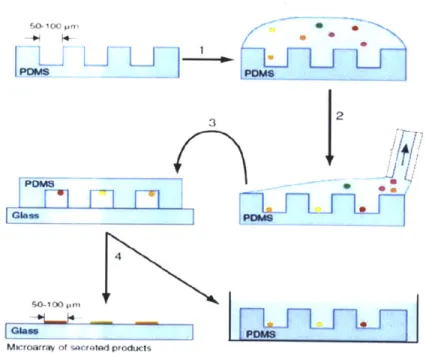
preparation of engraved arrays of secreted products from a mixture of cells. (1)A suspension of cells is deposited onto an array of microwells. (2)The cells are allowed to settle into the wells and then the excess medium is removed by aspiration. (3)The dewetted array is placed in contact with a pretreated solid support (glass slide), compressed lightly and incubated for 2-4h. (4)The microwells are removed from the solid support and placed in a reservoir of medium. (Illustrations
and captions taken from [2].) . . . .
22
2-2 Picture of the existing system, CellCelector. . . . . 24
2-3 Mechanism for the 3-DOF positioner of the CellCelector. . . . . 25
2-4 Small error in the first link causing large error at the end-effector. . . 25
3-1 One design option considered for the robotic single-cell manipulator. 31
3-2 Design of gantry configuration for the robotic single-cell manipulator. 32
3-3 Design of T-drive system for the robotic single-cell manipulator. . . 33
3-4 Conceptual configurations for the robotic single-cell manipulator. . 34
3-5 Linear mechanism options considered for the Z-axis motion. . . . . . 36
3-6 Rotational mechanism options considered for the Z-axis motion. . . . 37
3-7 More options for the Z-axis motion with four-bar linkage structure. . 38 3-8 Cantilever beams under the vertical reaction force and the reaction
torque. . . . . 39
3-10 Arm extension design for the voice coil actuator. . . . . 43
3-11 Assembled CAD model for the Z-axis actuator with arm extension. . 44 3-12 Components for the self-designed inverse microscope. . . . . 45
3-13 Assembled CAD model for the self-designed inverse microscope. . . . 46
4-1 Physical configurations of the prototype. . . . . 50
4-2 Partial configurations of the microscope and z-axis mechanism. ... 50
4-3 OEM syringe pump for the process of cell-retrievals. . . . . 52
4-4 User interface control panel for the syringe pump. . . . . 52
4-5 Cellcelector with its sealing components. . . . . 53
4-6 Schematic of how fittings work to seal the pipette module. . . . . 54
4-7 Sealing test setup with two different materials of tubing. . . . . 55
4-8 Sealing test with two different materials of tubing. . . . . 56
4-9 Implementing new tubing prototypes on the CellCelector. . . . . 57
4-10 Testing cell-retrievals with a new tubing prototype. . . . . 58
4-11 Actuation part of the old hard disk drive selected in the previous chapter. 59 4-12 Rotational z-axis mechanism with VCA and extended arm. . . . . 61
4-13 Selected mechatronics system for the z-axis motion. . . . . 62
4-14 Mounting position for an optical encoder. . . . . 62
4-15 Implementing an optical encoder on the selected mounting area. . . . 63
4-16 Alignment setting for the grating and the mounting hub and a magni-fied view of the grating patterns. . . . . 64
4-17 CAD assembly simulation for the encoder implementation. . . . . 65
4-18 Physical system with the encoder, gratings, and head implemented. . 65 4-19 Self-constructed inverse microscope on a granite table. . . . . 67
4-20 Testing of the self-constructed microscope. . . . . 68
4-21 User interface with Labview for the microscope system. . . . . 68
4-22 Piezoceramic actuator in the microscope stage. (Figures taken from [2 1].) . . . . 69
5-2 The software package, PMAC Pro2, for the UMAC controller. .... 74
5-3 Step response of the stage with the auto-tuned gains. . . . . 75
5-4 Step response of the stage with the fine-tuned gains . . . . 76
5-5 Step response of the stage with the reselected gains for faster rise time. 77
5-6 Control loop for Z-axis picking motion. . . . . 78 5-7 Setup for the frequency response measurement of the plant. . . . . 79 5-8 Measured frequency response of the plant. . . . . 80 5-9 Flexure body depicted as two masses connected with a spring and
dam per. . . . . 81
5-10 Simplified pole-zero maps of the collocated and non-collocated system. 82 5-11 Bode plots of two-mass model. . . . . 82 5-12 Amplitude-dependent frequency response of the arm system with
bear-ing. Upper curve is with 1 V drive amplitude; lower curve is with 0.3
V drive amplitude. . . . . 84
5-13 Friction torque versus relative velocity for large displacement [12]. . . 85
5-14 The friction interface between two surfaces is thought of as a contact between bristles. For simplicity the bristles on the lower part are shown
as being rigid. (Illustration and captions taken from [14].) . . . . 86
5-15 Bristle friction model for microscopic presliding displacement.
(Illus-tration taken from [14].) . . . .
87
5-16 Conceptual sketch of an amplitude-dependent frequency response. . . 87
5-17 Bode plot of the fitted model for the plant. . . . . 88 5-18 Bode plot of the experimental response and the analytical model with
lead compensator at w,=20 Hz. . . . . 90
5-19 Effect of T on the lead-lag compensator. . . . . 92 5-20 Effect of T on the loop transfer function. . . . . 93 5-21 Frequency response of the loop transfer function with the lead-lag
com-pensator. . . . . 94
5-22 Position, velocity, acceleration profile of the cubic polynomial. .... 95
5-24 Effect of T on the unit step response of the closed loop system. . . . 5-25 Error plot of step response of the closed loop system. . . . . 5-26 Measured time responses of the closed loop system. X axis is in clock
ticks of 50 ps. . . . . 5-27 Magnified portion of the beginning of the step response with a delay.
6-1 Bubbles trapped around microwells in hydrophilic and hydrophobic
states. . . . . 6-2 Tip of the picking module on the surface of PDMS microwells...
6-3 One block of PDMS microwells before and after the cell-retrieval with
the prototype. . . . .
6-4 Suggested position to place a ring illuminator. . . . .
6-5 Unexpected oscillation in the closed-loop time responses. . . . .
6-6 The strange oscillation occurred with double (2x) decoder. . . . . 6-7 A-quad-B encoder output signal when the oscillation occurs. . . . . . 6-8 No more strange oscillation after realignment and recalibration. . . . A-i Labview code for the syringe pump control panel...
A-2 First case structure in the syringe pump control loop. A-3 Second case structure in the syringe pump control loop. A-4 Detailed code for the Tecan subvi. . . . . A-5 Labview code for the microscope stage control panel. . . A-6 Case structure in the microscope stage control loop. . . . A-7 Labview code for the vision panel. . . . . A-8 Labview code for the encoder edge counter in FPGA. . . A-9 Labview code for the real-time controller. . . . . A-10 Detailed code for the Cubic subvi. . . . . C-1 Drawing for the mounting hub discussed in Chapter 4.
97 98 99 100 104 105 107 109 110 112 113 114 . . . . 122 . . . . 123 . . . . 123 . . . . 124 . . . . 125 . . . . 126 . . . . 127 . . . . 128 . . . . 129 . . . . 130 136
Chapter 1
Introduction
The focus of this thesis is to design and test a high accuracy robotic single-cell manip-ulator for cell-retrieving processes. We have designed and built a prototype single-cell picker which uses a rotary servomechanism together with a syringe and pipette to pick individual cells from mirowells. Our design has several advantages over an existing system, CellCelector detailed in Chapter2. First, the proposed system uses more compact and simpler design and is structurally less prone to error. Second, the
Z-axis, which is the most important part for accurate cell picks, is direct drive so that mechanical errors such as backlash as well as the overall positioning noise can be re-moved, resulting better precision. This research has been conducted over the last one and a half years in Precision Motion Control (PMC) Laboratory at the Massachusetts Institute of Technology (MIT) under the supervision of Professor David Trumper. In this chapter, we discuss the motivations for the research together with the goal of the project. We also provide the layout of the thesis in this chapter.
1.1
Motivation and Goal of the Research
As multidisciplinary research at the intersection of biology, chemistry, and engineer-ing is growengineer-ing, the need of engineerengineer-ing insights to the design of instrumentation and processes is also rapidly increasing. The cell-retrieving process is one of those exem-plary situations where engineering insights, especially machine design and precision
control, can make a significant difference.
The cell-retrieving/isolation process is very important in biochemistry, biomedical research, and medicine because certain single cells producing monoclonal antibodies can be utilized to find cures and treatments for many diseases. Usually this cell-isolating process comes after cell screening processes where we locate cells of interest among large group of various cells with different secretions. This cell screening process has been significantly improved by a novel technique called microengraving, which is a microwell-based soft lithography method to print and thereby assay secretions of individual cells in large numbers [2].
While the microengraving screening process has high throughput due to the novel technique, the cell-retrieval procedure is limited by the capabilities of a commercially available instrument. The commercial robotic manipulator called CellCelector is es-sentially less accurate with limited throughput due to the design and mechanism that limit the precision. These issues are detailed in Chapter 2. Accordingly, the main focus of our research is on developing a more reliable and more accurate system with simple and robust design so that the overall throughput for the process can be im-proved. The primary goal, therefore, is to design and construct a prototype for the proposed system and test it to see if individual cell can be successfully retrieved and if it is possible to eventually automate the critical steps to have higher throughput.
This research's development of precise and dedicated mechatronics solution is believed to contribute to more rapid and reliable investigation of cell properties. Such analysis techniques will act as catalyst for quicker discovery of treatments and vaccines on a wide range of diseases including HIV infection, tuberculosis, hepatitis C, and malaria with potential impact on the society.
1.2
Layout of the Thesis
We have introduced our research by explaining its motivation and goal in this chapter. The rest of the thesis is composed of six other chapters. Chapter 2 provides a brief background for the research by detailing the cell-screening process and the existing
device with its functions and limitations. Chapter 3 then details the design concepts and configurations for our proposed system, robotic single-cell manipulator, and de-scribes component selections. Chapter 4 shows the physical prototype system and details how each part is implemented. In Chapter 5, we explain how we integrate the overall system and how we design our controller to make the prototype ready for test. We then detail the experiments we conducted to test the system and also provide the results in Chapter 6. Finally, we finish the thesis by providing the conclusion and suggestions for the future work. In addition, associated Labview codes and compo-nent details together with other relevant information are provided in Appendices A, B, and C.
Chapter 2
Research Background
In this chapter, we discuss the background of our research and provide a context
of why this research is of importance. First we detail the technique called
microen-graving, a novel method of cell-screening developed by the Love Lab in the Chemical Engineering Department in MIT, whom we are jointly working with. We then dis-cuss the commercial system for cell retrieval that the Love Lab is currently using; specifications of this system are presented with its limitations.
2.1
Cell-screening Process
In order to understand the context of this research, we need to be familiar with a few biological concepts. A monoclonal antibody is an antibody produced by a single clone of hybridoma cells and only recognizes specific corresponding antigens. This is an important substance in biochemistry, biomedical research, and medicine because this antibody can be used to develop cures and treatments for many diseases. In order to extract a single monoclonal antibody, an individual hybridoma has to be selected from polyclonal mixture of cells producing various types of antibodies. The selection of a hybridoma requires two main tasks: screening of antibodies produced by large group of cells and retrieval of the specific cells with target antibodies [2].
For the screening process, a novel microwell-based technique, called
the following section.
2.1.1
Microengraving
Microengraving, is a soft lithography method to print secretions of individual cells using a dense array of microwells (0.1 to 1 nL each) containing single cells. In our current work, the wells are 50 pim cubed. The steps of this technique are illustrated in Figure 2-1 below.
I
LiL
3 2ij
Glass PCMS 4Microarray of %acroiad producis
Figure 2-1: Microengraving technique: schematic diagram depicting method for preparation of engraved arrays of secreted products from a mixture of cells. (1)A suspension of cells is deposited onto an array of microwells. (2)The cells are allowed to settle into the wells and then the excess medium is removed by aspiration. (3)The dewetted array is placed in contact with a pretreated solid support (glass slide), compressed lightly and incubated for 2-4h. (4)The microwells are removed from the solid support and placed in a reservoir of medium. (Illustrations and captions taken from [2].)
A polydimethylsiloxane (PDMS) stamp shown in the figure has arrays of microwell blocks and one block is composed of 7 x7 50 pum microwells or 12x12 30 pm microw-ells, allowing one PDMS stamp to contain 84,000 to 248,000 microwells. Unlike the existing serial-dilution process where dilution has to be repeated until monoclonality is acquired, this method allows assays of large number of living cells in parallel and so yields much higher unit assay screening throughput of more than 100,000 individual cells [2]. After the step 4 in the figure, the microarray of secreted products is printed on the glass slide corresponding to the locations of cells in the PDMS microwells, and this is why this technique is considered as a soft lithography. Since we can locate cells of interest in the PDMS stamp by comparing positions with the microarray on the slide, it is now important to be able to retrieve those cells individually.
2.2
Cell-retrieval Device
In the previous section, we learn that the microengraving technique enables high screening throughtput. However, in order to isolate a single cell for the further re-search, it is critical to have an accurate and high-throughput process of cell-retrieval. In this section, we introduce a commercial system that is currently used in the Love Lab for the cell picking. We then point out limitations of the system.
2.2.1
Functions of the CellCelector
Figure 2-2 shows the picture of the commercial system, CellCelector by Aviso. This system mainly consists of three parts: a robotic arm with a picking tool, an inverted microscope with a XY motorized stage, and destination plates. Based on the location information obtained from the screening process, the robotic arm moves to position the tip of the picking tool to a target well in a PDMS stamp. The main part of the picking tool is a glass micropipette whose end is pulled to have the diameter of 30 pm or 50 pm depending upon the target well dimensions. The target cells are retrieved by mechanical suction provided by a syringe system and moved to one of the multi-well plates in the destination area. The cell-retrieval process can be visualized through
3-DOF JIM, Camera and Positioner Illuminator Pipette XY Stage Module Inverse Microscope
Figure 2-2: Picture of the existing system, CellCelector.
the inverted microscope.
This existing device has its advantages in that it directly isolates individual cells without any pre-treatment of cells and it provides relatively more gentle harvesting than manual picks, thereby increasing cell viability. As for the accuracy, however, this system is structurally limited and this can have a negative effect on the automation of the process. The limitation of the system is discussed in the following section.
2.2.2
Limitations
Despite many advantages, the commercial system is severely challenged in terms of precision by its mechanism and structure. Figure 2-3 illustrates the mechanism of the robotic arm indicated in the green box in Figure 2-2. As shown in the figure, the structure of the system can be simplified as three links connected in a serial manner. While the first and second links as well as the second and third ones are fixed in position, it is notable that only the first link is actuated in all three degrees of freedom: up and down, left to right, and rotation. Since all motions are concentrated solely on the first link, it is more prone to error than having independent and uncoupled motions.
R
P
ISR
end-effector
Figure 2-3: Mechanism for the 3-DOF positioner of the CellCelector.
Especially, the bearing implemented for the rotary motion has to carry the whole weight of the positioner, thereby making the system more vulnerable to position
error. Now let us consider the case where the first link is tilted by a small angle,
0.
Figure 2-4 depicts this situation.
Yt
R_
As shown in the figure, when there is no error, the position of the end-effector indicated by the red dot is located at
(R 2, R1 - R
3)
(2.1)
in the X-Y plane.
end-effector becomes
However, with the small error, 0, the new location of the
(2.2)
(R1
sin0+
R2 cosO-R
3sinO, R1cosO-R 2sinO-R 3 cos 0)For small angle, Equation 3.7 can be linearized as
(R
2+(R1 -
R3)0,R-
R
3-
R20), (2.3)thereby making the position error as
- R
20). (2.4)
For the real system, the lengths of the first, second and third links are 15 cm, 20 cm, and 5 cm respectively, and let us assume we have the error of 10. That is
R1 = 0.15 m R2= 0.20 m R3 = 0.05 m
0 = 10.
Then we have the position error of
1x71- xx r
e = ((0.15 - 0.05) , - 0.2 (2.5)
180 , 180
(1.75 mm, - 3.5 mm)
at the end-effector. Even if we have smaller error at the first link, for example, of 0.010, the final error at the end-effector would be still 17.5 pm for the vertical position and -35 pm for the horizontal position. These error values are not negligible the precision motion where submicron resolution is required. This structurally inherent error can be significantly reduced by making a small change on the structure design and we discuss this topic in more detail in the following chapter.
Chapter 3
Design Concepts and Component
Selection
In this chapter, we discuss overall design concepts for the proposed system, robotic single-cell manipulator, and explain how we choose necessary components. The sys-tem requirements and required specifications of each component are also discussed in this chapter. We then detail how these components are implemented and integrated for the physical system in the following chapter.
3.1
Design Concepts
The robotic single-cell manipulator is a mechatronic system designed to provide high accuracy manipulation on microscopic objects such as cells and microbeads. For this purpose, a number of requirements of necessary components are considered with the fundamental design objectives of compactness, high accuracy, and high throughput.
Most importantly, we need a retrieval mechanism to pick up individual cells from PMDS microwells. Considering that a microwell has the depth of 30 pm or 50 pm and a mammalian cell is, in general, the size of 10 pm, the retrieval mechanism is required to have submicron resolution along the Z-axis motion. Also, this Z-axis actuator should have the travel length of at least 10 to 20 mm, since containers that hold PDMS stamps have wall height of about 10 mm. This retrieval mechanism has
to be mounted on a certain kind of plane motion stage in order for the end-effector to freely reach any microwells of interest to pick. Accordingly, this plane motion stage should have enough travel range to cover both the PDMS stamp and the 96 well plate, approximately 200 to 300 mm each axis. Resolution of this part does not have to be tight since a XY microscope stage will do the job of moving a PDMS stamp and locating the microwell of interest. One microwell has edges of 30 pm or 50 pm and one PDMS stamp containing hundred thousands of microwells has the size of 75 mm by 25 mm; therefore, the XY microscope stage should have enough travel range to cover at least one PDMS stamp, and the resolution of this motion is preferable to be on the order of 1 pm.
In order to show users the cell-retrieval process in real-time, a vision system such as a camera or a microscope is necessary. A camera alone or together with a zoom imaging lens is required to have submicron pixel size. The sensing area should be large enough to cover at least one block of microwells, which is 650 pm by 650 pm for 50 pm microwells or 690 pm by 690 pm for 30 pm microwells. An illuminator is also necessary to provide better contrast and clear images. In addition, we need a syringe system for the cell-retrieval task. Since the optimized amount of aspiration for cell-retrievals is 1 pL to 2 pL, the syringe system should have submicroliter volume resolution with a minimum flow rate of 0.2 pL/s because we do not want to spend too much time for one pick. The flow rate is preferable to be user-controllable.
All these necessary components need to be integrated with a central controller for user-friendly manipulations of the system. The hardware should have processors with large enough capability for control and vision, and the software should allow users to be able to integrate all the components with necessary controls and vision processing.
3.1.1
Design Options for the Cell Picker
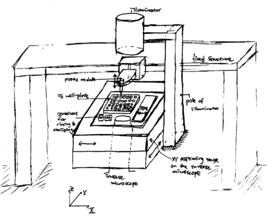
A number of design options are considered to meet the design concepts and require-ments of the robotic single-cell manipulator. The first design option, among many, considered for the system is illustrated in Figure 3-1. In this design, the inverse nii-croscope and the structure carrying the Z-axis mechanism are fixed in position, and
all containers (PDMS microwells, 96 well-plates, and small containers for rinsing and sterilizing) are located in an XY positioning stage. After the microscope stage moves to locate a target microwell or 96 well-plate, the pipette module comes down and picks/places the target cell. While this design has the advantage of no movement overlaps along any axes, it also has a critical downside that the positioning stage has to become bigger and bigger for more PDMS stamps or 96 well-plates.
Figure 3-1: One design option considered for the robotic single-cell manipulator.
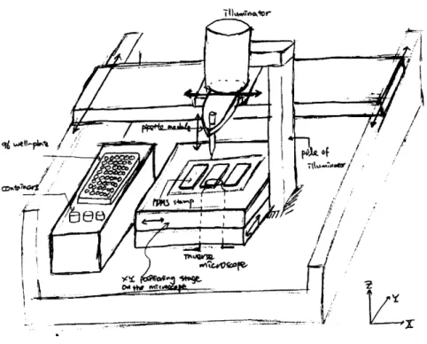
In order to overcome this drawback, we need to place 96 well-plates and small containers in another location, and this requires our system to have additional motion degree of freedom (DOF) since any retrieved cells from PDMS microwells have to be deposited in one of the 96 well-plates. This leads us to consider a gantry system as the next possible design, whose hand-sketch design is illustrated in Figure 3-2.
~I1&~o~r
Figure 3-2: Design of gantry configuration for the robotic single-cell manipulator.
This design allows the pipette module to have all 3 DOF along X, Y, Z axes, and so there are movement overlaps between the gantry and the positioning stage along the X and Y axis. This downside is, however, inevitable when we have PDMS stamps and 96 well-plates located in different places. Advantages of this design lie in the fact that gantry systems are commercially available and can easily have the submicron resolution which is more than enough for our application. However, it is notable that the upper stage of the gantry system can have a physical collision with the illuminator. When the pipette module needs to move along the Y-axis, the whole upper stage has to slide and the range of this motion is greatly limited by the illuminator's structural support pole shown in Figure 3-2.
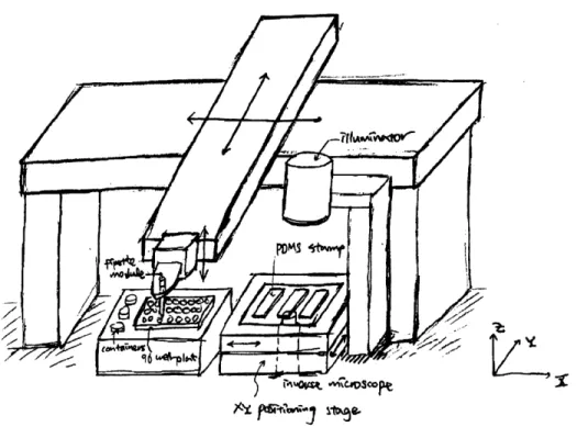
Another design of a T-drive system, illustrated in Figure 3-3, can remove this collision issue and provide freer movement along the Y-axis. This T-drive system is basically a combination of two linear stages with the upper one inverted so as
to reach into the inverse microscope and the 96 well-plates. This design can be a good choice for our system because many commercial linear stages are available at reasonable prices and the configuration is easy to build. Also, we can make a compact and accurate system out of this design with the right choice on linear stages, which is discussed in the following section.
Figure 3-3: Design of T-drive system for the robotic single-cell manipulator.
Among many options, we here choose the T-drive mechanism for our system design and we show the CAD model for this design in the next section with explanation on selected components.
3.1.2
Conceptual Configurations
Among several options for the proposed system, robotic single-cell manipulator, the T-drive mechanism is selected because it is easy to build with commercially available
linear stages and also can be integrated within a compact footprint. It also gives opening in the front area for users to work freely on the 96 well-plates and the PDMS microwells. The conceptual CAD design is shown in Figure 3-4 below. The footprint of this system is 670 mm x 800 mm.
I XY Positioner F
S -axis Actuator
l lu inator
& Pipette Module
96-well Plates PDMSmicrowells
S& Positioning stage
Microscope
Figure 3-4: Conceptual configurations for the robotic single-cell manipulator.
In this concept, which has not been constructed, the XY positioner of Figure 3-4 is composed of two linear stages from Aerotech: PRO 165-400 for X-axis motion and
PRO 115-200 for Y-axis motion. The Y-axis stage has a foldback which uses a timing belt to connect the parallel shafts of the ballscrew and motor so that we can save unnecessary space in the back. However, if the compactness is not a critical factor in design, it is more suggested not to use the foldback since it causes additional flexibility in the drivetrain which can degrade performance. Another noticeable design point is that a bigger stage, PRO 165-400, is selected for the X-axis motion. This is partially
because we need longer travel length along the X-axis line, but more importantly, this bigger stage augments the roll stiffness which is significantly necessary in this configuration. As explained earlier, the resolution of the XY positioner does not have
to be tight for the cell-retrieval process; however, for future purposes such as the deterministic cell-depositing task, it is preferable to have submicron resolution. This is why the PRO series from Aerotech are selected for the system. Both PRO series have the resolution and accuracy of 0.5 pm and +8 pm respectively and the maximum speed of 300 mm/s. Detailed specifications for these stages are provided in Appendix B.
The pipette module and the Z-axis mechanism are simplified in the figure and this part is detailed in the following section and Chapter 4. The inverse microscope in the figure is also a simplified version of an Olympus CKX 41 which has a positioning stage on it. The XY microscope positioning stage in this concept is a SCAN IM from a German company Marzhauser which has the resolution and acceleration of 50 nm
and 1m/s 2, respectively. The information on detailed specifications of both products
is provided in Appendix B. Instead of using this commercial inverse microscope, however, we plan to design and construct our own microscope, for the prototype, with a camera, a zoom imaging lens, and a microscope stage. We discuss this self-designed microscope in detail in the following section and Chapter 4.
3.2
Z-axis Mechanism Selection
We use a syringe system for the pick-and-place tasks and the end-effector which is the tip of a glass micropipette should be able to approach a microwell of interest to pick a target cell. It therefore requires Z-axis motion as well as XY plane motion. Many design options are considered for the Z-axis mechanism to provide the tip accurate access to the Z-axis motion. In this section, we discuss these options and how we select one among them.
3.2.1
Mechanism Options
There are a number of mechanisms that can be used for the Z-axis motion. With-out pondering too much on advantages and disadvantages, any possible approaches are first considered from a regular direct current (DC) motor to a linear pneumatic
actuator. These options are then categorized to two groups. Figure 3-5 shows the linear mechanism category for the Z-axis movement. The figures show the end of the Y-axis stage with a linear voice coil mechanism, lead-screw system, and a pneumatic actuator implemented respectively.
(a) Linear voice coil motor
(b) Lead screw mechanism
(c) Pneumatic actuator
Figure 3-5: Linear mechanism options considered for the Z-axis motion.
These options are very practical in that they directly provide vertical motion and have inherently perpendicular instantaneous velocity of the tip when touching the surface of PDMS stamps. The other category is for the rotational mechanisms,
shown in Figure 3-6, containing a regular DC motor system, a DC motor with a four-bar linkage, and a voice coil actuator mechanism.
(a) Regular DC motor
(b) Four-bar linkage
(c) Voice coil motor
Figure 3-6: Rotational mechanism options considered for the Z-axis motion.
These rotational mechanisms, except for some four-bar linkage systems, cannot provide linear motion; however, given that we only need a travel length of 10 to 20 mm, which is much smaller than the arm length (150 to 200 mm), the motion can be
close to straight line.
V4I
pow~
(a) Hoekens linkage
9u11o .
PPM1
(b) Peaucellier-Lipkin linkage
(c) Sarrus linkage or double SCARA
Figure 3-7: More options for the Z-axis motion with four-bar linkage structure.
In the brainstorming process, we also considered four-bar linkage systems giving
linkage and Peaucellier-Lipkin linkage create linear motion while the Hoekens linkage provides nearly straight line motion. However, for such a short range of 10 to 20 mm, using and implementing a four-bar linkage structure on the end of the Y-axis stage seem too complicated and not practical. Also, the linear guide will be hard to build with sufficient accuracy.
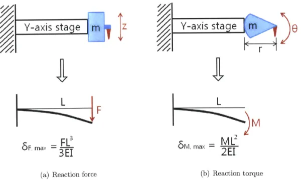
Before comparing pros and cons of each one of the options, we need to decide which group, either linear mechanism or rotational mechanism, can be a better choice in terms of reaction to the system and concern of error. For this purpose, let us consider the Y-axis stage on which the Z-axis mechanism is mounted as a cantilever beam with one end fixed. This cantilever beam would experience vertical reaction force when a linear mechanism actuates the end-effector up and down while it would be exposed to reaction torque or moment when a rotational mechanism actuates the tip. These are illustrated in Figure 3-8 along with the maximum amount of deflection in each case.
Y-axis stage
m
z
Y-axis stage
m
L
FL
H~4F
M
3m2
5F max ~
3
FL
5M, maxML
3E
2EI
(a) Reaction force (b) Reaction torque
Figure 3-8: Cantilever beams under the vertical reaction force and the reaction torque.
and area moment of inertia I. The additional structures for the linear or rotational motion are assumed to have the same mass m, and the reaction force and moment are assumed to be exerted on the end of the cantilever, which models the Y-axis stage. In the figures, the maximum deflections under the reactions are expressed in terms of the parameters [8]. In order to compare the deflection level, we need to find a link to connect the force, F to the moment, M. This link can be found by considering the fundamental condition for the Z-axis movement. The basic requirement for the end-effector is to move a certain distance within a certain amount of time. That is, if we want to locate the tip at the distance of d in the required time of t under the assumptions of initial rest and the constant acceleration of a, the distance and the acceleration are expressed as
1 4d
d = -at2 A a = t2. (3.1)
The force required is therefore
4d
F = ma = n d. (3.2)
As for the reaction torque, the angular acceleration, a is, in the same manner, expressed as
4d
a =(3.3)r~t2
where r is the rotation system tip to center distance.
With the worst case scenario for the rotational mechanism, the total mass of the extra structure rn is considered to be concentrated at the end as a point mass. Thus
the mass moment of inertia, J is equal to mr2. The torque needed to move the tip to
the distance d is therefore
M = Ja = mr2 = r 4d (3.4)
Accordingly, the relation between the force and torque is simply
M = rF. (3.5)
With this relation, we can decide which case has the larger deflection by looking
at the difference between 6Fmax and AI,max. If this difference is positive, the linear
mechanism causes worse reaction to the system with larger deflection, thereby making the rotational mechanism a better choice. Otherwise, the opposite conclusion can be made. The difference is
FL
3 ML2F,ma -- M,max = 3E - 2E (36)
After substituting M with Equation 3.5, canceling out terms and reorganizing, the difference becomes
2L
- r > 0. (3.7)
3
Since the arm (length of r) of the rotational mechanism is much shorter than the length (L) of the Y-axis stage, it can be said that the inequality of Equation 3.7, in general, is true and the rotational mechanism exposes less reaction and less deflection to the system. This is especially true when we can always reduce the length r by implementing a counter-balance mass because the value r is just the distance between the rotation axis to the center of mass. As a result, we can now choose the rotational mechanism group over the linear one.
Now, we need to choose one mechanism within the group shown in Figure 3-6. First, even though the four-bar linkage structure can provide relatively more straight motion to the tip, it is not very efficient to build this complicated structure for such a short travel length of 10 to 20 mm. As for the general DC motor case, it does have the advantage of easy installation; however, it is not a direct drive and so can have a backlash problem which can cause large enough error to the end-effector's motion. With other options ruled out, the voice coil actuator with the advantages
of both straightforward installation and direct derive is then selected as our Z-axis mechanism to give the accurate tip movement.
3.2.2
Actuator and Sensor
Now that we chose the Z-axis mechanism, we need to either build a voice coil actuator or find a commercially available one. Luckily we found an old hard disk drive manu-factured by IBM, shown in Figure 3-9, which has a well-constructed electromagnetic motor with a well-built-in bearing.
I
I
I
I
I
I
I
(a) with disks (b) disks disassembled
Figure 3-9: Built-in voice coil actuator in a hard disk drive.
The built-in voice coil actuator that we plan to use is indicated inside of the red box in Figure 3-9(b). It is notable that this device has the mechanical stop system indicated inside of the blue box. This stop system is there to prevent the coils from coming out of the magnet part. We do not mind to have this extra structure since we need only 10 to 20 mm travel length along the Z-axis line which corresponds to less than 20' given our designed arm length. In fact, we later use this hard stop as a
reference point of the Z-axis motion and this is detailed in Chapter 4.
While a current hard disk drive generally has the same kind of actuator with the arm of about 35 mm, this old hard disk drive has fairly big one with the 85mm-long arm and it actually makes this old device a better choice for our Z-axis actuator because it can be directly used with simple arm extensions. Figure 3-10 shows the CAD model of the actuator and several components for the extension we designed for this mechanism.
Inside
Block
Bracket
Counter-balance
weight
Figure 3-10: Arm extension design for the voice coil actuator.
The arm extension is designed to have several separate components rather than a single body for manufacturing purposes. By separating parts, it becomes easier to manufacture; the extension base can be first cut with a water-jet and then milled to have different height and necessary holes in required positions. The inside and outside blocks can be also manufactured in the same way. As for the bracket, a thin aluminum plate is first milled and then bent to have 90' angles. Every parts except for the counter-balance block are designed to be manufactured with aluminum alloy 6061 for its light-weight (density of 0.0027 g/mm3) and good machinability. On the
other hand, the counter-balance block is designed to be manufactured with brass
alloy 360 for its higher density (density of 0.0085 g/mm3) and good machinability.
possible directions and the counter-balance block is there to simply balance the arm. The importance of counter-balance is detailed in Chapter 4.
The assembled CAD model for the arm is shown in Figure 3-11 below. This figure also shows the pipette module mounted on the extension. The pipette module and its sealing components are discussed in Chapter 4 in detail. The total arm length from the shaft to the tip is 140 mm. We show the manufactured and assembled physical system in Chapter 4.
(a) Top view
(b) Isometric view
Figure 3-11: Assembled CAD model for the Z-axis actuator with arm extension.
3.3
Microscope and Microscope Stage
As explained before, we decide to design and construct our own microscope for the prototype instead of using a commercial one such as Olympus CKX 41 used in our
conceptual design in Figure 3-4. In this section, we discuss necessary components for an inverse microscope and their requirements. We also present the conceptual design in this section and the actual microscope system constructed is detailed in the following chapter.
3.3.1
Desired Specifications
The basic purpose of an inverse microscope is simply to provide users access to im-ages of specimens, which are, in our case, cells in PDMS microwells with the size on the order of 10 pm. Accordingly, in order to design our own microscope, the most fundamental components we need are a camera and a zoom imaging lens which have enough specifications to capture images of microscopic objects. The selected com-ponents including a camera, a lens, and other necessities are shown in Figure 3-12 below.
(a) CCD camera
(c) L-shape bracket
(b) Zoom lens
(d) Focus stage
Figure 3-12: Components for the self-designed inverse microscope.
The camera shown in Figure 3-12(a) is a charge-coupled device (CCD) monochrome
camera, Watec 902C. It has 768 x 494 pixels with the size of 8.4 x 9.8 ,m each. Ac-cordingly, only with this camera, it would be hard to capture clear images of 10 pm cells. This is why we need a zoom imaging lens, shown in Figure 3-12(b), which has a magnification level of 2.5x up to 10x. This lens is VZM 1000 model from Edmund Optics and the detailed specifications of the camera and lens are provided in Appendix B. Together with this lens, the camera can achieve a sensing area of 0.64 x 0.48 mm with the smallest pixel of 0.84 x 0.98 pm, which is enough to observe micrometer-sized objects. Since the zoom imaging lens has a specific working distance of 35 mm with the tolerance of ±1 mm, it would be of great help to have a command of adjusting this distance. The focus stage, shown in Figure 3-12(d), is used for this purpose. The L-shape bracket with opening in Figure 3-12(c) is the body of the self-designed microscope and provides a structural base for the microscope positioning stage, shown in Figure 3-12(e). This positioning XY stage has several piezoelectric motors in it and this is detailed in Chapter 4.
3.3.2
Inverse Microscope Design
We conceptually assemble those components explained in the previous section with a CAD tool and Figure 3-13 below illustrates the assembled model for our self-designed inverse microscope. M seicroscope XY Stage L-shape Bracket Lens Focus Stage Camralc
First, the L-shape bracket is mounted on the side of a granite table with the opening area facing upward. The focus stage with the camera and lens mounted is then assembled so that the lens is located in the middle of the bracket's opening. Lastly, the microscope positioning stage is mounted on the bracket. In the figure, a 96 well-plate, a PDMS stamp, and several small containers are located in the stage. We also plan to add an illuminator to this system. In Chapter 6, we discuss the illumination in more detail. The physical system for this inverse microscope has been built and we discuss it more in the following chapter.
Chapter 4
Mechanical Design and
Implementation
In this chapter, we discuss how the conceptual design of the proposed system and selected components detailed in the previous chapter are used to construct the pro-totype of the system. We then explain several important parts of the propro-totype in more detail and talk about how they are implemented. A critical issue of the exist-ing commercial system is also addressed in this chapter with suggested solutions and supporting experiments.
4.1
Prototype of the Single Cell Picker
Conceptual configurations for the proposed system, robotic single-cell manipulator, are designed and discussed in Chapter 3, and here we present the prototype for the system. This prototype has been constructed mainly to see the feasibility and performance of the proposed system and it focuses largely on the accuracy of the Z-axis movement. For the prototype, the XY positioner in Figure 3-4 from Chapter 3 is replaced with mechanical XY stages and the inverse microscope has been self-designed and constructed with a simple monochrome camera, a zoom lens, and a XY microscope stage. More importantly, the Z-axis mechanism part together with the pipette module has been built and mounted on the XY mechanical stages. This
part mainly consists of the voice coil actuator from an old hard disk drive selected in the previous chapter, an arm extension, and an optical encoder. We discuss each component and their implementations in detail in the following sections. Figure 4-1 below shows the prototype of the robotic single-cell manipulator.
Illuminator '
Z-axis Actuator &
Pipette Module
XY Positioer
-Microscope
& XY Stage
RT Monitor
Syringe Pump
NI PXI Chassis
(RT, FPGA, Vision)Figure 4-1: Physical configurations of the prototype.
Illuminator
Microscope
& XY Stage
Z-axis Actuator &
Pipette Module
._XY Positoe
Figure 4-2: Partial configurations of the microscope and z-axis mechanism.
The main controller for this prototype, shown in Figure 4-1, is a National Instru-ments (NI) PXI controller containing a real-time processer, a field-programmable gate
array (FPGA) card, and an analog vision card. Labview is used as a programming tool for this controller and we discuss how the entire prototype is integrated with this PXI controller in the following chapter. A syringe pump is used with polyether ether ketone (PEEK) tubing in order to be able to aspirate and dispense individual cells or microbeads from the PDMS microwells to the 96 well-plates. An illuminator is also included to provide better contrast for the microwells' images captured from the inverse microscope. Detailed information on these parts is provided in the following sections. Figure 4-2 shows the Z-axis mechanism and the pipette module part in more detail.
4.2
Picking Method
4.2.1
Syringe Pump
An original equipment manifacturing (OEM) syringe pump with 60 mm stroke is used in the prototype for the process of cell-retrievals. This syringe pump, Cavro XLP 6000, driven by a stepper motor with a Teflon coated leadscrew controls the volume of growth medium aspirated with a cell and the flow rate as well. Together with a 50 pL syringe, this device has the approximate resolution of 1 nL and the average speed range of 5.2 nL/sec to 42 pL in the 48000 microstepping mode. All these settings can be controlled with a simple serial communication using RS-232 at a baud rate of 96000. Figure 4-3 below shows a picture of the syringe pump. As shown in the figure, this device includes a multi-channel valve system so that the growth medium can be automatically refilled; one valve is connected to a medium reservoir and another to the pipette module through PEEK tubing. As explained, all the commands can be sent to the syringe pump through a RS-232 serial communication and we built an user interface (UI), shown in Figure 4-4, with Labview to command this device. The detailed Labview coding is provided in Appendix A.
To pipette
module
To medium
reservoir
Figulre 4-3: OEM syringe puimp for the process of cell-retrievals.
4.2.2
Issues with Leakage
In using a syringe pump and running a liquid to pick and place a cell or microbead, it is important to make sure that all components are appropriately connected and sealed. This is especially true when the device runs under high pressure conditions. Since micropipettes used for cell-retrieval pi-ocess have a very small tip opening of 30 pm or 50 pm, the pipette module is inevitably exposed to relatively high pressure during the process of cell-retrieving and disposing. Any failure on sealing, therefore, can cause serious leakage problem, thereby bringing about poor cell-retrieval performance. Figure 4-5 shows a picture of the commercial system with the types of the fittings used in it.
Luer-lok Fitting
- Teflon Tubing
Plug with Ferrule Adapte
ipette
Figure 4-5: Cellcelector with its sealing components.
As indicated in the figure, in the CellCelector, a glass syringe is mounted on a syringe pump and connected to a micropipette through several fittings. Teflon tubing with a Luer-lok fitting connects the glass syringe to an adapter. The Luer-lok is a standard fitting which provides the connection between the syringe and the tubing, and the other end of the tubing is connected to the adapter with a plug and an inside ferrule. A micropipette is also attached to the other end of the adapter with a plug and a ferrule to make sure that the liquid from the glass syringe only runs to the tip of the pipette. However, leakage has been detected in the existing system while running from the point where the Teflon tubing is connected to the adapter. This leak point
is illustrated in more detail in Figure 4-6. This leakage issue has been observed with both 30 pm and 50 pm-OD micropipettes, but more seriously with the 30 pm one.
TelnTubing
<-
Ferrule
-A da pte r
8 M opipette
(a) Unassembled (b) Assembled
Figure 4-6: Schematic of how fittings work to seal the pipette module.
Figure 6(a) shows the positions of the fittings just before assembly and Figure 4-6(b) indicates the cross-section of the assembled pipette module. As shown in the figure, the inside ferrule is the main component for sealing between the tubing and the adapter. When the plug is fastened, it presses the ferrule so that the ferrule can seal the tubing by squeezing it. This squeezing effect is indicated as horizontal pressures with red arrows in Figure 4-6(b). Even though the pipette is connected to the adapter in the same way the tubing is, the leakage mostly occurs at the point where the tubing meets the adapter. This makes the material of tubing, which is Teflon, a likely cause of failure. Teflon is actually the brand name of the DuPont Company, for polytetrafluoroethylene (PTFE), and this material is commonly used in chemistry and biology due to its good chemical resistance. However, when it comes to mechanical properties, Teflon has a relatively small yield strength compared to other polymers such as PEEK. The compressive yield strength of Teflon is 10