HAL Id: tel-01540873
https://tel.archives-ouvertes.fr/tel-01540873
Submitted on 16 Jun 2017HAL is a multi-disciplinary open access archive for the deposit and dissemination of sci-entific research documents, whether they are pub-lished or not. The documents may come from teaching and research institutions in France or abroad, or from public or private research centers.
L’archive ouverte pluridisciplinaire HAL, est destinée au dépôt et à la diffusion de documents scientifiques de niveau recherche, publiés ou non, émanant des établissements d’enseignement et de recherche français ou étrangers, des laboratoires publics ou privés.
Composites with bundle mesostructure : elastic
properties and damage
Hana Zrida-Ammar
To cite this version:
Hana Zrida-Ammar. Composites with bundle mesostructure : elastic properties and damage. Mechan-ics of materials [physMechan-ics.class-ph]. Université de Lorraine, 2016. English. �NNT : 2016LORR0280�. �tel-01540873�
AVERTISSEMENT
Ce document est le fruit d'un long travail approuvé par le jury de
soutenance et mis à disposition de l'ensemble de la
communauté universitaire élargie.
Il est soumis à la propriété intellectuelle de l'auteur. Ceci
implique une obligation de citation et de référencement lors de
l’utilisation de ce document.
D'autre part, toute contrefaçon, plagiat, reproduction illicite
encourt une poursuite pénale.
Contact : ddoc-theses-contact@univ-lorraine.fr
LIENS
Code de la Propriété Intellectuelle. articles L 122. 4
Code de la Propriété Intellectuelle. articles L 335.2- L 335.10
http://www.cfcopies.com/V2/leg/leg_droi.php
Ecole doctorale EMMA
Institut Jean Lamour –UMR 7198- Département SI2M – Equipe 305 Parc de Saurupt - CS 50840- 54011 NANCY Cedex
Université de Lorraine – Pôle M4 : matière, matériaux, métallurgie, mécanique
THÈSE
Pour l’obtention du titre de:
Docteur De L’université De Lorraine En Mécaniques et Ènergétique.
Présentée par :
HANA ZRIDA AMMAR
Thèse soutenue publiquement le 30 mai 2016 à Luleå (Suède) devant le jury suivant :
Prof. Steve Ogin Department of Mechanical Engineering Sciences, University of
Surrey, United Kingdom Rapporteur
Prof. Yves Berthaud Université Pierre et Marie Curie, Laboratoire de Mécanique et
Technologie, Cachan, France Rapporteur
Prof. Povl Bronsted DTU WIND ENERGY, Department of Wind Energy, Technical
University of Denmark Examinateur
Prof. Stepan Lomov Composite Materials Group, University of Leuven, Belgium Examinateur
Prof. Ali Kallel Laboratoire des Matériaux Composites, Céramiques et
Polymères, Université de Sfax, Tunisie Examinateur
Prof. Zoubir Ayadi Département Science et Ingénierie des Matériaux et
Métallurgie-IJL, Université de Lorraine, Nancy, France Directeur de thèse
Chaired Prof. Janis Varna
Department of engineering sciences and mathematics, division of material science, polymeric composite materials, Luleå university of technology, Sweden
Directeur de thèse
Les composites avec mesostructure en faisceaux :
Propriétés élastiques et endommagement
“The important thing is to not stop questioning. Curiosity has its own reason for existence. One cannot help but be in awe when he contemplates the mysteries of eternity, of life, of the marvelous structure of reality. It is enough if one tries merely to comprehend a little of this mystery each day”
“Student: Aren't these the same questions as last year's physics final exam? Dr. Einstein: Yes; But this year the answers are different.”
ii
Preface
The work presented in this thesis has been carried out within the Division of Materials Science in Luleå University of Technology in Sweden and in the Division of Mechanics of Materials (SI2M) in Jean Lamour Institute in University of Lorraine France during the period from October 2011 to December 2015.
This thesis could not have seen the light of day without the precious support of many persons.
There is no way I can ever thank my both supervisors Professor Janis Varna and Professor Zoubir Ayadi for their unconditional and unswerving help, for their precious time, for their valuable advices, for their patience and for their willingness to listen and their whole-hearted readiness to help when I most need it. Words just fail me whenever I try to express my gratitude for them, thank you for making my research experience ever so unique.
I gratefully acknowledge my co-author Dr. Erik Marklund for his assistance in my research and for shearing his knowledge and for his contributions.
I would like to express also my sincerest gratitude to my co-author Docent Patrik Fernberg for his support and guidance and for his fruitful suggestions and remarks. It is a pleasure to thank the Joint European Doctoral Program in Material Science and Engineering (DocMase) for financing part of this project. My acknowledgments go also to the local government Norbotten in Sweden for financing part of this research work and also Swerea SICOMP for their support.
I would like to offer my special thanks to Professor Zouhir Fakhfakh from my home country (Tunisia) for his encouragement and his personal support. Special thanks go
iii
also to Professor Roberts Joffe and Professor Lennart Wallström for their kind help. Many thanks go to my colleagues and my friends who were important to the successful realization of my thesis.
Finally, I owe my deepest gratitude to my relatives, my parents, my brother and my husband for their love, prayer, support, care and encouraging words that light my way and kindle my enthusiasm to bring out the best in me in all my academic endeavors. Luleå, May 2016
iv
Abstract
Many types of composite materials are today used in various types of load carrying structures, due to their excellent strength and stiffness to weight ratio. Simplicity, reliability and low cost of the material processing are important factors affecting the final selection.
With the textile reinforced composites, the cost-efficiency is reached by using dry preforms which are impregnated by resin infusion, resin transfer molding etc.; this have made a break-through and have been widely used.
Textile composites with bundle meso-structure have been studied in this thesis for elastic properties and damage investigations.
In chapter I a state of the art was conducted the different methods for elastic properties determination in composites with bundle mesostructure and mesostructure heterogeneity. The different damage features occurring in such composite materials are also investigated.
Chapter II of this thesis deals with elastic properties modeling for Non-crimp fabric (NCF) based composites for investigating the effect of meso-structure defects on mechanical properties degradation. The objective of the work is to formulate a model for the NCF composite mesostructure in an attempt to investigate the effect of the waviness on stiffness reduction. Moreover, the stiffness calculation methods for the complex geometry are explained and justified and finally, the different geometrical parameters changes are taken into consideration and included in the calculation. The damage initiation and development is presented in chapter III, where woven fabric composites designated for high temperature application were investigated under severe thermal conditions to study their thermal stability and their resistance to thermal damage. The mechanical performance of the same composites was studied. The effect of aging was also investigated. 3D models were realized with Finite elements in order to explain the edge effect on the evolution of the cracks observed during the tensile tests. In addition, the differences and similarities in cracking in
v
different layers were analysed using probabilistic approaches (a simple one as well as Mo te Ca lo si ulatio s ith Hashi ’s a d also shea lag odel a d f a tu e mechanics arguments.
vi
List of relevant publications and presentations
Journal papers
[1] H.Zrida., E. Ma klu d., J.Va a a d ).A adi., Effe ti e stiff ess app oa h fo stiff ess of ia ial o posites ith a i g lo al u dle a i ess , International journal of solids and structures, 2016 (submitted)
[2] H.Zrida., P.Fe e g., J.Va a a d ).A adi., Mi o a ki g i the all aged Ca o fi e/pol i ide la i ates su je ted to te sio , Composites Part B: Engineering, 2016 (submitted)
[3] H.Zrida., P.Fe e g., J.Va a a d ).A adi., Mi o a ki g i the all led a d aged Ca o fi e/pol i ide la i ates , Composites Part A: Applied science and manufacturing, 2016 (submitted)
[4] H.Zrida., E. Ma klu d., J.Va a a d ).A adi., Maste curve approach to axial stiffness calculation of biaxial composites with bundle waviness , Composites Part B: Engineering, 2014 (64), 214-221.
[5] H.Zrida., E. Marklund., J.Varna and Z.Ayadi., Effe ti e stiff ess of °-layer for stiffness determination of cross-ply non-crimp-fabric co posites , Journal of reinforced plastics and composites, 2014 (33), 1339-1352.
vii
Conference papers
[6] H.Zrida., P.Fernberg., J.Varna and Z.Ayadi., Effe t of e t e e te pe atu es o micro-da age de elop e t i CF/pol i ide la i ates , Conference paper: 20th
international conference on composite materials ICCM 2015, Copenhagen, Denmark.
[7] H.Zrida., M“.Loukil., J.Va a a d ).A adi., C a k ope i g displacement determination in damaged cross-ply laminate using electronic speckle pattern i te fe o et E“PI , Conference paper: IOP Conference series: Materials Science and Engineering, 2012
[8] H.Zrida., K.Gia adakis., J.Va a a d ).A adi., The effect of meso-strucure heterogeneity on the cracks initiation and the displacement distribution in NCF o posites , Conference paper: IOP Conference series: Materials Science and Engineering, 2012
viii
List of Conference Presentations
20th International conference on composite materials (ICCM) July 2015,
Copenhagen, Denmark (Oral presentation)
18th International conference on mechanics of composite materials (MCM),
June 2014, Riga, Latvia (Oral presentation).
International conference on composite materials and renewable energy applications (ICCMREA), January 2014, Sousse, Tunisia (Oral presentation).
International conference DFC12/S16: 12th Deformation and fracture of
composites and 6th Structural Integrity, April 2013, Queen's College Cambridge,
United Kingdom (Oral presentation).
6th EEIGM International conference in Advanced Materials Research,
x
Contents
Dedication ... i
Preface ... ii
Abstract ... iv
List of relevant publications and presentations ... vi
Chapter I. State of the art ... 2
1. Inroduction: Fibre reinforced composites ... 2
2. Mechanical properties in composites with bundle meso-structure ... 6
3. The damage features in textile composites ... 9
3.1. Matrix crack (intralaminar cracking) ... 10
3.2. Delamination (Interlaminar cracking) ... 11
3.3. Fibres break ... 11
3.4. Matrix cracks in bundles structures composites ... 12
3.4.1. Longitudinal cracks ... 13
3.4.2. Whole cracks (Transverse cracks) ... 13
3.4.3. Half cracks (Transverse cracks) ... 14
3.4.4. Double cracks (Transverse cracks) ... 14
3.5. More studies on damage accumulation in textile composites ... 15
Chapter II. Effect of mesostructure defects on elastic properties of textile composites ... 19
xi
1. Introduction ... 19
2. FE modelling procedure (Material, geometry and assumptions) ... 23
3. Effective stiffness determination using isolated beam subjected to appropriate boundary conditions ... 26
3.1. Meso-scale homogenization ... 29
3.2. Effect of wavelength and amplitude on laminate stiffness ... 30
3.3.Predictions based on isolated curved layers with boundary conditions used in previous studies ... 31
3.4. The layers effective stiffness dependence on A/t0 and L/t0 ... 32
3.5. Approximation of tractions at the 0/90 layer interface ... 36
3.6.Composite stiffness based on effective stiffness of an isolated 0-layer with surface loads ... 39
4. Effective stiffness determination using master curve approach ... 43
4.1. NCF stiffness knock down factor ... 47
4.2. Master curve approach... 48
4.2.1. Knock down factor curve and fitting function... 48
4.2.2. Validation and application of the master curve approach ... 50
5. Master curve approach for effective stiffness of composite with more complex geometries ... 56
5.1. Geometries ... 56
5.2. Development of the master curve approach ... 58
5.3. Engineering approach for the amplitude and wavelength's of an equivalent cell 60 5.4. Stiffness of chain of cells... 63
xii
5.5. Interaction effects of curved bundles in cells connected in parallel ... 65
6. Conclusions ... 73
Chapter III. Damage in carcon fibre/polyimide laminate ... 79
1. Introduction ... 79
2. Objectives ... 81
3. Experiments ... 81
3.1. Materials description ... 81
3.2. Experimental procedure ... 83
4. Results and discussions ... 85
4.1. Void content and initial damage state... 85
4.2. Damage state at RT in thermally cycled composites ... 92
4.3. Damage state at RT in aged composites ... 97
4.4. Damage state in mechanically loaded composites ... 102
4.5. Damage accumulation analysis ... 107
4.5.1. Theoretical background ... 107
4.5.2. Multiple cracking in 90-+45 layers of not aged (NA) composites ... 112
4.5.3. Multiple cracking in 90-+45 layers of (A) composites ... 118
4.5.4. Extraordinary cracking pattern in -45layers ... 120
xiii
Chapter IV. Summary, conclusions and perspectives ... 125
Acknowledgments ... 129
Appendix A ... 130
2
Chapter I
State of the art
1.
Introduction: Fibre reinforced composites
The quest of weight gain using materials with superior specific properties, engages the interest of many researches to explore composite materials. Each year, composites find their way into hundreds of new applications from golf clubs and tennis rackets to jet skis, aircraft, missiles and spacecraft.
Composite materials are widely used in different areas such as aeronautics (helicopter blades, pressure bulkhead, cargo door, etc), maritime transport (boats, etc), automotive industry (car roof, car carline, etc), electronic (insulation, mounting printed circuit, boards, etc), buildings (furniture, roofing, etc), industry (tanks, pipes, wind turbine blades, etc) and even in sports and entertainment (skis, fishing rods, helmets, et …
A composite material consists of an assembly of different immiscible materials which complement each other and bring about a material whose physical properties are better than those of the individual constituents working separately.
Polymer composites are formed with reinforcement in the form of particles or fibres embedded in a matrix. The matrix is often a thermoplastic or a thermoset polymer. The matrix preserves the geometric arrangement of fibres, protects them from the environmental attack and damage, to which the sample can be exposed. The fibres can have inorganic or organic nature such as carbon fibres, glass fibres, oxide fibres, silicon
3
carbide fibres, etc. They can be continuous or discontinuous filaments. The high stiffness and strength of polymer composite materials stems from the high stiffness and strength of fibres. Their geometry allows them to have minimal defects and their composition gives them a high strength. The fibres work as reinforcements since the load is transferred to them from the matrix. The volume fraction of fibres for a structural composite is typically 45%-65%. The maximum theoretical value is 79% for square array and 91% for a hexagonal array [1].
The fibres can be arranged in different ways: homogenously or uniformly dispersed like in pre-impregnated tape laminates or in form of bundles like in the woven reinforced composites or the non-crimp fabric composites.
The pre-impregnated tape laminate, shown in Figure I-1 [2], is a stack of unidirectional plies in which the layers are perfectly bonded to each other and the mechanical properties depend on their orientations.
Figure I-1. Internal structure of pre impregnated tape based
cross ply laminate [2]
The main advantage of this material is the high fibre volume fraction that can be obtained with well aligned fibres, showing an excellent in-plane stiffness and strength. The problem with this material is that it is expensive. The high costs combine the high
4
labour costs and the high storing costs (pre-impregnated tapes require low temperature to prevent curing). Another drawback is the sensitivity to inter-layer delamination cracking under impact loading due to their poor interlaminar fracture toughness [3].
This problem is solved with woven composites shown in Figure I-2 [4], the reinforcing fibres are assembled in bundles in different directions and form a fabric.
Figure I-2. Images of E-glass (left) and basalt (right) woven fabrics [4]
This composite has two-directional reinforcement and its manufacturing cost is lower than that of the pre-impregnated tape based composite. The woven structure shows high waviness in the out-of-plane direction. This waviness brings advantages to the material by improving its fracture toughness and its mechanical properties in the out-of-plane direction. But, it brings also significant drawbacks to woven composite by reducing the in-plane properties.
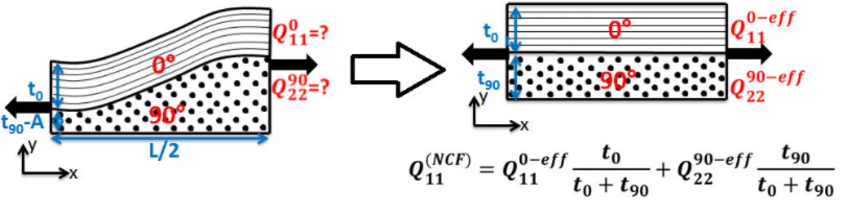
Some drawbacks of the pre-impregnated tape based composites and of the woven composites are overcome with new type of textile composite called non-crimp-fabric composites (NCF) presented in Figure I-3 [5].
5
Figure I-3. Schematic diagram showing a multi-axial non-crimp fabric [5]
NCFs are relatively new class of textiles in which a fabric is constructed of layers of fibre bundles aligned in specific directions [6]. The layers of fibres are produced by laying tows next to each other in a specified direction and subsequently employing a secondary fine yarn knitted around the tows to hold the fabric in place. The use of through-thickness stitching allows for improvement in damage tolerance and in the interlaminar fracture toughness. For textile composites (woven and NCF), the manufacturing technique provides a dry preform (fabric) which can be used in complicated shapes before it is consolidated into the final composite by resin transfer moulding with low manufacturing costs comparing to the pre-impregnated tape based composite. NCF composites, ideally, would combine a good in-plane response, like pre-impregnated tape based composites and the good through-thickness stiffness and strength due to the stitching in the thickness direction [7].
With bundle mesostructure, the woven and NCF composites show heterogeneities in the micro- and the meso –scale as shown in Figure I-4 [8]. The micro-scale heterogeneity can be seen from the microstructure of the fibre-matrix inside the bundles, the meso-scale heterogeneity is due to the structure of layers where the fibre bundles are separated by the matrix.
6
Figure I-4. Hierarchical structure of the NCF composites [8]
As it is shown in Figure I-4, the 0°-tows are far from being ideally oriented and present waviness in the out-of-plane direction. The stitching yarn induces waviness which leads to the in-plane stiffness reduction. The waviness occurring in NCF composites are similar to that can be seen in woven reinforced composites with lower amplitudes.
2.
Mechanical properties in composites with bundle
mesostructure
In order to study the mechanical properties dependence on the architecture parameters, finite element analysis and theoretical analysis methods are more convenient than the experimental techniques because of the complex geometry and the numerous parameter controlling the mechanical behaviour of the textile composites [9-10].
Finite element method (FE) started with Ritz who developed an effective method for an approximate solution of problems in the mechanics of deformable solids [11-12]. FE
7
is a numerical method for finding approximate solutions to boundary value problems for differential equations. It uses variational methods to minimize an error function and produces a stable solution. The problem is transformed to an equivalent one in terms of properties and geometry and the method is based on the discretization principle which is translated by the choice of a mesh that occurs by dividing the studied area into sub-domains with simple geometry (triangle, quadrilateral, etc) and with finite dimensions, hence the fi ite ele e t ethod’s a e. Results a e determined for each element. The accuracy of the results is directly related to the mesh quality realized (number of element, their distribution in the structure, form of element, etc). In FE analysis many errors can be produced, such as wrong interpretations of the physical model, mechanical modelling errors due to many assumptions like geometric simplifications and resolution errors which are due to problems of numerical accuracy. The engineer must be aware of the existence of these errors and must be able to estimate a level of confidence in the results.
Many researches have been conducted for predicting the mechanical properties of textile composites. The basic principle to determine the elastic properties of a textile composite using FE is to divide the structure into unit cells and then mechanical properties are calculated for the unit cell.
Since the textile composites have a complex architecture it is not easy to incorporate all geometrical parameters and simplifications are needed in the FE modelling [13].
Naik et al. [14-16] proposed a 2D crimp model for the elastic analysis of a 2D plain weave. The unit cell in this model was divided into sections and then the series-parallel
8
models were used to estimate the lower and the upper bounds of the elastic constants.
Ishika a a d Chou de eloped the osai odel [17], the fibre u dulatio odel
[18] a d fu the the idgi g odel [19] for analysing the elastic behaviour of woven
hybrid composites. In these models a fabric composite was simply regarded as an assembly of blocks of cross-ply laminates neglecting the shear deformation in the thickness direction.
Byström at al. [20] developed a homogenization method for stiffness matrix computation of woven composites; the method was called reiterated homogenization. The authors studied the linear elastic problems with periodic microstructure, which justifies the use of representative volume element which is enough to represent the elastic properties of the whole material.
More recent study was performed by Riccio et al. [21] who developed a representative volume element (RVE) for NCF composites under tension loading taking into account the to ’s a i ess a d the stit hi g. The classical micromechanical theory was used together with the stiffness averaging method. It was demonstrated that the exclusion of the to ’s a i ess f o the odel leads to a ig e o of the stiff ess o pa i g to the experimental data. However, the lack of stitching in the model is less relevant leadi g to a s all e o that a e egle ted. The stiff ess depe de e o the to ’s waviness was investigated and it was shown that this stiffness strongly depends on the waviness.
A mesoscopic FE model of the NCF structure was realized by Drapier [22] in order to investigate the interlaminar shear behaviour of non-crimp fabric composites. The
9
geo et i al hete oge eit as take i to a ou t. The to ’s i p as o side ed large enough for the composite to be regarded between the pre-impregnated tapes and the woven structures. This waviness was assumed as sinusoidal shaped characterized by a wavelength and amplitude. The same assumption was used in [23] by Edgren et al. where the authors used Timoshenko beam theory in addition to FE to calculate the stiffness of a layer in the NCF composite considered like a single curved beam. In addition to this assumption, Mattsson et al. [24] demonstrated that the 90°-layer with bundle mesostructure can be replaced by homogenized 90°-90°-layer without losing accuracy in the NCF laminate stiffness investigation.
One more important geometric parameter that should be taken into consideration while modelling textile composites, is the inter-strand gap between the bundles, it has been demonstrated in [25] that a change in the inter-strand gap width leads to a significant modification of the elastic properties (elastic modulus, shear modulus and Poisso ’s ratios) because of the change of the fibres volume fraction and the matrix volume fraction inside the layers.
3.
The damage features in textile composites
In order to have confidence in the structural integrity of composite components, designers must have a good understanding of the effect of stress concentrations which lead to the damage. Studies of initiation of cracks, their growth characteristics and their effect on the laminate properties belong to an active field of study called damage mechanics, playing a central role in the assessment of durability and damage tolerance of composite structures.
10
Composite structures can undergo multiple micro-cracks before losing ability to carry the design loads. The damage mechanisms occurring in textile composites are basically the same as in pre-impregnated tape based composites. It mainly consists of matrix cracking, delamination and fibres fracture [26] presented in Figure I-5.
Figure I-5. Damage mechanisms in laminates [27]
3.1.
Matrix crack (Intralaminar cracking)
The stiffness and strength of fibre reinforced composites are higher in the longitudinal direction than in the transverse one. In addition, the stiffness of the reinforcing fibres is significantly higher than the matrix material. Thus, stress concentrations occur in the matrix when a ply is loaded in the transverse direction. The stresses at which the failure occurs in off-axis ply are lower than that of plies aligned in the loading direction. In the off-axis plies, the cracks develop and run parallel to the fibres direction. These cracks are usually the first mode of damage in fibre-reinforced composites. Such cracks are caused by tensile loading, fatigue loading, as well as by changes in temperature or by thermal cycling. Matrix cracks do not cause a total failure of the composite, but may
11
lead to significant degradation of the elastic properties and to appearance of other damage modes. An example of matrix crack is presented in Figure I-6.
Figure I-6. Matrix crack [28].
3.2.
Delamination (Interlaminar cracking)
The delamination is a longitudinal crack in the interface between two adjacent plies. Its propagation leads to the separation of the layers. This mode of damage causes the rapid deterioration of the mechanical properties and the total failure of the composite structure. An example of delamination is presented in Figure I-7 where it shows how it is starting from the matrix crack tip.
Figure I-7. Delamination starting from a matrix crack tip [28]
12
As its name says, it is the breaking of the fibres oriented parallel to the loading direction. In a unidirectional composite loaded in tension along the longitudinal direction, the fibres fail at their weak points and stress redistribution between fibres and matrix occurs, affecting other fibres and breaking more of them. An example of broken fibres is presented in Figure I-8.
Figure I-8. Broken fibres [28]
3.4.
Matrix cracks in bundle structured composites
Damages can occur in the textile composites in different length scale, either on the micro scale or on the meso scale. Figure I-9 represents the different types of cracks occurring within the fibre bundles introducing after a tensile test.
13
Figure I-9. Schematic showing the four crack types observed in NCF cross-ply
laminates � refers to crack densities of the different type of cracks [29].
The maximum cracks density is inversely proportional to the ply thickness [30].
3.4.1.
Longitudinal cracks
Longitudinal cracks are presented in Figure I-10. They can appear either within the bundle or at the bundle-matrix interface. They occur on the loading direction and they appear at high strains. This type of cracks never occurs in composites with uniform fibre distribution. They can appear due to fibres tow waviness at strains between 0.39% and 0.66 % [29-30].
Figure I-10. Micrograph of novel longitudinal cracks occurring in the 90°layer of the
NCF cross-ply laminate [29]
3.4.2.
Whole cracks (Transverse cracks)
Figure I-11 shows some whole cracks which extend from one 0°layer to another
14
Figure I-11. Examples of whole cracks running through two neighbouring
90°fibre bundles of the cross-ply NCF laminate [29]
3.4.3.
Half cracks (Transverse cracks)
Figure I-12 shows the half cracks which are contained in a single 90° fibre bundle
without connection with others existing in adjacent fibre bundles. This is the first type of cracks to occur in NCF composites [29].
Figure I-12. Examples of half cracks in 90°fibre bundles of the cross-ply NCF laminate [29]
3.4.4.
Double cracks
Figure I-13 shows double cracks which are a combination of half crack and longitudinal
15
Figure I-13. Examples of double cracks in single 90° fibre bundles of the cross-ply NCF
laminate [29].
The same type of cracks were also characterized and studied by John et al. [31] in 3D woven Fabric.
Edgren et al. demonstrated in [29] that the amount of whole cracks found in NCF o posites is s all a d does ’t e eed . /mm. The half cracks are more abundant than whole cracks and appear earlier. But their effect on stiffness degradation is moderated in NCFs comparing to the pre-impregnated tape based composites. It was proved that the ° la e ’s da age does ’t ha e a i po ta t effe t o the You g’s modulus which decreases slightly, since the laminate modulus is mainly controlled by the 0° non-damaged laminate. However, it has a strong effect on the degradation of the Poisso ’s atio e ause the t a s e se a ks i ease the strain in the load direction and reduce contraction in the transverse direction. The appearance of the new longitudinal cracks was explained by the stress concentration caused by the forced straightening of the 0° fibre bundles in tension.
3.5.
More studies on damage accumulation in textile
16
The complexity in geometry of the damage and its quantification has made the progress in studying the effect of the damage accumulation on the mechanical properties in textile composites slower than in composites with uniform fibres distribution.
Gao et al. [32] have studied the relationship between the mechanical properties and the damage accumulation in woven fabric laminate under quasi-static loading. The shear lag analysis, originally derived for the pre-impregnated tape based laminate, were employed idealized laminate replacing the woven one (Figure I-14), since in the studied eight-hardness satin fabric, the inter-crimp distance is quite large. It has been de o st ated that the You g’s odulus is affe ted little ith the a u ulatio of matrix cracks and crimp delaminations until the saturation of the crack density. The Poisso ’s atio as much more sensitive to the damage.
Figure I-14. Idealization of two layer woven fabric laminate [32]
Lomov et al. [33] presented an experimental methodology to study the initiation and development of damage in textile composites in tension test, which was applied to
17
different textiles: woven and NCFs. This methodology is based on full field strain measurement for studying the strain map, on a X-Ray inspection for studying the cracks placement, orientation and their length distribution, on a C-Scan for the damaged samples in order to study the damage extend and periodicity and finally on SEM for micro-characterization of damage.
The damage pattern in NCF composites was studied in [34], it was demonstrated that the cracking occurs periodically showing that there is a relation between the stitching and the damage pattern.
During the service life, the composite materials are not only exposed to mechanical loading but also to thermal loads. In [35], the effect of accelerated aging condition on woven fabric composite was analysed. A glass fibres eight-hardness satin weave with two different epoxy matrices (120°C and 180°C) was studied. When the fibres are protected with better matrix they are less sensitive to the thermal aging effect and they have better performance under mechanical loading.
19
Chapter II
Effect of meso-structure defects on elastic
properties of textile composites
1.
Introduction
Due to highmaterial costs and sensitivity to out-of-plane loads (e.g. impact damage) of pre-impregnated tape based composites, new manufacturing methods and material architectures based on dry preforms have been employed in the last decade producing civil aircraft primary structures. Non-crimp fabric (NCF) reinforced composites are particularly attractive due to their relatively high performance with less drop in the in-plane properties compared to traditional woven architectures, reasonable cost and ease of handling during manufacture. As a result there is a strong interest among aircraft manufacturers and within other sectors such as wind energy and automotive industry, to use NCF based composites in primary structures.
NCF composites are manufactured from layered textile preforms consisting of fibre bundles with a certain orientation assembled by warp-knitted threads [36]. This production technique allows for substantial reductions in production costs compared to pre-impregnated tape based materials. In addition improvements in damage tolerance as well as out-of-plane fracture toughness have been reported [37-39]. During composite manufacture, preforms are stacked in a mould and infiltrated by a thermoset resin to form the composite. Thus an NCF composite is created which is heterogeneous not only on microscale (fibres and resin) as for pre-impregnated based
20
composites, but also on mesoscale due to the appearance of distinct fibre bundles and resin pockets. Since the bundle scale is much larger than the fibre scale, homogenization over the fibre/matrix scale is possible representing the bundle as transversally isotropic material.
Ideally, NCF composites would consist of perfectly aligned fibre bundles where the size of each bundle is determined by the stitching procedure. However, due to the complex manufacturing technique, NCF composites have both in- and out-of-plane waviness of the bundles which reduces the in-plane stiffness. In [22,40] experimental data regarding the measured out-of-plane waviness are discussed, and the waviness in terms of sinusoidal shape was used in a 2D FE-model of a composite with periodic structure in the thickness direction and a biaxial NCF as a repeating unit cell (RUC) in order to study the effect of the parameters defining the 2D mesoscopic model on the NCF compressive strength. It has been shown that the NCF compressive strength is
o t olled the ⁰-tow geometrical instability and by the resin shear plastic flow. In the sense of the out-of-plane waviness the architecture of real NCF composite described above and shown in Figure II-1ahas similarities to woven fabric composites; see Figure II-1b. Therefore, methods and theoretical models for woven fabric composites [41] have been applied also for NCF composites. For woven composites Ishikawa and Chou [17,18] proposed the mosaic and fibre undulation models. In these models, an assumed representative volume element (RVE) is divided into infinitesimal strips and the classical laminate theory (CLT) is used to calculate elastic properties of the strip. The mosaic model disregards the waviness of the bundle whereas the fibre undulation model also includes the waviness. In [42], the 3D RVE consists of flat matrix
21
pockets as well as in-plane and interlaced bundle regions. The iso-strain assumption was used in the in-plane directions and constant stress assumption in the out-of-plane direction.
Figure II-1. Edge view of the mesostructure: (a) NCF composite (b)Woven composite
Similar analytical models have been applied to NCF composites in [43, 44]. In [45] the stitching thread was included in the analysis. Stiffness expressions for NCF composites assembled by a warp knitting procedure were presented in [46] using the manufacturing parameters as input. In [47] the reduced volume fraction of the bundle and matrix due to the distortion created by the stitching yarn was analysed. The reduced volume fraction was then used together with CLT to predict the mechanical properties of the laminate. Super-elements containing all details of the NCF architecture that necessarily requires numerical methods were introduced in [21]. More complex semi-analytical approaches are presented in [20, 24].
A different approach is using the assumption that the NCF composite stiffness problem a e edu ed to CLT p o le fo la i ate ith effe ti e elasti p ope ties of effe ti e flat layers. The effective stiffness is calculated considering an isolated curved beam (bundle, layer), replacing its interaction with the rest of the composite with proper boundary conditions. In [23] the effective modulus was calculated using a
22
Timoshenko model for curved beams with different boundary conditions during axial loadi g: f ee ea o est i tio s o displa e e t ; si ple suppo t ze o z-displa e e t i suppo t poi ts ; elasti fou datio ep ese ted o e sp i g leadi g to e si ila esult as i ase ith si ple suppo t . The edu tio of the effective bundle modulus was described by a knock-down factor.
Since the results were very sensitive with respect to the boundary conditions, we conclude that definition of surface conditions applied to curved tows to obtain effective stiffness representative for its behaviour in the NCF composite remains an unresolved problem.
The main objective of the work presented in this chapter is to develop and validate CLT based methodology for axial stiffness calculation of imperfect biaxial NCF composites with fibre tow waviness using layers effective properties of idealized straight laminate (Figure II-2) calculated using 2-dimentional FE modelling.
Figure II-2. NCF waved structure replaced by flat layers using effective stiffness while
A is the amplitude and L is the wavelength.
Different approaches are presented in this thesis: Isolated beam with appropriate boundary condition and Master curve approach.
23
It has to be noted that the observed trends and obtained results in all the following may be of relevance not only for NCF composites with bundle waviness, but also for woven composites.
2.
FE modelling procedure (Material, geometry and
assumptions)
In the previous study, [23], a two blanket cross-pl NCF’s ⁰-tow waviness was assumed sinusoidal and two possible geometrical configurations were analysed numerically: the in-phase ase, he the a es of the t o oute ⁰-layers are in phase, and the out-of-phase ase, he the a es of the oute ⁰-layers are out of phase. Those are the extreme cases and in a real composite the RVE is often much larger than the wave length of the individual bundle in one blanket because the blankets of the fabric are randomly shifted in horizontal directions.
In this study, we analyse the stiffness of a simple 0/90 unit of the NCF composite. The rest of the composite is roughly replaced with symmetry conditions. Two units are analysed, a u it ith a su fa e ⁰-layer, see Figure II-3a and II-3b, and another with a e edded ⁰-layer, see Figure II-3c. The units correspond to a particular case of cross-ply NCF composite with zero shifts between blankets.
Bundles in the NCF composite are considered as unidirectional (UD) composites with certain fibre volume fraction and their elastic properties may be calculated using hexagonal unit cell as it was explained in [30] or simple rule of mixture based on iso-strain assumption, Halpin-Tsai expressions etc.
24
Bundles or layers with out-of-plane waviness are referred to i follo i g as u ed u dles o u ed la e s . Fi st e assu e that the st u tu e of u ed u dles i a layer may be replaced by homogenized layer with average fibre volume content, which is kept 0.6. In the bundle case the fibre volume fraction was 0.7. The elastic constants of the layers and the constituents are given in Table II-1 for glass fibre- and carbon fibre- epoxy composites (GF/EP and CF/EP1). CF/EP2 composite properties were not calculated, they are assumed the same as for CF/EP1 except the longitudinal modulus which is lower (120GPa).
I al ulatio s he e the ⁰-layer meso-structure with bundles, Figure II-3a, was odelled, the shape of the ⁰-bundle in Figure II-3a was changed in order to keep the same fibre volume fraction Vf= . i the ⁰-layer for models with different wave amplitudes and/or wave length.
Table II-1 Elastic constants of constituents and homogenized layers
The error introduced by replacing the layer with bundles by homogenized layer has been analysed before, for example, in [24] sho i g that the a ial stiff ess of a flat ⁰-la e does ot ha ge sig ifi a tl if the u dle esost u tu e of the ⁰-⁰-layer is replaced by homogenized layer with elastic properties corresponding to the average volume fraction of fibres in the layer. This esult justifies the use of a u ed ⁰-layer i stead of u ed ⁰-bundles in NCF composite stiffness investigation. The same study
25
de o st ated that the ⁰-layer meso-scale details on the NCF laminate stiffness can be neglected in cross-ply NCF with st aight ⁰- u dles a d o sta t ⁰-layer thickness. The validity of the assumption, that, i NCF o posite ith u ed ⁰-layer, the ⁰-la e u dle st u tu e a e ho oge ized s ea ed out , was checked in the current work comparing axial stiffness of models in Figure II-3a and Figure II-3b with sinusoidal shape of the waviness.
In calculations both models had the same fibre content. Changing the amplitude A of the a i ess the a e age thi k ess of the ⁰-layer was not changed. The results showed that the stiffness is just marginally affected by the mesostructure of the
u dles a d the ⁰-layer homogenization is justified.
In the next step the CLT approach to NCF composite stiffness calculation is adapted, replacing the cu ed la e ith a st aight la e hi h has the effe ti e i -plane stiff ess of the u ed la e . Thus, the la i ate is ade of effe ti e la e s.
Figure II-3. NCF composites units (a) su fa e ⁰-layer with bundle structure (b) surface
layer with ho oge ized layer (c) e edded la e ith ho oge ized ⁰-layers.
The thi k ess of the ⁰-la e is e ual to the a e age thi k ess of o e ⁰-layer, t = t9 .The top su fa e of the ⁰-layer in Figure II-3b is traction free and all nodes
26
belonging to the top surface of the unit in Figure II-3c are coupled. The finite element code ANSYS14.0 with PLANE42 elements in plane strain assumption was used. The oo di ate s ste of ea h ele e t i the ⁰-layer follows the sinusoidal shape of the layer. The area of each layer was meshed with quadratic elements with 200 divisions along the model length and 40 divisions along the thickness direction. Symmetry condition was applied along the left vertical boundary and a constant x-displacement was applied along the right vertical boundary leading to average strain in x-direction equal to 1%. Symmetry condition was applied along the bottom boundary.
Forces, for effective stiffness determination, were calculated by summing the reaction forces acting on the nodes along the corresponding edge of the layer. The reaction force on the node shared by both layers is replaced by half of the reaction force of the neighbouring node, by analogy with the reaction force on the upper-right node in the free upper boundary which is also equal to half of the reaction force of its neighbouring node.
3.
Effective stiffness determination using isolated
beam
subjected
to
appropriate
boundary
conditions
In this approach the curved tows/layers are replaced by straight ones with effective elastic properties. Isolated curved layers with appropriate boundaries and end conditions are suggested for effective properties determination. To identify what type of su fa e loads o the isolated u ed ⁰-layer will represent its behaviour in the NCF composite, FE-a al sis of the st ess/t a tio dist i utio s at the ⁰-la e / ⁰-layer
27
interface in the NCF composite are conducted and sinus shaped functions are introduced to represent the surface load distribution. This approximation is then used in fu the u e i al odelli g to al ulate the effe ti e odulus of the u ed ⁰-layer. It is demonstrated that a CLT based analytical model, in which the
o i al/a e age thi k ess of the la e , the effe ti e stiff ess of the u ed ⁰-layer and the effective stiffness of the 90⁰-layer with varying thickness are used, renders good accuracy.
The CLT approach for calculating the axial stiffness of the NCF composites is very attractive due to its simplicity in application. For a symmetric and balanced laminate the macroscopic in-plane stress-strain relationship is
� = � � + � � (II-1)
In (II-1) direction 1 is the axial (loading) direction. Focusing on the laminate axial stiffness element � we will perform FE numerical analysis for plane strain case (� = ). In this loading case � is obtained directly dividing the calculated axial average stress by the macroscopic strain applied. The average stress is axial force divided by nominal (average) thickness of the laminate ℎ. Hence
� =
ℎ� (II-2)
The laminate stiffness elements are related to the A-matrix of the laminate
� = ⁄ ℎ = ∑ ̅
28
With and being the effective stiffness matrix of the layer in global coordinates and average layer thickness respectively. Using the CLT approach with effective layers in a cross-ply NCF composite we obtain
� = −
ℎ +
9 − 9
ℎ (II-4)
9 − is the effe ti e t a s e se stiff ess of the ho oge ized ⁰-layer with varying
thickness ( 9 is the average thickness), − is the effective axial stiffness of the u ed ⁰-layer.
The problem now lies in the correct definition and determination of the effective stiffness. Two types of models were analysed.
a) I di idual u ed ⁰-layer , see Figure II-4
b) NCF composite shown in Figure II-3a and waved laminate Figure II-3b
The boundary conditions are presented in Figure II-3 and Figure II-4. For all models, symmetry condition is applied along the left vertical boundary and an x-displacement is applied along the right vertical boundary. The average strain in x-direction introduced by the applied displacement is equal to 1%. An additional symmetry condition was applied to the waved laminate along the bottom boundary which is the mid-plane of [0, 90]s NCF composite or the interface with the rest of the composite in a
more general case.
A isolated si usoidal ⁰-layer with constant thickness subjected to load in x-direction at ends and different combinations of loads on curved surfaces was also analysed using FE (only half of the wavelength was considered). The boundary conditions used
29
a al si g isolated u ed ⁰-layers are shown in Figure II-4. I additio , fo the f ee e d ⁰-layer, the displacement in the z-direction for the middle node of the left e ti al ou da as set to ze o. Fo the u ed ⁰-la e ith fi ed e ds the sa e displacement was zeroed for the first and the last nodes along the bottom edge. For the ⁰-la e o igid fou datio , this displa e e t is ze o fo all odes elo gi g to the bottom boundary. Finally, for the model in Figure II-4d, the load was distributed alo g the otto su fa e of the u ed ⁰-layer following a sinus shape function.
Figure II-4. Curved layer subjected to different boundary conditions
3.1.
Meso-scale homogenization
First, we will inspect the validity of the assumption that the bundle structure in the u ed ⁰-layer can be replaced by a homogenized curved layer, in other words, we will compare the axial stiffness of models in Figure II-3a and Figure II-3b. In a similar investigation Mattson et al. [24] demonstrated that the mesoscale details on the NCF la i ate stiff ess a e egle ted fo the ase ith st aight ⁰-bundles, we would like to check it for laminates with curved layers.
In calculations both models (Figure II-3a and Figure II-3b) have the same fibre content 0.6 i the ⁰-layer and = 9 = . . The change in the amplitude A of
30
the a i ess does ot ha ge the a e age thi k ess of the ⁰-layer. It is equal to the thickness when there is no waviness. The z-coordinates of the points which belong to the interface are related to the x-coordinate as follows:
= sin ( − ) = − ( ) (II-5)
The results in Figure II-5 for different combinations of amplitudes and wavelengths show that the stiffness is just marginally affected by the mesostructure of the bundles a d the ⁰-layer homogenization is justified. In the following only the model in Figure
II-3b is analysed.
Figure II-5. Axial stiffness comparison between NCF composite ith ⁰-layers
u dles a d o posite ith ho oge ized ⁰-layer.
3.2.
Effect of wavelength and amplitude on laminate
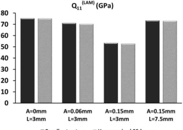
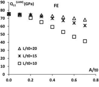
stiffness
Results for CF/EP1 laminate with elastic properties in Table 1 are shown in Figure II-6. Parameters , , are defined in Figure II-3b. In this figure is the thickness of the
31
u ed ⁰-layer, 9 is the a e age thi k ess of the ho oge ized ⁰-layer, ℎ = +
9 . It is clear that � is significantly reduced with increasing amplitude and
decreasing wavelength of the waviness.
Figure II-6. Effect of the waviness on the CF/EP1 NCF composite axial stiffness =
9 ): Using the FE-model in Figure II-3b
One can see very large reduction of � with increasing amplitude and decreasing wavelength of the waviness.
3.3.
Predictions based on isolated curved layers with
boundary conditions used in previous studies
The three curves in Figure II-7 showing the laminate stiffness were obtained using
(II-4). The effe ti e stiff ess of the ⁰-layer − was calculated for isolated curved layer shown in Figure II-4 using FE with boundary conditions (a), (b) and (c). The ⁰-la e effe ti e stiff ess as assu ed e ual to the ⁰-⁰-layer material transverse stiffness using data in Table II-1. These curves may be compared with direct FE results
32
(symbols in Figure II-7) taken from Figure II-6. The comparison demonstrates the failure of these boundary conditions used to give values of 0⁰-layer effective stiffness relevant for using in (II-4).
Figure II-7. Effect of the waviness on the CF/EP1 NCF composite axial stiffness =
9 ): CLT with effective stiffness of the curved layer according to different boundary
conditions
3.4.
The layers effective stiffness dependence on A/t
0 andL/t0
The effective in-plane axial stiffness of the curved layer is lower than the stiffness of a straight layer mainly because the fibres are not oriented in-plane. However, as shown in [23], the effective stiffness strongly depends also on the interaction with the adjacent material (tows of different orientations, resin).
Calculating � according to (II-2) we use the total force which due to force balance is the same in any cross-section. For example, in Figure II-3b =
33
important in which cross-section the reaction force is obtained before dividing it with the average composite thickness ℎ .
If instead the CLT based (II-4) is used, the effective layer stiffness has to be found first. Similarly as was done for the whole laminate stiffness case, we would for this purpose divide the calculated force acting on some arbitrary cross-section of the layer by its section area and then by the applied strain. However, the force on a cross-section of a layer depends on which cross-cross-section we consider. For example
° ≠ ° ° ≠ ° ° + ° = (II-6)
The numbers ° and ° in parenthesis indicate the layer under consideration. Because of Equation (6) effective layer stiffness calculated on the left and the right edge of the model differ
° ≠ ° ° ≠ ° (II-7) where ° = � ° , ° = ° � , ° = 9 ° � 9 , ° = 9 ° � 9 (II-8)
Due to interaction, layers are not subjected to uniaxial loading and strictly speaking the calculated numbers are not stiffness matrix elements. This explains the two different values. The situation will be similar analysing isolated curved layers with traction boundary conditions. Therefore, it has to be clarified which layer stiffness − and
9 − to be used in the CLT (II-4).
For this purpose we may formally write that the force is distributed between 0⁰-layer and 90⁰-layer according to:
34 = ° + ° (II-9) = ° + ° (II-10) And = = (II-11) Averaging gives: = + = 9 ° + 9 ° + ° + ° (II-12) Substituting (II-12) in (II-2) and using (II-8):
� = 9 9 +�9 + 9 9 −�9 9
ℎ +
° + °
ℎ (II-13)
Comparing (II-13) with the CLT expression in (II-4) the correct expressions for effe ti e stiff ess of la e s o side i g the as isolated is gi e :
− = ° + °
(II-14)
9 − = 9 9 +�9 + 9 9 −�9 (II-15)
Forces for using in (II-8) were calculated from the model in Figure II-3b by summing the reaction forces acting on the nodes along the corresponding edge of the layer. The reaction force on the node shared by both layers is replaced by half of the reaction force of the neighbouring node, by analogy with the reaction force on the upper-right node in the free upper boundary, which is also equal to half of the reaction force of its neighbouring node. Figure II-8 sho s ho the effe ti e stiff ess of the ⁰-layer, − a d the effe ti e stiff ess of the ⁰-layer 9 − decrease due to the
35
waviness described by A/t0 for several values of L/t0.The difference between °
and ° calculated on both edges is rather small. In contrast the transverse
effe ti e stiff ess pa a ete s of the ⁰-layer, and have very
different trends: one (calculated at = ) is increasing, the other one is decreasing. The combined effective stiffness 9 − calculated according to (II-15) decreases from about 9 GPa to 7 GPa.
Figure II-8. Axial stiffness for (a) the ⁰-layer and (b) the ⁰-layer, CF/EP1 composite
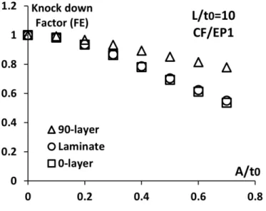
We can introduce knock down factors for the laminate and the layers by dividing the effective stiffness with the stiffness corresponding to a reference case having straight tows (A=0). Figure II-9 shows for CF/EP1 that for L/t0=10 the decrease in composite
36
Figure II-9. Co pa iso et ee k o k do fa to of the ⁰-la e , the ⁰-layer and
the laminate
Apparently the laminate stiff ess edu tio is do i ated the edu tio of the ⁰-layer stiffness due to waviness. A simplified form of the laminate stiffness expression,
(II-4), i hi h the ⁰-la e effe ti e stiff ess is assu ed e ual to the ⁰-layer
material stiffness may be therefore be motivated:
9 − = 9 (II-16)
The accuracy of the simplification in (II-16) will be verified in following calculations.
3.5.
Approximation of tractions at the 0/90-layer interface
In line with the objectives of this study, the task is to find the effective stiffness of the u ed ⁰-layer analysing an isolated curved layer subjected to relevant boundary conditions. These include not only end loads applied to the layer, but also surface loadi g sho as dist i uted load in Figure II-4d. Only in the presence of
37
Knowledge regarding the distributed load is conveniently obtained by analysing st esses at the ⁰- a d the ⁰-layer interface using FE. The results and the observed trends used to define shape functions for the interface stresses from fitting a limited number of FE-calculations are presented in this section. The methodology suggested for finding coefficients in these shape functions is described in more detail in
Appendix. These fu tio s a the e used fo u ed ⁰-layer stiffness analysis with
an arbitrary amplitude or wavelength.
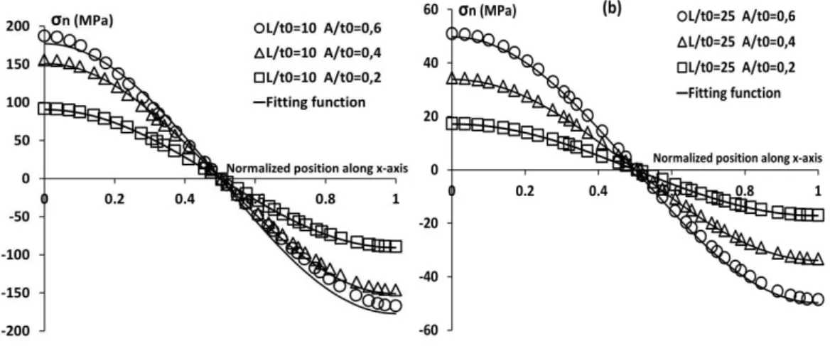
Local stress distribution at the 0/90-layers interface has been analysed: The normal stress � and the shear stress � were determined in each node along a path on the interface. In the FE-analysis those stress components are slightly different on both sides of the interface. The value along the path on the interface which is given by the code is the average of the stresses calculated for the closest element to the interface i the ⁰-la e a d i the ⁰-layer. In Figure II-10, the normal stress � is plotted as a function of the normalized distance along the x-axis for different A/t0 and L/t0. The
curves show large variation of the normal stress along the interface. This stress is equal to zero when there is no waviness. The waviness contributes to the appearance of tensile normal stress in the left part and compressive normal stress in the right part on the interface. The maximum value of the tensile and the compressive normal stress is increasing with decreasing L/t0 and with increasing A/t0. For simplicity, this behaviour
was fitted with a sinusoidal function, (II-17), with amplitude depending on the waviness parameters and the elastic properties of the material.
38
Figure II-10. Normal stresses at layer interface in CF/EP1 composite and fitting (a) for L/t0=10; (b) for L/t0=25, applied strain 1%.
In Figure II-11, the shear stress � on the interface is plotted as a function of the normalized position along the x-axis for different A/t0 and L/t0. In a straight layer
cross-ply laminate this stress component would be equal to zero. However, the rather complex � eha io e o es sig ifi a t ith i easi g ⁰-layer amplitude. Calculations on isolated curved layers showed that the significance of the applied shear stress on the boundary is small (most important is the normal stress � ), justifying the use of the same rough sinus function approximation to fit the shear stress in the whole parameter region
� = � � ( − ) = −� ( ) (II-18)
� ℎ � = ( , , , )
As one can see in Figure II-11a the fitting is obviously not good for small L/t0 and
39
Figure II-11. Shear stresses at layer interface in CF/EP1 composite and fitting (a) for L/t0=10; (b) for L/t0=25, applied strain 1%.
Thus, performing FE-calculations for a limited number of L/t0 and A/t0 cases we can
find approximate interface stress expressions for a given material to be used for any practical combination of these geometrical parameters.
The main objective of this part was to find simple expressions for further analytical application. The expressions for � and � dependence on L/t0 and A/t0 are given in
Appendix.
3.6.
Composite stiffness based on effective stiffness of an
isolated 0
⁰-layer with surface loads
In this subsection we use the calculated and approximated normal and shear stress distributions along the layer interface as surface loads in a isolated u ed ⁰-layer model shown in Figure II-12. The approximate expressions for the normal and the shear stresses given in Appendix are used. The surface load is obtained by multiplying the stress components by the element length which is assumed equal to the distance
40
dx between two neighbouring nodes. The calculated load is applied in the local coordinate system related to each element on the bottom surface of the curved layer. This new boundary condition is introduced in addition to the symmetry on the left edge and the displacement applied in the right edge. Since the loading applied to the ⁰-layer is not uniaxial the − calculated using (II-14) is, strictly speaking, not the a ial stiff ess. Ne e theless, it ep ese ts the u ed ⁰-layer mechanical behaviour in the composite.
Figure II-12. Appli atio of dist i uted load o the ⁰-layer surface
In Figure II-13, he e the al ulated effe ti e stiff ess of a isolated ⁰-layer is p ese ted togethe ith the effe ti e stiff ess of the ⁰-layer determined from the waved cross ply laminate, see Section2.4 “The layers effective stiffness dependence on A/t0 and L/t0”, good agreement between both solutions is demonstrated. For the
sake of o pa iso , effe ti e ⁰-layer stiffness calculated using the rest of boundary conditions in Figure II-4 is also presented. Effective stiffness in the case of fixed/free ends is unrealistically low, while rigid foundation is too high. The most accurate results are given by the beam with distributed surface load. Thus, the assumption of replacing the i te a tio et ee the ⁰ a d the ⁰-layers in the laminate by a distributed load
41
applied to the curved beam is validated. The accuracy can be improved by more accurate fitting of the interface stresses; the simplicity can be improved by more rough approximation that, probably, would not affect the calculated stiffness too much.
Figure II-13. Effe ti e stiff ess of the ⁰-layer with different boundary conditions
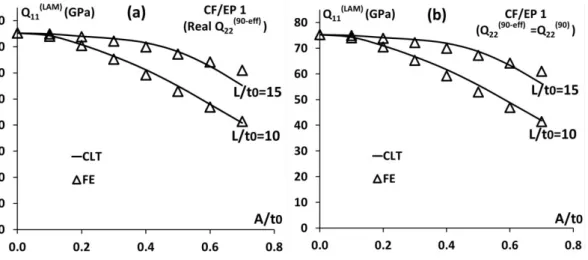
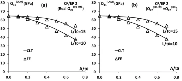
Finally, CLT, see (II-4), is used to determine the laminate stiffness utilizing the effective stiff ess of the u ed ⁰-layer with distributed load, and the effective stiffness of the ⁰-la e . Effe ti e ⁰-layer stiffness is used in two approximations: a) With varying thickness with values from Figure II-8b (this requires FE calculations of the cross-ply composite); b) using (II-16), i.e. 9 − = 9 (which is not accurate, but simple for use). In Figure II-14 to Figure II-16 the laminate stiffness is presented as a function of
A/t0 for different L/t0. In Figure II-14a, II-15a and II-16a the effective stiffness of the
⁰-layer is used whereas in Figures II-14b, II-15b and II-16b the ⁰-layer with varying thickness is represented by its transverse stiffness 9 calculated using data in
Table II-1.These results show good agreement between the analytical CLT approach
42
Ve s all diffe e es i esults a e see he the ⁰-layer effective stiffness is represented by its material transverse stiffness, proving that this approximation may be used.
Figure II-14. CLT using effective stiffness compared to FE-analysis for CF/EP1
![Figure I-11. Examples of whole cracks running through two neighbouring 90°fibre bundles of the cross-ply NCF laminate [29]](https://thumb-eu.123doks.com/thumbv2/123doknet/15050604.694844/35.892.229.718.103.321/figure-examples-cracks-running-neighbouring-fibre-bundles-laminate.webp)
![Figure I-13. Examples of double cracks in single 90° fibre bundles of the cross-ply NCF laminate [29]](https://thumb-eu.123doks.com/thumbv2/123doknet/15050604.694844/36.892.236.709.104.311/figure-examples-double-cracks-single-fibre-bundles-laminate.webp)