BUSINESS EXPANSION AND LEAN TRANSFORMATION FOR HELICOPTER BLADE SHOP
by
S. Neil Bar
B.S. Mechanical Engineering, Columbia University, 1999
Submitted to the Sloan School of Management and the Department of Mechanical Engineering in partial fulfillment of the requirements for the degrees of
Master of Business Administration
AND
Master of Science in Mechanical Engineering
In conjunction with the Leaders for Manufacturing Program at the Massachusetts Institute of Technology
June 2006
0 Massachusetts Institute of Technology, 2006. All rights reserved.
S ign atu re o f A u th or M ay 2 00 6
May 2006 MIT Sloan School of Management Department of Mechanical Engineering Certified by
D iel Whitney, Thesis Advisor Senior Research Scientist Center for Technology, Policy pd Industrial Development Certified by
RoVelsch, Thesis Advisor Professor of Statistics and Management Science Center for Computational Research inc,,nomics and M)iagementJcience Accepted by
/ Debbie Berechman Director of Masters Program SloapSchool of Management Accepted by________________
Professor Lallit Anand Chairman, Graduate Committee MASSACHUSETTS INSTMIUTE Department of Mechanical Engineering
OF TECHNOLOGY
BUSINESS EXPANSION AND LEAN TRANSFORMATION FOR HELICOPTER BLADE SHOP
by S. Neil Bar
Submitted to the Sloan School of Management and the Department of Mechanical Engineering on May 10, 2006 in Partial Fulfillment of the Requirements for the Degrees of Master of Business Administration and Master of Science in Mechanical Engineering ABSTRACT
Sikorsky Aircraft is undergoing a lean transformation as its helicopter blade line is relocated from Stratford to Site B. Value Stream Mapping is a vital tool to eliminate sources of waste in the existing blade shop and to create a vision for the future state production system. This thesis briefly focuses on the enterprise to provide a sound understanding of the business and aerospace industry, describing the flow of information from customer proposal through product delivery. Detailed value stream maps for the main and tail rotor blades are then analyzed from an operations perspective to uncover major time and process delays.
Implementation is a topic of in-depth review within this thesis. As a management tool, Value Stream Mapping does not reinforce roles, responsibilities, and accountability to achieve the future state vision. Therefore, a set of guidelines are followed to coordinate kaizen initiatives. Examples consist of matrices to quantify and prioritize opportunities, charters to organize teams and deliverables, and work plans to track progress and metrics. The introduction of management tools aid in satisfying monthly throughput targets while establishing a precedence for upcoming lean programs.
The thesis concludes with the design of a lean production system, which includes a new cellular layout. The future operating system is intended to align Sikorsky's lean flow philosophy with manufacturing capabilities. Recommendations to further enhance factory operations are evaluated in the final chapters along with an action list for on-going projects. A wrap-up for sustaining change is also discussed through a formal critique of the management organization.
Thesis Advisor: Daniel Whitney Senior Research Scientist
Center for Technology, Policy and Industrial Development Thesis Advisor: Roy Welsch
Professor of Statistics and Management Science
ACKNOWLEDGMENTS
I would like to extend my appreciation to the Leaders for Manufacturing Program, the Sloan School of Management, and the School of Mechanical Engineering for their
support of my work. Through MIT, I had a wonderful opportunity over the two years to learn from faculty and diverse classmates. I would like to specifically thank my advisors: Daniel Whitney of the Center for Technology, Policy and Industrial Development, and Roy Welsch of the Center for Computational Research in Economics and Management Science.
I would like to acknowledge Sikorsky Aircraft for sponsoring my internship. Many thanks to Neil Crockett, Larry Donohue, Ed Machia, Sue Burzynski, Doug Walker, and the entire operations organization for providing a great experience. My internship would not have been a success without their guidance and knowledge.
A special thanks also goes to Arnie Appleby, Bob Mahmood, Lori James, Bob Smith, and all the line operators for helping me navigate the factory and answering even the simplest of questions to further my understanding of blade manufacturing processes.
Finally, I would like to express my appreciation to my family for their encouragement and faith in me. I hope that I fulfilled your dreams and made you proud.
TABLE OF CONTENTS
CHAPTER 1: INTRODUCTION...11
1.1 Background of United Technologies and Sikorsky Aircraft...11
1.2 Lean Manufacturing at Sikorsky...14
1.3 Thesis Structure...15
CHAPTER 2: PROBLEM STATEMENT AND DISCUSSION...17
2.1 Project Motivation...17
2.2 Short-Course in Rotor Blade Manufacturing...17
2.3 Goals, Scope, and Approach...20
2.4 Key Ideas and Hypotheses...22
2.5 Chapter 2 Summary...22
CHAPTER 3: KEY CONCEPTS AND LITERATURE REVIEW...25
3.1 Mass Production Loses Steam...25
3.2 The Birth of Lean Production...25
3.3 Value Specification and Identification...26
3.4 Creation of Flow...27
3.4.1 D esign ... 27
3.4.2 Order-Processing...27
3.4.3 Production...28
3.4.3.1 Manufacturing and Assembly Cells...28
3.4.3.2 Setup Tim es...29
3.4.3.3 Quality and Preventative Maintenance...29
3.4.3.4 Level and Balance...30
3.5 Pulling Product...31
3.6 Perfection... 3 1 3.7 Lean in the Blade Shop ... 31
CHAPTER 4: THE ENTERPRISE PERSPECTIVE...33
4.1 Contracts and Pricing...33
4.2 Blade Engineering...34
4.3 Purchasing...35
4.4 Planning and Control...35
4.5 Enterprise Summary...36
CHAPTER 5: VALUE STREAM MAPPING AT SIKORSKY AIRCRAFT...39
5.1 E lim inating W aste...39
5.2 Creating Value Stream Maps...40
5.3 Inter-Plant Overview - K200 Main Blade...40
5.4 Current State - K200 Main Blade...41
5.5 Future State Vision - K200 Main Blade...42
5.6 K200 Tail Blade...45
CHAPTER 6: IMPLEMENTATION OF KAIZEN INITIATIVES...47
6.1 Prioritizing Kaizen Events...48
6.2 The Site B Challenge...50
6.3 Chartering Teams...52
6.4 Project B - Work Planning and Metrics...53
6.5 Auditing...57
6.6 Chapter 6 Summary...58
CHAPTER 7: ACHIEVING PHASE III...59
7.1 Cellular Arrangement...59
7.2 Simulation Modeling...61
7.3 Discussion...63
7.4 Recommendations...65
CHAPTER 8: SUSTAINING AND CONTINUING CHANGE...67
8.1 Project Background and Description...67
8.2 Three Perspectives on Organizational Processes...69
8.2.1 Strategic Design...69
8.2.2 Political Landscape...70
8.2 .3 C ulture...7 1 8.3 Evaluation and Recommendations...72
APPENDIX A: VALUE STREAM MAPS A.1 Main Blade Current State...73
A.2 Tail Blade Current State...87
A.3 Tail Blade Future State...98
APPENDIX B: VALUE STREAM MAPPING SYMBOLS...99
Figure Figure Figure Figure Figure Figure Figure Figure Figure 1 Figure 1 Figure I Figure 1 Figure I Figure 1 Figure 1 Figure 1 Figure 1 Figure 1 Figure 2 Figure 2 Figure 2 Figure 2 Figure 2 Figure 2 Figure 2 Figure 2 LIST 0 Table 1. Table 2. Table 3. Table 4. Table 5. Table 6.
2. Market Segments and Product Portfolio 3. Composite Spar for Main Rotor Blade
4. Main Blade Clamshell 5. Main Blade Root End
6. Main Blade Attachment to Cuff 7. Isometric View of Main Blade
8. Breaking Cross-Functional Boundaries
9. Single Piece Flow Cells by Product Family 0. Simple Illustration Exemplifying Heijunka
1. Rough MRP Illustration for Blade Fabrication 2. Dissecting and Interpreting Waste
3. Inter-Plant Value Stream Map for K200 Main Blade 4. Future State Map for K200 Main Blade
5. Value Stream Improvement Process
6. Site B Factory - Phase II Layout (Not to Scale) 7. Main Blade Value Stream Team Charter for Project B 8. Partial Time Study for Process 1 of Spar Fabrication
9. K200 Monthly Throughput
). K200 Main Blade Cellular Layout for Site B
I. One-Month Production Simulation 2. One-Quarter Production Simulation
3. Revised Hypothetical Future State Map for K200 Mai 4. Shift from Series to Parallel Processing
5. Simplifying Bottlenecks in Final Assembly 5. Enterprise Versus Department Level Lean
7. Project Stakeholder Map
F TABLES
K200 Goal Document Kaizen Prioritization Matrix
Initial Shift Loading Chart for K200 Spar
Modified Shift Loading Chart Due to Demand Spike Orientation of Processes for K200 Future State K200 Main Blade Capacity Analysis
n Blade LIST OF FIGURES
Chapter 1: Background and Introduction
Located in Stratford, Connecticut, Sikorsky Aircraft aspires to become the first name of choice in vertical flight. The company, a longstanding division of United
Technologies Corporation, has been immersed in an operations transformation after the turn of the century. Such an endeavor led by Chairman and CEO, George David, can be characterized as a business-wide strategy to increase operating margin and inventory turns across all existing factories.
Since the early 1990s, the aerospace industry has been confronted with demand uncertainty and steep pricing pressure, giving way to a bleak competitive landscape. As a result, manufacturers and vendors must minimize lead time and inventory levels by fine-tuning production and supply chain activities. Doing so requires a sound understanding and ability to apply lean manufacturing techniques, which serve as a foundation for UTC's operations transformation. The methodology has been a key contributor towards sustained growth in a volatile economy. Rigorous implementation is therefore a
necessity to Sikorsky's continued success.
In this chapter, an overview of United Technologies and Sikorsky Aircraft is provided, including a brief history of lean applications in helicopter manufacturing. Although lean practices were brought into UTC during the 1980s in part by Pratt & Whitney, a comprehensive program was not instituted company-wide until two decades later. Chapter 1 concludes with a general outline of this thesis.
1.1 Background of United Technologies and Sikorsky Aircraft
Named the most admired aerospace company for five consecutive years, United Technologies is a diversified industrial firm headquartered in Hartford, Connecticut with 2005 revenues of $37 Billion. Globally represented in over 62 countries, UTC has a reputation for pioneering innovation in aerospace, aviation, helicopter design, climate control, elevator design, and hydrogen fuel cells. Eight independent business units comprising the corporation are summarized below:
* Carrier Heating and Air Conditioning * UTC Fire & Security Protection Services
* Hamilton Sunstrand Aerospace and Industrial Systems * Otis Elevators and Escalators
* Sikorsky Aircraft
* Pratt & Whitney Aircraft Engines * UTC Power
* United Technologies Research Center
The majority of these subsidiaries share a unique and common bond in that they were founded by the original product inventors.
Sikorsky Aircraft traces its legacy to 1939 when Igor Sikorsky developed and flew the first practical and stable helicopter that could remain airborne for 15 minutes at a time. The VS-300 was a simple machine composed of steel tubing, open cockpit, a 65-horsepower engine, and a belt transmission turning a 3-bladed main rotor. Over the past 65 years, the company has become a world leader in the design and manufacture of advanced helicopters for commercial, industrial, and military applications with major
facilities in Connecticut, Florida, Alabama, and Wisconsin.
From a military standpoint, Sikorsky helicopters currently serve roughly 50% of all five branches of the United States armed forces. The Blackhawk and its derivatives continue to remain the core company product, flying various missions for the Army, Air Force, and Marine Corps. Additionally, the company manufactures the Seahawk for the Navy and the Jayhawk for the Coast Guard. Finally, Sikorsky supplies the heavy-lift
CH-53 to the Air Force, Navy, and Marine Corps for use in anti-mine warfare and personnel/equipment transport.
In the commercial and industrial arena, Sikorsky provides two types of helicopters. The S-76 is widely flown in 40 countries for executive travel, offshore oil, emergency medical service, and airline missions. The company's civil aircraft line-up also encompasses the S-92, capable of carrying up to 22 passengers per load. See Figure 2 below for an illustration of Sikorsky's general product classification.
-=-- . ----K !- - . -.. .. j - . - .r - - ;-N-Product Category Blackhawk Seahawk Jayhawk CH-53 H-92 S-76 S-92 Military-Commercial Industrial
Like its sister company Pratt & Whitney, Sikorsky complements its products with a diverse array of aftermarket services designed to minimize operator downtime, improve usability, and reduce cost of ownership. Helicopter Support Incorporated (HSI) is an
independent subsidiary that tends to the needs of commercial operators, offering a full range of factory-authorized services. On the military side, Sikorsky acquired Derco Holding, which is a leader in aircraft logistics, component distribution, repairs, and aftermarket program management. The alliance fostered between HSI and Derco combines the strength of a major manufacturer with the flexibility of a small company.
1.2 Lean Manufacturing at Sikorsky Aircraft
American companies during the post war period, extending into the 1980s, had an inclination to emphasize products over processes, ultimately laying the groundwork for economies of scale and standardized products. UTC has parted ways with this norm and embarked on a lean journey, leading a revolution to integrate Japanese production
techniques for dramatic process improvements. George David described the mental shift as follows:
"We treated setup times as fixed and established lot sizes accordingly; Japanese methodology eliminated setup times and costs. We drove the manufacturing process by push, relying on extremely complicated scheduling systems; Japanese processes stressed kanban scheduling. We relied on end of line inspection; Japanese practice sought process control at each individual station, working to a philosophy of never building bad product in the first place, and therefore eliminating inspections entirely; We treated our suppliers as adversaries, seeking to maximize our gains at their expense; Japanese methodology sought integration among suppliers and customers, generating value for both parties by doing things better together" (David, 1999).
The ACE (Achieving Competitive Excellence) Program, created by United
Technologies in the early 1990s, was the first legitimate effort towards enhancing quality across the business. The initiative itself is not quite lean manufacturing in its purest
form. Common lean principles such as specifying and identifying value, creating flow, and using kanban systems are missing from ACE. However, the toolkit reinforces
continuous improvement through 6-sigma with elements of 5S, total productive
maintenance, root cause analysis, mistake proofing, standard work, and setup reduction. As mentioned earlier, United Technologies has instituted a broader undertaking termed "Operations Transformation." The program is geared towards increasing operating margins by addressing challenges in four areas: strategic sourcing, low-cost sourcing, design for manufacturability, and leadership. A fifth component of Operations Transformation, Value Stream Mapping (VSM), has been coupled with ACE to
strengthen Sikorsky's lean capabilities.
1.3 Thesis Structure
The organization of this thesis is outlined below:
Chapter 1: A brief overview of United Technologies and Sikorsky Aircraft has been provided. The industry environment, corporate history, product classes, and
events leading to lean transformation serve as a suitable primer to understand the project framework.
Chapter 2: The motivating force behind the internship as well as the goals, objectives, and hypotheses are covered. A basic approach to identify, analyze, and resolve the critical issues is also revealed.
Chapter 3: This chapter describes traditional elements of lean manufacturing and their application in the helicopter blade shop. A literature review on lean implementations by previous LFM students is included.
Chapter 4: The core of this thesis begins with an enterprise perspective. Chapter 4 essentially captures the informational flow across the business value stream from contract authorization to new product release.
Chapter 5: Chapter 5 transitions to a department level analysis with a deep-dive into rotor blade operations to illustrate product flow through the factory. The value stream maps are used to identify sources of waste in the production process. Chapter 6: This chapter focuses on the key factors attributed to long lead times and poor
monthly blade deliveries. Tools to quantify, prioritize, and implement improvement initiatives are discussed in chapter 6.
Chapter 7: New territory is explored with a future state layout of the factory. In this chapter, a one-piece flow system in a cellular arrangement is proposed and validated through a simulation software package (SIMUL8).
Chapter 8: The final chapter concludes with an evaluation of Sikorsky's management organization and potential plans for sustaining change in a dynamic business. Appendix A: Current state maps for the main and tail rotor blades document the
individual processes, inventory locations, and value-added manufacturing times.
Appendix B: This thesis is written under the assumption that its readers have at least a beginner level knowledge of lean manufacturing philosophy. Data will be
evaluated and conclusions shall be drawn where appropriate to aid in the reader's understanding of the material. However, the thesis alone is not thorough enough to sufficiently explain the icons specifically applied in value stream mapping. Although Appendix B contains a legend with symbol descriptions, the workbook Learning to See (Rother and Shook, 1999) is a better resource.
Chapter 2: Problem Statement and Discussion
This chapter presents an introduction to the challenges confronted by Sikorsky Aircraft and the motivation behind the internship. A concise lesson in blade
manufacturing practices will shed ample light on the project objectives and methodology to address critical issues observed in the factory. The end of chapter 2 outlines the underlying hypotheses guiding this research.
2.1 Project Motivation
Sikorsky is expecting a doubling in business volume over the next 3 years. Once a vertically integrated company, Sikorsky has revised its strategy by shifting non-core manufacturing to the supply base and transforming batch and queue process villages into lean flow lines. Choosing a low cost, high profit operating model has influenced
Sikorsky's decision to concentrate on key competencies, including parts manufacturing. Given an aggressive demand setting for upgraded aircraft and spares, the parts manufacturing organization is under pressure. Sikorsky must free up factory floor space to accommodate its growing production requirements. To execute this task, the company is transferring the main and tail rotor blade lines for the K200 helicopter to Site B. To maintain confidentiality, the specific site and aircraft model have been masked. With K200 orders on the rise, Sikorsky plans to accelerate blade production in the third quarter to ensure aircraft delivery and avoid contract penalties. Thus, the purpose of the
internship is to assist in the relocation, improve throughput at Site B with a temporary plant layout, and propose a lean factory re-design for future main blade operations.
2.2 Short-Course in Rotor Blade Manufacturing
In order to fully grasp the internship direction embedded within Sikorsky's lean transformation effort, the reader should possess a rudimentary knowledge of how composite rotor blades are constructed by industry players. A main blade is typically manufactured in two progressive stages, which are listed as follows:
1. Spar Fabrication 2. Blade Assembly
The spar, or skeleton of the blade, is a composite made up of several layers of
textured graphite and glass ply kits. In their collective arrangement, these plies are more
advanced and environmentally friendly than titanium, maintaining greater flexibility and
requiring little finishing treatment. The disadvantage, however, is that composites are
susceptible to defects related to air gaps between successive layers of plies. Figure 3
depicts a spar that is formed around a fixture for its oval shape.
SIDE VIEW
Figure 3. Composite Spar for Main Rotor Blade
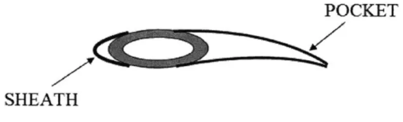
During blade assembly, material is compacted onto the spar and cured in a large
autoclave. The pocket, composed of a skin with honeycomb core, is primed and bonded
to the spar's trailing edge. Counterweights are then mounted to the opposing end of the
spar and enclosed by a sheath stretching over the leading edge. The sheath essentially
releases heat as a de-icer element and contains a combination of materials including
nickel, titanium, and fiberglass. Figure 4 shows the spar progressing towards an
aerodynamic profile.
SHEATH
Figure 4. Main Blade Clamshell
After the pocket and sheath are applied, the main blade assembly proceeds to
laminate bond, where it receives additional composite layers for strength under dynamic
loading conditions. The purpose of this operation is to alleviate high stresses occurring at
the root end near the helicopter rotor head. The next step involves milling and drilling
ROOTEND * TIPEND
Figure 5. Main Blade Root End
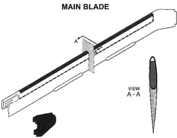
In the finals station, manual detail work is completed on the tip and root ends. The cuff, an interfacing component that connects to the helicopter rotor head, is then fastened to the main blade. Similar to a spar, the cuff is also constructed from layered composites. Figure 6 demonstrates how the main blade and cuff are joined together.
Figure 6. Main Blade Attachment to Cuff
Once complete, the entire assembly is passed on to paint and finishing for a durable coating. Before releasing a main blade to the hangar or spares customer, it is balanced and tested on a whirl stand. See Figure 7 for a view of the completed product.
MAIN BLADE
Figure 7. Isometric View of Main Blade
Tail blade manufacturing is slightly different from that of a main blade. While the main blade contains a spar, the tail blade consists of a torque tube similar in material and shape, but much smaller in scale. Instead of using a cuff, technicians install a slender beam to join the blade to the aircraft. The tail blade is also robust in that it does not require a laminate bond.
2.3 Goals, Scope, and Approach
Fabrication for the K200 helicopter commenced in 2004 and transformation of the rotor blade lines followed shortly afterwards. In one year, Sikorsky progressed rapidly along a sharp learning curve to satisfy customer needs and categorized its lean execution into three major stages:
Phase I -Relocate all K200 production equipment to Site B.
Phase II -Establish a temporary layout around existing monuments. Phase III -Implement cellular arrangement with in-line machines.
This research hinges on three aspects of lean methodology: enterprise and department
level value stream mapping, management of improvement initiatives, and the design of a
dedicated lean flow line for main rotor blades.
Deliverable 1
Value Stream Mapping is employed during Phase II to assess the current state of the
main and tail blade production systems. However, before analyzing material flow, it is
important to step back and observe how factory processes fit into the overall context of
the business. For example, the purchasing organization may be optimized as a
stand-alone department, but could be considered sub-optimal if the total enterprise is not lean
(Figure 8). That is why documenting information flow across various cross-functional
areas provides a valuable frame of reference.
Contracts and Pricing
Engineering
Total Lean Enterprise Purchasing
Lean Department Planning and Control
Figure 8. Breaking Cross-Functional Boundaries
Deliverable 2
Using future state value stream maps, several potential kaizen events are identified to
reduce lead time and increase monthly blade deliveries. However, as a management tool,
value stream mapping by itself does not emphasize team roles, responsibilities, and
actions needed to achieve an ideal production system. Therefore, specific guidelines are
applied to prioritize the activities, track performance, and audit the changes.
Deliverable 3
Long lead times and poor throughput levels have been logged throughout Phase II. With orders expected to double by 2006, Phase III capital investment plans are under review to ensure that the plant can adequately accommodate the volume. Although most expenditures have been approved, a cellular arrangement will not be finalized within the scope of the internship. Despite the timing issue, a proposed factory layout for the main rotor blade is presented. The challenge in designing a lean flow line becomes evident given the physical constraints of the Site B plant.. A discrete event simulation is included to validate the new manufacturing cell.
2.4 Key Ideas and Hypotheses
In certain instances, companies apply lean to rectify individual processes. While locally patching the problem offers some relief, the result is often times temporary or
even negligible over the long haul. Introducing a sustainable solution means that the whole value chain must be examined as a complete entity. One hypothesis of this research is that the presence of "fat" in the upstream activities places pressure on
downstream operations. Value Stream Mapping is an excellent tool to detect waste and establish a future vision of the enterprise.
Many production facilities are historic behemoths developed around mass production principles. However, in light of aggressive competition, manufacturers are embracing
lean methodology to reduce costs, enhance quality, and accelerate responsiveness to changing customer demands. The disposal of batch and queue processing has brought about greater agility in the market. A second supporting hypothesis is that the
introduction of flow in a brownfield site can significantly boost operating metrics and dramatically reduce space requirements. But, a full system redesign is necessary to realize the plant's true potential and benefits of lean.
2.5 Chapter 2 Summary
Throughout chapter 2, we touched upon the motivating factors for the internship, an introductory course to rotor blade fabrication, and the hypotheses guiding the author's project objectives. In Chapter 3, relevant lean terms and concepts are introduced to
provide a flavor for twenty-first century manufacturing challenges. Some of the tools from this discussion are selectively applied in the later chapters to address the
Chapter 3: Key Concepts and Literature Review 3.1 Mass Production Loses Steam
Similar to Henry Ford and the mass production concepts employed under his supervision, many organizations operating in various industries prospered during the early 1900s utilizing identical techniques. Prominent breakthroughs included interchangeability of parts, standard work sequences, and the moving assembly line. However, in the latter half of the twentieth century, mass production fell short of meeting the customer need.
First and foremost, unions despised the repetitive nature of the job and sought to minimize working hours, which indicated a strained partnership between management and its people. Secondly, companies purchased larger equipment to support scale economies, eventually leading to batch production, huge work-in-progress, and soaring finished goods inventories. Quality was directly impacted as operators became less involved, allowing defects to duplicate in any given batch before being detected. Under this reactive system, end-of-line inspection stations were common as completed products were removed for repairs. Lastly, engineers branched into specialized departments in response to the growing complexity of products. The lack in communication not only introduced design problems, but also lengthened overall time to market.
3.2 The Birth of Lean Production
If mass production ideology proved inadequate as mentioned in the previous section, then what type of system would satisfy a diverse customer base? The corporate building blocks, mainly people and machines, must be aligned such that the output (Dennis, 2002):
* Is defect-free with the features and performance the customer expects " Can be delivered one request at a time (batch size of 1)
* Can be supplied on demand in the version requested * Can be delivered immediately
" Can be produced without wasting any materials, labor, energy, or other resources (such as costs associated with inventory)
" Can be produced in a work environment that is safe physically, emotionally, and professionally for every employee
This definition is a founding principle of lean manufacturing, where better performance can be expected with less time, effort, equipment, and space. Instituted by Taiichi Ohno
and Eiji Toyoda in the 1950s, the Toyota Production System (TPS) was developed and refined to address the driving forces behind today's global challenges: fragmented markets demanding several low-volume products, rapidly changing technology, tough competition, fixed or falling prices, high cost of capital, and greater worker involvement (Dennis, 2002).
Over the past five decades, the Toyota Production System has been perceived more as a "way of thinking" rather than a "list of things to do." Until recently, the tools had rarely been articulated in writing, making it difficult for outside firms to grasp. Although
several books currently exist to describe specific TPS practices in isolated pieces, Jim Womack and Dan Jones co-authored a text in 1996 that ties all the methods together into
a cohesive implementation guide. Based on their extensive research, lean thinking can be summarized in five steps, which will be discussed further in the following sections: precisely specify value by specific product, identify the value stream for each product,
make valueflow without interruptions, let the customer pull value from the producer, and pursue perfection (Womack and Jones, 1996).
3.3 Value Specification and Identification
Lean thinking establishes a complementary relationship between producers and consumers. It must begin with a value proposition that can only be defined according to the end customer. A producer, on the other hand, creates value for the sole purpose of providing a good or service which meets the customer need at a specific price and time.
Identifying the value stream exposes value-creating activities as designs progress from concept to launch, information flows from initial order to delivery, and physical product moves from raw material to customer. Doing so reveals three types of processes along the value stream (Dennis, 2002):
1. Actual Work: Refers to actions that add value to the good or service (i.e. installing a blade on a helicopter rotor head)
2. Auxiliary Work: Unavoidable action supporting actual work (i.e. selecting a blade from storage)
3. Muda: Opposite of value; Any action for which the customer is unwilling to pay (i.e. making more parts than customer demands)
Techniques for value stream mapping and categorizing sources of waste in the blade shop will be covered in Chapter 5.
3.4 Creation of Flow
Creating continuous flow is the second phase in lean transformation and most likely the hardest since today's leaders are evaluated based on their adherence to existing measurement systems. Organizing work into vital steps with no interruptions, excess motion, batches, or queues can have a dramatic effect on operations. But, successfully applying flow calls for managers to challenge the deep-rooted assumptions, obsolete models, and traditional indicators of efficient production.
3.4.1 Design
Product design has always been a batch-and-queue process where work is handed off from one department to another. The marketers translate the voice of the customer to designers who develop a good. After a design is complete, buyers purchase certain parts and arrange delivery from the supplier base. Finally, manufacturing engineers consider tooling and factory requirements to fabricate and assemble components. While this format would suffice for a single initiative, ownership issues surface when
simultaneously driving multiple platforms. If something is everyone's problem, it becomes nobody's problem (Spear and Bowen, 1999).
The lean solution is to appoint dedicated product teams with keen proficiency in value specification, design engineering, purchasing, tooling, and production planning.
This specialized approach is more responsive, allowing teams to execute with limited rework and effectively transition products from concept to customer.
3.4.2 Order-Processing
Historically, the sales force has taken responsibility for independently securing business from retailers. Once orders are cleared, the information is relayed to the
scheduling department which in turn communicates relative ship dates to the customer. If a particular delivery is late, scheduling personnel expedites the request by manually moving idle parts to the front of the queue where they can be immediately assembled.
Repeating this cycle compromises the customer relationship by increasing overall wait time for prior orders.
In a lean environment, the sales and scheduling functions are critical members of the product team, where both parties share a mutual knowledge of production capabilities. Generating a strong sales plan ensures that information contained in each unique order can flow alongside its respective product from sale to delivery. A key to achieving such consistency is the notion of takt time, which synchronizes the rate of production to that of demand. The term will be further explained in chapter 6.
3.4.3 Production
Since the introduction of lean philosophy to American culture, the production setting has received much attention. Even before Jim Womack and Dan Jones published Lean Thinking, J.T. Black wrote The Design of the Factory with a Future in 1991, chronicling the efforts of companies to incorporate critical elements of the Toyota Production System. In his book, Black outlines ten steps to create an Integrated Manufacturing Production System (IMPS), half of which address flow methodology and coincide with Just-in-Time (JIT) innovation pioneered at Toyota in the 1950s (Black, 1991).
3.4.3.1 Manufacturing and Assembly Cells
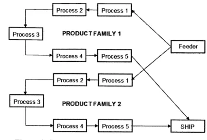
In a continuous flow scenario, manufacturing cells should be arranged as a group of sequential fabrication steps with one-piece movement of parts and no buffer of work-in-process. Equally important, the cells must be organized by product family and contain right-sized machines that can fit directly into the production line. See Figure 9 for an
Process 2 FlProcess 1
Process 3 PRODUC T FAMILY 1
Feeder
Process 4
H
Process 5 Process 2 +-Process 1 Process 3 PRODUC TFAMILY 2-- Process 4 Pro ce ss 5 SHIP
Figure 9. Single Piece Flow Cells by Product Family
The diagram shows greater flexibility because storage disappears, work teams can be adjusted in size depending on cell volumes, and larger machines that were once central to all products are now dedicated to individual families.
3.4.3.2 Setup Times
In a technologically advancing society, many customers demand tailored goods at a price comparable to large volume production and lead time of "instant availability." Thus, providing mixed models without adding changeover time is crucial if companies expect to meet customer needs. Quick changeovers also enable manufacturers to alleviate bottlenecks, lower costs, and improve quality. But, bear in mind, the end objective of flow thinking is to totally eliminate all stoppages in an entire production process (Rother and Harris, 2001).
While Taiichi Ohno had completed some setup reduction at Toyota, Shigeo Shingo revolutionized the factory by developing an approach known as Single Minute Exchange of Dies (SMED). Through his teachings, companies have utilized the methodology to uncover its benefits, cutting changeover times from hours to just minutes (Shingo, 1985).
3.4.3.3 Quality and Preventative Maintenance
The third and fourth steps in creating flow are to integrate quality and preventative maintenance within the cell. In a lean operation, tasks are standardized such that employees assemble every component correctly on the first attempt. Even more so, it
becomes vitally important that workers feel empowered to monitor their own work as
products move downstream. This can be aided through an inspection technique called
poka-yoke, or mistake-proofing, which applies visual control to prevent defective parts
from proceeding to subsequent stages (Womack and Jones, 1996). For example, a part
with two similar sized holes may be difficult for an operator to distinguish during
assembly. However, placing a notch or letter "L" next to the larger hole eliminates
potential confusion.
3.4.3.4
Level and Balance
Companies embracing a lean culture strive to facilitate one-piece flow in the factory,
but often build to order with a "speed up, slow down" strategy. The monthly variation in
demand generates an uneven schedule that encourages operations planners to switch
between making substantial and minimal quantities from week to week. While customers
are unpredictable, this production mentality fosters high inventory level and poor quality.
More importantly, it leads to mismanagement of resources and complicates upstream
supplier interactions.
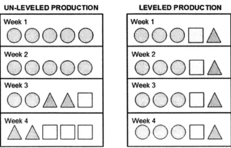
Black's fifth step in regulating flow is to level the work schedule by volume and
model mix, otherwise known as heijunka according to Toyota philosophy. Those who
employ heijunjka do not build product based on actual customer demand. Instead, they
take the total volume of orders in a given period and balance them so that the same
amount and mix can be made every day. Figure 10 represents basic shapes as mixed
models and visually clarifies un-leveled versus leveled conditions.
UN-LEVELED PRODUCTION LEVELED PRODUCTION
Week 1 Week 1
0000
OQOL
0A
Week 2 Week 200000
OQOLA_
Week 3 Week 3OOAAO
OOIA
Week 4 Week 4AAIDEII
OODOA
3.5 Pulling Product
Although any company can apply the framework in Section 3.4 to initiate faster flow in a factory, how does one assure that the right goods are provided at the appropriate time and in the correct amount? The third phase in lean implementation is pull production, which means that nobody upstream should produce an item unless the downstream customer requests it. Communication between downstream and upstream processes usually takes the form of a pull signal, or kanban.
A kanban system maintains an orderly and efficient flow of material across the entire manufacturing chain. It primarily relies on the movement of parts through the use of cards and containers. With this tool, the supplier (or warehouse in some cases) should deliver components to work stations only when they are required. Conversely, each station must only produce when a card and empty bin is received, indicating a need for more components.
3.6 Perfection
The final phase in creating a lean factory is perfection, where business leaders can continuously revitalize operational performance through radical and incremental
improvements. In order to visualize and pursue perfection, managers must specify value, identify the value stream, optimize flow, and pull from the customer. Following this sequence of events not only exposes additional wastes to be removed, but also reveals the gap between current reality and the desired future state.
3.7 Lean in the Blade Shop
As knowledge from the Toyota Production System permeates the global marketplace, several LFM theses have emerged within the past decade to address lean business issues. Yuliya Frenkel's research in 2004 centered around dissemination of lean principles on the enterprise level at Northrup Grumman. She created value stream maps for aircraft carrier pipe assemblies that enabled her to identify opportunities to reduce or eliminate time delays, inventory buildups, and rework along the value stream (Frenkel, 2004). In the same year, Matthew Gates developed a set of management tools to organize and facilitate
lean initiatives at United Technologies Hamilton Sundstrand. He also employed cellular
manufacturing techniques to redesign the factory for efficient mixed-model rotor
production (Gates, 2004).
The application of lean in the blade shop invokes some new material while combining
Yuliya and Matthew's approaches. Chapter 4 presents a broad enterprise perspective,
documenting the high-level flow of information from contract agreement to product
release. The author's research then narrows in on manufacturing, where he uses
management tools to aid in the physical improvement of current operations. The final
part of the thesis focuses on the redesign of a dedicated plant layout for Sikorsky's K200
helicopter blade line.
Chapter 4: The Enterprise Perspective
A full analysis of the evolution of lean thinking urges a broader view of lean, centered on the entire enterprise. Improving parts of a system taken separately is not likely to improve performance of the system as a whole. The majority of product value in aerospace resides in upstream design and development and in downstream sustaining operations. While manufacturing has been the first area of focus in the application of lean thinking in the aerospace industry, it is increasingly clear that a focus across the entire business enterprise is essential. Anything less than a holistic systems approach is bound to result in sub-optimization (Murman, et al, 2002).
4.1 Contracts and Pricing
Sikorsky maintains a balanced customer base by competing in the commercial and military markets -the company has consistently served branches of the armed forces including the Army and Navy. Contracts with Sikorsky do not necessarily relate to new products alone since they can also incorporate aircraft upgrades and even repairs. To initiate an order, the customer must release a statement of work containing specifications, delivery scheduling, and terms and conditions. This is usually completed through a formalized Request for Proposal (RFP).
Although commercial contracts are clear-cut with standard pricing and requirements, military orders are exactly the opposite with rigorous, individualized guidelines. More importantly, there is a tremendous amount of transparency associated with government contracts, where all data and activities are available to the customer upon request. If for example a supplier bid for production is lower than the quantity noted in the original contract, Sikorsky is obligated to reimburse the difference in cost to the government.
When the RFP is submitted, several groups such as engineering, manufacturing, and sourcing review the statement of work and generate a preliminary Bill of Materials (BOM) for estimation purposes. Additionally, the worldwide customer service department prepares technical publications and lists of spares for the new product or aftermarket service. After the RFP is evaluated, Sikorsky and the intended customer negotiate the pricing, which is frequently the most contentious subject. Quite often, there are other concerns that demand equal or greater attention. For instance, socio-economic
discussions are very relevant in considering a military order. If the government wants to retain jobs in the United States to protect the economy, then it may be in Sikorsky's best interest to limit outsourcing options and fabricate in-house. The time between RFP submission to successful negotiation can range from a few days to one year.
4.2 Blade Engineering
Once a new product contract is mutually acceptable to Sikorsky and the customer, the blade engineering organization moves forward with aircraft development. The
preliminary Bill of Materials examined during the negotiation period can now be refined. Utilizing a skeleton BOM framework reflective of previous generations of blades, the engineering staff is able to further customize the parts list in accordance with specific requirements.
The conceptual design effort for a main rotor blade begins with an aerodynamic profile, which engineers interpret as an empty envelope or shell. Given an exterior shape, they start the design from the outermost surface of a blade and progress inward.
Following this methodology, the engineering team conducts cross-sectional analyses along the length of the blade, accounting for changing load stresses at the tip and root
ends. The blade is then pieced together one section at time in a manner that can endure dynamic conditions.
When the internal space of the basic shell is filled with structure, engineers must perform a deeper level of detailed design. Determining the correct number of graphite ply kits and selecting the appropriate tool surface are just a sample of activities. Among these tasks, blade designers also interface with their counterparts in the machining and transmissions function to construct mating components. In the verification stage,
accelerated life testing is carried out through extensive in-flight simulations and
correlated with actual prototype testing. Physical specimens are often obtained through an external provider. While product confirmation is an absolute necessity for long term reliability, the engineering organization places similar importance on the validation of design processes to ensure that they are in control. The overall development lead time spans from eighteen months to several years depending on the maturity of the technology.
4.3 Purchasing
Sourcing personnel coordinate the order and prompt shipment of materials for both new and existing products. This section will not cover the latter responsibility related to design enhancements and daily change traffic.
The purchasing process is initiated when buyers receive a specification from engineering. In the past, requirements from engineering were limited since Sikorsky performed most if not all operations in-house and requested only small items from vendors. However, as the company becomes less vertically integrated, more power and accountability is being shifted to the suppliers.
After reviewing the specification, the sourcing function formulates a Request for Quote (RFQ) and arranges an open bidders conference, where competing vendors offer their best solutions while having access to a shared knowledge network. Thus, a question or concern brought about by one supplier is communicated to all participants. Before issuing a Purchase Order (PO), sourcing specialists perform a comprehensive down-select analysis, measuring and rating each vendor against a set of weighted factors. Example criteria include price, delivery targets, and longest mean time to failure. If the complexity of the part or assembly is high, then additional variables may be considered. In many cases, some suppliers have identical scores, but strengths in different areas of a design. Therefore, it is common on occasion for at least two bidders to join forces. The purchasing lead time from RFQ to material arrival ranges from six to nine months.
4.4 Planning and Control
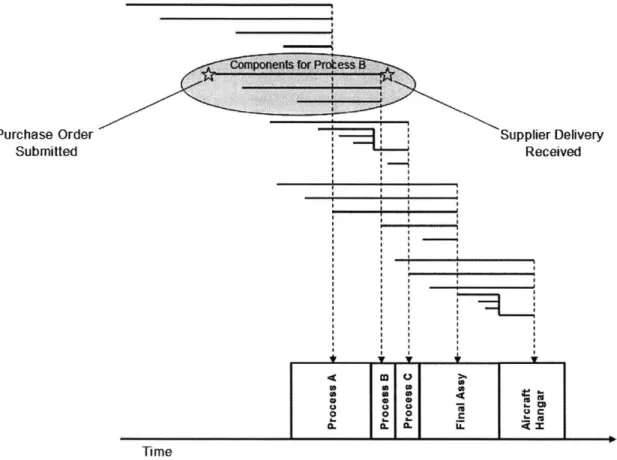
When the sales group ascertains how many helicopters the company aims to sell, the operations team enters the forecast and engineering Bill of Material into a Material Requirements Planning (MRP) system. With this computerized algorithm, an MRP controller synchronizes the arrival of components from suppliers so that the product can be assembled and available to the end customer on the expected need date.
In general, an MRP report informs supply chain managers what parts or materials to buy, how much to purchase, when to buy them, and when they need to arrive. The database usually invokes a buffer where more parts are ordered than necessary and delivered ahead of schedule to avoid any potential delays or shortages. Perhaps the most
significant parameter in MRP context is lead time, which is the time between the day a
component or assembly is ordered to the day it is delivered to the factory. Lead time
depends on multiple factors such as transportation, minimum order quantity, and design
complexity. The turnaround for an order is typically faster if a proficient vendor is
located near the facility and produces a commodity in low volume. An un-scaled MRP
tree diagram for a blade and its constituents is shown in Figure 11
Purchase Order Supplier Delivery
Submitted Received
Ti-me
Figure 11. Rough MRIP Illustration for Blade Fabrication
4.5 Enterprise Summary
Chapter 4 captures the logical flow of information from contract authorization to manufacturing. Yet, a closer look reveals that the enterprise is not entirely lean. In fact, even the smallest hiccup in upstream processes translates to greater stress on downstream activities. Configuring aircraft is a prime example, where a customer can modify the contract multiple times after an initial agreement is reached. Despite the flexibility,
re-negotiation hinders engineering if the design is altered, further delaying development progress. Purchasing efforts are compromised as well especially for components with long supplier lead times, which in turn postpones part availability. This case illustrates how uncertainty filters through the value chain, eventually impacting production. Due to the limited scope of the internship, the remainder of the thesis concentrates on lean issues in the factory.
In Chapter 5, we attempt to build on our understanding of the total enterprise by quantifying system performance specifically in the plant. Through the concept of value stream mapping, we intend to diagnose and classify wasteful activities in the existing plant that are tied to long manufacturing lead times. Using this tool, we also establish an ideal plan and set of operating guidelines for the future state factory.
Chapter 5: Value Stream Mapping at Sikorsky Aircraft
As mentioned in Section 3.3, a value stream is all the actions (both value-added and
non-value added) required to bring a product through the main flows essential to every
product: (1) the production flow from raw material into the arms of the customer, and (2)
the design flow from concept to launch (Rother and Shook, 1999). Chapter
5
deals with
door-to-door production flow inside the factory from customer demand back through raw
material.
Value Stream Mapping is a method to better understand the flow of material and
information as a product moves through the value stream. More specifically, it allows
one to follow the assembly path and track the steps that transform raw materials into
finished goods. The tool helps visualize flow across the entire plant, shows the linkage
between information and material, assists with identifying sources of waste, provides a
common language for discussing processes, represents a blueprint for lean
implementation, and describes qualitatively how a facility should operate to create flow
(Rother and Shook, 1999).
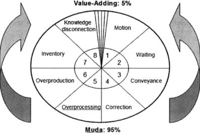
5.1 Classifying Waste
The elimination of non-value adding processes lies at the heart of any lean enterprise.
Figure 12 breaks down eight general types of waste and shows that nearly
95%
of daily
activities are governed by muda. True value, as stated by Taiichi Ohno, is literally the
size of a plum seed. A brief description of each waste is noted below (Dennis, 2002).
Value-Adding: 5% Knowtedige isconnection Motion Inventory 8 1 Wafting 7 2 6 3 Overproduction 5 4 Conveyance
VJe:
95%1. Motion - Poor ergonomics related to unnecessary walking, reaching, or twisting 2. Delay - Waiting for material to be delivered or a line stoppage to be cleared
3. Conveyance - Excess movement of parts from one process to another 4. Correction - Fixing defective product
5. Overprocessing - Doing more than what the customer desires 6. Overproduction - Making things that do not sell
7. Inventory - Surplus of raw materials, parts, and Work-in-Progress (WIP) 8. Knowledge Disconnect - Obstructs transfer of ideas and connection between a
company and the voice of the customer
5.2 Creating Value Stream Maps
A firm grasp on existing end-to-end rotor blade fabrication begins with an analysis of the current state value stream. The book Learning to See lists a few suggestions for
drawing a map (Rother and Shook, 1999):
" Always collect current-state data while walking the actual material and information flows yourself
* Begin with a quick walk along the entire door-to-door value stream * Begin with the shipping end and work upstream
* Bring your stopwatch and do not rely on standard times or information that you did not personally obtain
* Map the whole value stream yourself * Always draw by hand in pencil
Please refer to Appendix C and the textbook for additional details and instructions.
5.3 Inter-Plant Overview - K200 Main Blade
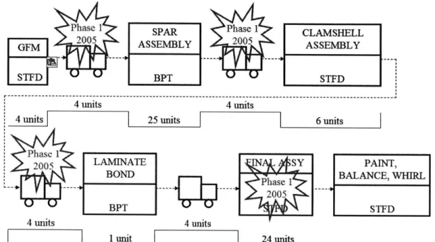
For a single plant scenario, the granularity of a value stream map should be on a door-to-door level. However, before pursuing this route, a broader plant-to-plant assessment is recommended due to ongoing Phase I equipment relocation. Figure 13 magnifies the
flow of main rotor blades between Stratford and the new facility. When the internship began, only 50% of production capability had been transferred, forcing Sikorsky to ship
blade, from incoming raw material to delivery to the aircraft hangar, was approximately
75
time units (masked for confidentiality). Of this amount, nearly 15% (12 units) was
consumed by inter-plant travel, which made transportation an enormous waste and
immediate priority for removal. In December 2005, the kit cutting tool was installed at
Site B, decreasing total lead time by 4 units. Relocation of final assembly is still in
progress, but the paint operation will remain in Stratford.
Phase I SPAR Phase
CLAMSHELL
GFM 2005 ASSEMBLY 2005 ASSEMBLY
STFD BPT STFD
4 units 4
units
4 units 25 units 6 units
Phase 1
2005 LAMINATEIN SY PAINT,
BOND BALANCE, WHIRL
- -Phase
1
200~
BPT I STFD
4 units 4
units
1
unit 24 unitsFigure 13. Inter-Plant Value Stream Map for K200 Main Blade
5.4 Current State - K200 Main Blade
The main blade current state map can be found in Appendix A. 1. Upon first glance, it is apparent how MRP is being used in the factory to estimate the demand for product. This push system encourages each process to operate independently, disconnected from the true needs of any downstream customer. One may counter that there are no tell-tale signs of MRP such as massive inventory between steps and long changeover times. However, it is arguable that K200 volumes are still too low to see the effects. The symptoms would be more visible when production ramps up four-fold within two years.
Based on the map, the process time, otherwise known as the value-added "hands on" time, equates to 20 units. But quite shockingly, the total production lead time shows that one blade takes 38 time units to move through the plant from start to finish, with the
exclusion of 12 additional units of plant-to-plant transportation noted in Section 5.2. The ratio of value-added to non-value added work is 0.40, which is better than the aerospace industry benchmark of 0.30. Even so, Womack and Jones firmly declare, "To hell with competitors; compete against perfection by identifying all activities that are muda and
eliminating them. This is an absolute rather than a relative standard that can provide the essential north star for any organization" (Womack and Jones, 1996).
5.5 Future State Vision - K200 Main Blade
Figure 14 displays the main blade future state map and represents an ideal, yet
realistic manufacturing system that can be attained. The goal for lean experts is to build a chain of production where the individual processes are linked to their customers either by continuous flow or pull, and each process gets as close as possible to producing only what its customers need when they need it (Rother and Harris, 2001). In defining future
state concepts, the rotor blade team answered the following crucial questions (Rother and Shook, 1999):
1. What is the takt time, based on the available working time of our downstream processes that are nearest the customer?
2. Will we build to a finished goods supermarket from which the customer pulls, or directly to shipping?
3. Where can we use continuous flow processing?
4. Where will we need to use supermarket pull systems in order to control production of upstream processes?
5. At what single point in the production chain (pacemaker process) will we schedule production?
6. How will we level the production mix at the pacemaker process?
7. What process improvements will be necessary for the value stream to flow as our future state design specifies?
These questions are explored in the order they are listed.
The takt time, known as the heart beat, matches the pace of sales with that of production. It can be numerically computed by dividing the available work time by the
WKLY
PROD CONTROL
QTRLY
SUPPLIER
ORDER
FORECAST
HG
SPARES
PLY
KITS
5 units
20
BLADES
PER MO.
PURCH
SHIP TICKETS
MAT'L
4EVERY
22 HRS
MA
---
-1 I
Spar
Clamshell
Laminate
Final
Paint Bal,
_iAss
y 1 MAXIMAX_BMAX
Asv
Whirl
~
l|ship
PACE
-FIFO-*
-FIFO-+
-
&Staging
2 units
2
units
2 units
2 units
10 units 23 units
units
ut
6 units
3 units
I'
foo
customer demand rate. With the main rotor blade, the equation can be expressed in the format below.
Takt Time = Available Time 225 brs / working day 45 h / blade Demand 10 blades /20 working days
This calculation is based on 3 shifts and 20 full work days in a calendar month. Since the plant fabricates ten blades per month, production control must release a ship ticket almost
every other day.
Whether to build blades to a supermarket or directly to shipping depends heavily on process reliability and the customer buying behavior. Because K200 manufacturing
expertise is still in the emerging stages, product yield is low but expected to improve over the next year. In addition, nearly 90% of scheduled and incoming orders are primarily
for aircraft sales. If a greater percentage of the business was driven by spares, then a make-to-order model would be advised. However, a finished goods supermarket is more suitable in light of the main blade characteristics.
Continuous flow refers to producing one piece at a time, with each item passed immediately from one process to the next without stagnation. For the main rotor blade, the spar fabrication and blade assembly steps are combined where possible to minimize accumulation of inventory. But, a few FIFO lanes are incorporated as a precaution to avoid merging all the lead times (and down times). Once process reliability increases, the FIFO lanes may be removed and replaced with single piece flow.
Aside from FIFO lanes, there are often spots in the value stream where batching is necessary (Rother and Shook, 1999). Some processes are far away and shipping one piece at a time is impossible. Others have too much lead time or are too unreliable to couple directly to other steps. The former case applies specifically to the blade shop as Sikorsky embraces the global market. With a growing number of parts being outsourced to external suppliers, the factory should create supermarkets for raw material and
purchased components. It is extremely important to install responsive pull signals (kanban) in these locations where continuous flow is interrupted.
The pacemaker process is essentially the scheduling point in the door-to-door value stream. In Figure 14, the final assembly area sets the pace for all upstream processes. Any delays or fluctuations in volume at this station will affect capacity requirements
throughout the factory. Also, leveling of the production mix at the pacemaker can be disregarded because the main blade line is solely dedicated to K200 output.
Numerous kaizen initiatives are necessary to achieve the future state and will be the subject of discussion in Chapter 6.
5.6 K200 Tail Blade
The current and future state maps for the tail rotor blade can be referenced in Appendix A.2 and A.3. Unlike the main blade, all production equipment for tail blade fabrication has been relocated to Site B with the exception of final paint, which shall reside in Stratford. Although tail blade manufacturing may appear to have more continuity due to less plant-to-plant travel, production lead time is estimated to be 49 units. However, tail blade process time is 10 units of actual work, roughly half that of a main blade. In constructing a future state vision, similar questions from Section 5.4 were raised to establish a sound operating system.
5.7 Chapter 5 Summary
In Chapter 5, we discussed the basis and criteria for value stream mapping and
applied the technique to better understand existing rotor blade processes in the plant. Utilizing VSM, we also crafted a vision for the ideal operating system through flow and kanban methodology. In Chapter 6, the author assesses the current factory and identifies potential improvements to achieve the future state. A set of tools are then developed to prioritize the opportunities and guide implementation for a specific initiative.