HAL Id: cea-02500831
https://hal-cea.archives-ouvertes.fr/cea-02500831
Submitted on 6 Mar 2020HAL is a multi-disciplinary open access archive for the deposit and dissemination of sci-entific research documents, whether they are pub-lished or not. The documents may come from teaching and research institutions in France or abroad, or from public or private research centers.
L’archive ouverte pluridisciplinaire HAL, est destinée au dépôt et à la diffusion de documents scientifiques de niveau recherche, publiés ou non, émanant des établissements d’enseignement et de recherche français ou étrangers, des laboratoires publics ou privés.
cameras
A. Charbal, J.-E. Dufour, F. Hild, M. Poncelet, S. Roux, L. Vincent
To cite this version:
A. Charbal, J.-E. Dufour, F. Hild, M. Poncelet, S. Roux, et al.. Stereo-DIC using high magnification infrared and visible cameras. 22ème Congrès Français de Mécanique, Aug 2015, Lyon, France. �cea-02500831�
Stereo-DIC using
high magnification infrared and visible cameras
A. CHARBAL
a,b, J.E. DUFOUR
b, F. HILD
b, M. PONCELET
b, S. ROUX
b,
L. VINCENT
a(a) LMT, ENS Cachan / CNRS / Univ. Paris Saclay, 61 avenue du Président Wilson
F-94235 Cachan cedex, France
{charbal ,dufour, hild, poncelet, stephane.roux}@lmt.ens-cachan.fr
(b) CEA, DEN, DMN, SRMA, F-91191 Gif-sur-Yvette cedex, France
[email protected]
Résumé :
Des mesures de champs cinématiques 3D sont réalisées en utilisant une combinaison originale bimodale de deux caméras (l’une infra-rouge(IR) avec un objectif G1 et l’autre visible). L’appariement des images acquises par les deux imageurs est mené par une méthode globale de Stéréo Corrélation d’Images Numériques (SCIN) [1]. Le système de stéréovision est étalonné, d’une part en corrigeant les distorsions provoquées par les optiques [2] et d’autre part en déterminant les paramètres du modèle projectif. A l’aide d’une représentation CAO (NURBS) de la surface de l’objet observé ces paramètres sont déterminés en utilisant une approche intégrée de SCIN. Cette technique permet la mesure de la cinématique de la pièce étudiée. Le cas de translations de corps rigides est étudié expérimentalement pour illustrer la méthode et la valider..
Abstract:
Measurements of kinematic fields are performed with an original combination of two different imaging modalities, (i.e. one IR and one visible camera). Stereo Digital Image Correlation (SDIC) procedures are performed with a global approach [1]. The stereovision system is first calibrated by performing lens distortion corrections [2]. Then the projection model parameters are determined thanks to the CAD (NURBS) representation of the 3D sample surface using an integrated approach. This CAD-based SDIC, offers the possibility to determine the specimen deformation. The simple case of3D rigid translational motions is experimentally tested and validated.
1
Introduction
An experimental setup [4] is developed in order to assess the thermomechanical cyclic behavior and fatigue resistance of austenitic stainless steels during thermal fatigue loadings that may occur in nuclear power plants [5–7]. IR and visible cameras are used to measure the kinematic and thermal fields during cyclic laser shocks, respectively [8]. The simulations of the fatigue test [9] predict large out-of-plane strains during loading. In order to measure out-of-plane motions, it is necessary to perform stereo digital image correlation (SDIC) [10–12]. The combination of both imaging systems to conduct SDIC for translational motion at room temperature is described in ref. [3]. The IR camera with a 50-mm lens and 12-mm extension ring leads to a physical pixel size of 60 µm, which is limiting when performing 3D surface DIC on thermal fatigue experiments. The in-plane and out-of-plane motions are as small as 5-10 µm [9]. It is proposed to perform a feasibility analysis with translational rigid body motions by resorting to a high magnification lens, also known as G1 lens, for the IR camera that provides pixel sizes of the order of 15µm. The experimental configuration requires SDIC to be performed with an inclined visible camera and an IR camera normal to the object. This choice is due to the depth of field of the IR camera, which is at most equal to 100 µm. Following the global approach developed in Ref. [3] a SDIC framework using a NURBS [13] description of the sample surfaces is used. Lens distortion corrections [14, 15] are performed for both imaging systems using an Integrated Digital Image Correlation (I-DIC) procedure [2]. An integrated approach to measure only 3D translational motions [1] is also implemented.
The paper is divided into 3 parts. The experimental setting and characterized sample are first presented. Then the formalism of CAD-based SDIC is briefly introduced. Finally the first results are discussed.
2
Experimental settings
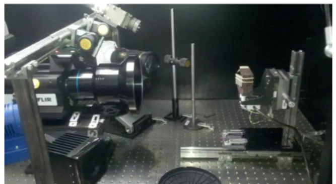
In order to have a better spatial resolution, a G1 lens is used for the IR camera (FLIR x6540sc, 640x512 pixels, pitch=15m). The observed sample imposes the camera to be positioned normal to the sample surface (see Figure 1) due to its low depth of field. A high speed visible camera (Miro, M320, 1920x1200 pixels, pitch=10m) is used with also a x1 magnification factor lens (Tamron 180mm f/3.5 Macro lens) and yet a larger depth of field that allows us to tilt this camera with respect to the normal of the plate sample used in thermal fatigue experiments.
Figure 1: Stereojig with the IR (with G1 lens) and visible cameras where the motions are applied manually along the 3 axes
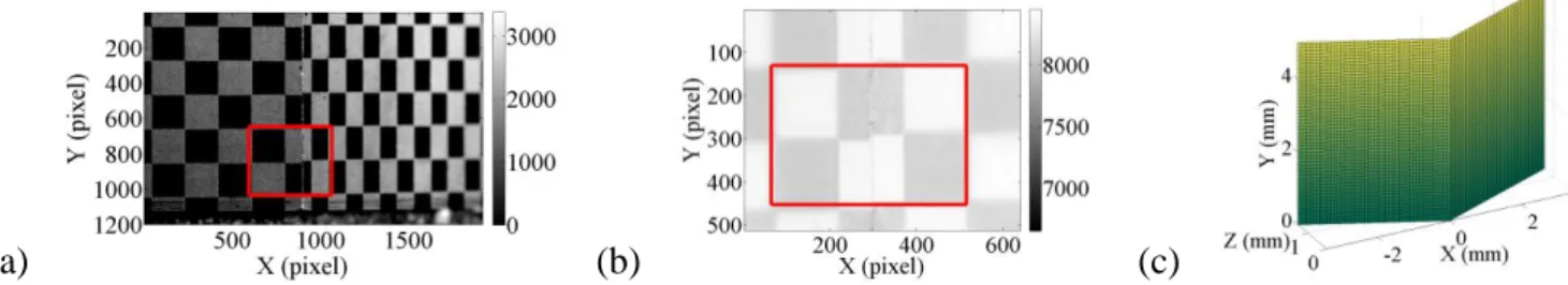
In this paper, an open book target made of aluminum alloy is used for the calibration of the experiment (see also in [16] a prior calibration of a high speed experiment with the same target). Its
size is 30 × 30 × 1 mm3 and the opening angle is 132°. The pattern is made of regular white and
black squares of 2.5 × 2.5 mm2 area. The pictures shot by the visible and IR cameras, and the numerical model of the target are shown in Figure 2. Due to lighting, the sample temperature rises up to 32 C. The temperature of the sample is assumed to remain constant and uniform during the experiment.
Figure 2: 3D Calibration target captured by (a) the visible and (b) the IR cameras and its mathematical model (c) with the dimensions of the region of interest (shown as a red rectangle in (a) and (b))
It is worth mentioning that the gray level distributions in the pictures shot with the IR and visible cameras are different. This induces that the squares that correspond to the black color in the visible pictures correspond to white squares in the IR images. The dynamic ranges are also different from an imaging system to another. Hence a histogram readjustment is performed on the IR frames in order to have similar color correspondence and dynamic range from both modalities.
3
Calibration procedures
Before performing SDIC analyses, several calibration phases are needed. The first one corresponds to distortion corrections. As both imaging systems do not have the same lenses, the induced distortion on the pictured images are completely different. As the images are projected onto a CAD model that is supposed to be perfect, such effects might yield errors on the determination of transformation matrices and motion measurements. The technique to account for such biases uses I-DIC [2], which allows for the intrinsic parameters such as radial, decentering and prismatic coefficients [14, 15] to be determined.
Once the images are corrected of their respective distortions, the transformation matrices are estimated allowing the 3D NURBS-based CAD model [17] to be projected [1].
3.1 Distortion corrections
The visible camera is calibrated using a 2D target with a printed pattern [2]. Since the pattern is known, it is possible to generate a numerical, i.e. distortion-free, reference image. By using the pair of images (picture of the target and its corresponding numerical reference) it is possible to estimate the lens distortion. The numerical reference and the imaged calibration target are shown in Figure 3.
(a) (b)
Figure 3: Calibration target: (a) reference, and (b) distorted images for the visible camera (the image definition is 1080×1920 pixels digitized with 4096 gray levels)
The measured distortion fields are displayed in Figure 4. They are nearly equal to zero in the center of the image and can reach 4 pixels (i.e. 40 µm) near the image borders.
(a) (b)
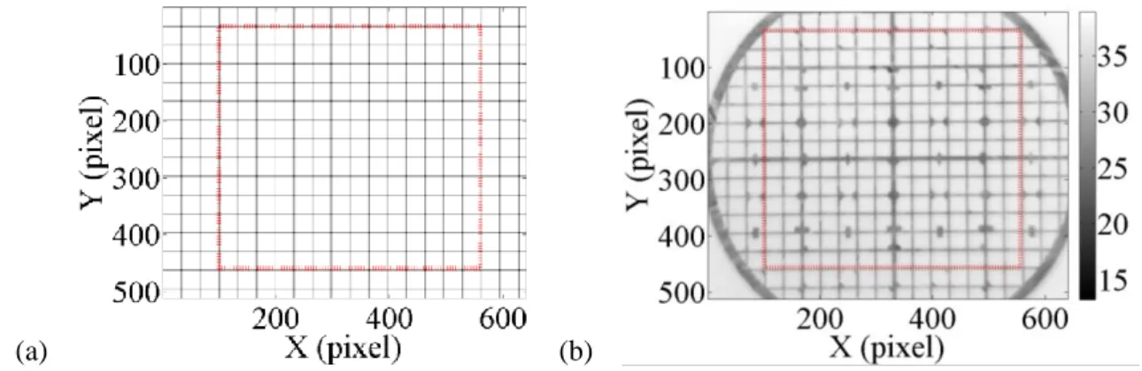
Figure 4: Distortion fields (a) Ux and (b) Uy (color bar expressed in pixels) for the visible camera Similarly, the IR camera with a G1-lens is calibrated. As the previous 2D target does not provide enough contrast at room temperature, another target is used. A grid made of copper is glued onto a black painted surface. The difference of emissivities (i.e. low for copper and high for the black paint) provides the needed contrast. According to the manufacturer the mesh length is 480 µm so that a simple grid is generated. The latter is used as a reference in the red region of interest (ROI) of Figure 5.
(a) (b)
The measured distortion fields are illustrated in Figure 6. As observed with the visible camera, the distortion fields are approaching zero in the image centre and can reach 1.5 pixel (or 22.5 µm) near the image borders.
( a)
b)
Figure 6: Distortions fields (a) Ux and (b) Uy (color bar expressed in pixel) for the IR camera (with G1 lens)
Once the pictures are corrected from the estimated lens distortions, it is possible to perform the next step, which consists of determining the transformation matrices.
3.2 Transformation matrices
This calibration step consists of determining the transformation matrices accounting for the 3D coordinates of the numerical (i.e. CAD) model projected onto the picture planes. The global approach proposed in Ref. [1] considers the numerical 3D model as the master, and the two cameras have exactly the same (slave) status. An I-DIC algorithm allows for the determination of the transformation matrices by using a pseudo-kinematic basis. By working in the parametric space of the surfaces, it enables for images of different definition and nature to be registered. The homogeneous coordinates in each camera are related to the 3D positions by
{s lxl slyl sl } = [𝐌𝐥][𝐗] and {s rxr sryr sr } = [𝐌𝐫][𝐗] (1)
where [𝐌𝐥,𝐫] denotes transformation matrices for the left and right cameras, [𝐗] the homogeneous coordinates, xl,r and yl,r the pixel coordinates in each camera, and sl,r the scale factors for the left and
right cameras. I-DIC consists of minimizing the functional τ
τ = ∫[f(𝐱𝐥(u, v, [𝐌𝐥]) − g(𝐱𝐫(u, v, [𝐌𝐫])]𝟐dudv 𝐑𝐎𝐈
(2)
with respect to the unknown matrix components, where u and v denote the parametric coordinates of the surface model. Its linearization with respect to the corrections dMijl,r of the sought quantity yields
τlin = ∫[f(𝐱𝐥) − g(𝐱𝐫) + (𝛁f ∙ 𝛅𝐱𝐥)(𝐱𝐥) − (𝛁g ∙ 𝛅𝐱𝐫)(𝐱𝐫)]𝟐dudv 𝐑𝐎𝐈
This leads to an iterative scheme updating the positions in the IR and visible cameras by computing the sensitivity fields
𝛅𝐱𝐥,𝐫 = ∂𝐱𝐥,𝐫
∂Mijl,rdMij
l,r
(4)
At convergence, the gray level residual shows that the black and white squares are matching (Figure 7). The high level, i.e. 25 % of the dynamic range is due to the fact that both imaging systems do not have the same gray level distribution. The only gray level correction performed at this stage is a histogram adjustment so that the images have the same minimum and maximum gray levels.
Figure 7: Gray level residual obtained after the determination of the transformation matrices Once the transformation matrices are determined, it is possible to perform SDIC analyses to measure 3D displacements by registering the reference and deformed images shot by the IR and visible cameras.
4
3D surface motions
4.1 Integrated approach
An extension of the method proposed in Ref. [1] is used to measure only translational motions. This allows the number of degrees of freedom to be reduced. SDIC is performed by registering both image pairs by minimizing the following functional
𝛕 = ∫[f(𝐱𝐥(u, v, 𝑷 𝒊𝒋) − g(𝐱𝐥(u, v, 𝑷𝒊𝒋+ 𝒅𝑷𝒊𝒋)] 𝟐 dudv 𝐑𝐎𝐈 + ∫[f(𝐱𝐫(u, v, 𝑷 𝒊𝒋) − g(𝐱𝐫(u, v, 𝑷𝒊𝒋+ 𝒅𝑷𝒊𝒋)] 𝟐 dudv 𝐑𝐎𝐈 (5)
where 𝑷𝒊𝒋 are the control points of the NURBS surface, which consist in this case of a 3 × 15 coordinates defining the 15 control points. The displacement fields are then obtained by estimating the motions 𝒅𝑷𝒊𝒋 of the control points in the deformed images g. A Newton-Raphson algorithm is implemented to minimize the previous functional. The linear equations to solve read
[𝐂]{𝐝𝐩} = {𝐛} (6)
[𝐂] = ∫ (𝝏𝒙𝒓 𝝏𝑷𝒊𝒋 ∙ 𝜵𝒇𝒓𝜵𝒇𝒓∙ 𝝏𝒙𝒓 𝝏𝑷𝒊𝒋 + 𝝏𝒙𝒍 𝝏𝑷𝒊𝒋 ∙ 𝜵𝒇𝒍𝜵𝒇𝒍∙ 𝝏𝒙𝒍 𝝏𝑷𝒊𝒋 ) 𝑹𝑶𝑰 𝒅𝒖𝒅𝒗 = [𝑫𝒓]𝑻[𝑫𝒓] + [𝑫𝒍]𝑻[𝑫𝒍] (7)
and the unknowns are incrementally determined as
{𝐝𝒑} = {𝒅𝑷𝒊𝒋} (8)
and the DIC vector
{𝐛} = [𝑫𝒓]𝑻(𝑓𝑟− 𝑔𝑟) + [𝑫𝒍]𝑻(𝑓𝑙− 𝑔𝑙) (9)
where the superscript r denotes the current iteration.
Albeit this strategy allows for the measurement of a full kinematic field discretized in a consistent framework with the CAD model, it is proposed to resort to I-DIC to measure only rigid body translations (i.e. a subset of the range of possible displacement fields). The reduced DIC matrix becomes [𝐂𝑹𝑩𝑻] = ∫ ( 𝝏𝒙𝒓 𝝏𝒑𝑹𝑩𝑻 𝝏𝒑𝑹𝑩𝑻 𝝏𝑷𝒊𝒋 ∙ 𝛁𝒇𝒓𝜵𝒇𝒓∙ 𝝏𝒑𝑹𝑩𝑻 𝝏𝑷𝒊𝒋 𝝏𝒙𝒓 𝝏𝒑𝑹𝑩𝑻+ 𝝏𝒙𝒍 𝝏𝒑𝑹𝑩𝑻 𝝏𝒑𝑹𝑩𝑻 𝝏𝑷𝒊𝒋 ∙ 𝛁𝒇𝒍𝜵𝒇𝒍 𝑹𝑶𝑰 ∙ 𝝏𝒑𝑹𝑩𝑻 𝝏𝑷𝒊𝒋 𝝏𝒙𝒍 𝝏𝒑𝑹𝑩𝑻) 𝒅𝒖𝒅𝒗 (9) which is rewritten as [𝐂𝑹𝑩𝑻] = [𝚪𝑻][𝐂][𝚪] (10)
where [𝚪] allows rigid body translation to be measured. This new expression reduces the kinematic unknowns to three parameters to be determined directly with no additional reprojection. The residual vector then reads
{𝐛𝑹𝑩𝑻} = [𝚪𝑻]{𝐛} (11)
Since the measurements are performed at room temperature, the gray and digital level conservation is satisfied up to acquisition noise.
4.2 Measurements of translation motions
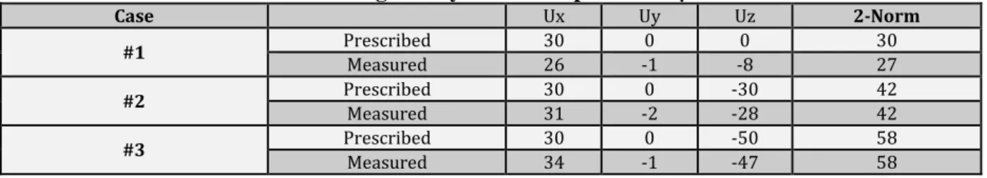
The translational motions are performed by using a manual 3-axis stage. The prescribed and measured rigid body motions are listed in Table 1.
Table 1: Prescribed and measured rigid body motions expressed in µm
Case Ux Uy Uz 2-Norm #1 Prescribed 30 0 0 30 Measured 26 -1 -8 27 #2 Prescribed 30 0 -30 42 Measured 31 -2 -28 42 #3 Prescribed Measured 30 34 -1 0 -50 -47 58 58
According to the displacement fields shown in Figure 8 and the values reported in Table 1, the displacements are well captured. The difference in terms of displacement component is mostly due to misalignments between the target frame and that of the 3-axis stage. For instance, case #1 where the translational motion is performed only along the x-direction, a motion of -8 µm is measured along the z-direction whereas it should equal 0 µm. When expressed in terms of the 2-norm, the errors are lowered and a rather good match is observed. Some errors can be introduced by other effect such as defocusing, which induces blurring of the images. As an integrated approach is used, the results are less sensitive to such effects as long as the amount of blurring is not too large.
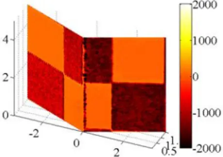
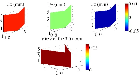
Figure 8: Measured rigid body motions (expressed in mm) corresponding to case #3
Globally the SDIC residuals normalized by the dynamic range of the reference pictures are smaller for the visible camera (0.3 to 1.5 %, see Figure 9(a)) when compared with the IR camera (0.8 to 8.31 %, see figure 9 (b)) when 3D displacements are measured.
(a) (b)
Figure 9:Gray and digital level residuals for the visible (a) and IR (b) cameras for displacement measurements
Remembering that the two imaging systems do not provide pictures with the same histograms the residuals are deemed satisfactory. Adjusting the dynamic range of both images, as performed herein, is not completely satisfactory and more advanced procedures should be implemented. This is important when the temperature varies, since the reference and deformed IR images will experience gray level variations, which will be interpreted in terms of temperature fields [18].
5
Conclusion
A new configuration combining IR and visible cameras has been tested for SDIC purposes. The new configuration has the IR camera normal to the observed sample surface. Using a high magnification increases the spatial resolution but reduces the depth of field. The new configuration is
calibrated by first estimating the lens distortions [2] for both imaging systems. Near the image borders the distortions are estimated to be of the order of 40 µm for the visible camera and 22 µm for the IR camera. Once the images are corrected of the estimated distortion a CAD-based SDIC using a NURBS model of the calibration target is considered to determine the transformation matrices. Working in the parametric space of the 3D surface allows the two images of different definitions and resolutions to be registered. A simple histogram readjustment on the IR image is performed to make DIC analyses possible. In a final stage, integrated SDIC is implemented to measure translational rigid body motions. The results are satisfactory as measured amplitudes are close to the prescribed ones to within a few micrometres.
References
[1] B. Beaubier, J.-E. Dufour, F. Hild, S. Roux, S. Lavernhe, and K. Lavernhe-Taillard, “CAD-based calibration and shape measurement with stereoDIC,” Exp. Mech., vol. 54, no. 3, pp. 329– 341, Mar. 2014.
[2] J.-E. Dufour, F. Hild, and S. Roux, “Integrated digital image correlation for the evaluation and correction of optical distortions,” Opt. Lasers Eng., vol. 56, no. 0, pp. 121 – 133, 2014.
[3] A. Charbal, J.-E. Dufour, F. Hild, M. Poncelet, L. Vincent, and S. Roux, “Hybrid Stereo-DIC using iNfrared and visible cameras,” presented at the Photomechanics international conference. DELFT. NDL, 2015.
[4] L. Vincent, M. Poncelet, S. Roux, F. Hild, and D. Farcage, “Experimental Facility for High Cycle Thermal Fatigue Tests Using Laser Shocks,” Fatigue Des. 2013 Int. Conf. Proc., vol. 66, no. 0, pp. 669–675, 2013.
[5] A. Amiable, S. Chapuliot, S. Contentinescu, and A. Fissolo, “A computational lifetime prediction for a thermal shock experiment, Part I: Thermomechanical modeling and lifetime prediction,” Fatigue Fract. Eng. Mater. Struct., vol. 29, pp. 209–217, 2006.
[6] A. Fissolo, S. Amiable, O. Ancelet, F. Mermaz, J. M. Stelmaszyk, A. Constantinescu, C. Robertson, L. Vincent, V. Maillot, and F. Bouchet, “Crack initiation under thermal fatigue: An overview of CEA experience. Part I: Thermal fatigue appears to be more damaging than uniaxial isothermal fatigue,” Int. J. Fatigue, vol. 31, no. 3, pp. 587–600, Mar. 2009.
[7] A. Fissolo, C. Gourdin, O. Ancelet, S. Amiable, A. Demassieux, S. Chapuliot, N. Haddar, F. Mermaz, J. M. Stelmaszyk, A. Constantinescu, L. Vincent, and V. Maillot, “Crack initiation under thermal fatigue: An overview of CEA experience: Part II (of II): Application of various criteria to biaxial thermal fatigue tests and a first proposal to improve the estimation of the thermal fatigue damage,” Int. J. Fatigue, vol. 31, no. 7, pp. 1196–1210, Jul. 2009.
[8] C. Esnoul, L. Vincent, M. Poncelet, F. Hild, and S. Roux, “On the use of thermal and kinematic fields to identify strain amplitudes in cyclic laser pulses on AISI 304L strainless steel,” presented at the Photomechanics, Montpellier, 2013.
[9] A. Charbal, L. Vincent, F. Hild, M. Poncelet, S. Roux, and D. Farcage, “Characterization of temperature and strain fields during cyclic laser shocks,” presented at the 12th International Conference on Quantitative Infrared Thermography, QIRT, Bordeaux, France, 2014.
[10] M. A. Sutton, J. . Orteu, and H. W. Schreier, Image Correlation for Shape,Motion and
Deformation Measurements. Springer, 2009.
[11] J.-J. Orteu, “3-D computer vision in experimental mechanics,” Opt. Meas., vol. 47, no. 3–4, pp. 282–291, Mar. 2009.
[12] F. Hild and S. Roux, “Digital Image Correlation,” in Optical Methods for Solid Mechanics : A
Full-Field Approach, WILEY-CH, 2012.
[13] J.-E. Dufour, F. Hild, S. Roux, and B. Beaubier, “Displacements measurements using CAD-based stereo-correlation with meshes,” presented at the ICEM16 -16th International Conference on Experimental Mechanics, 2014.
[14] D. C. Brown, “Decentering distortion of lenses,” Photogrammetric Engineering, pp. 444–462, 1966.
[15] D. C. Brown, “Close-range camera calibration,” Photogrammetric Engineering, pp. 855–866, 1971.
[16] G. Besnard, J.-M. Lagrange, F. Hild, S. Roux, and C. Voltz, “Characterization of Necking Phenomena in High-Speed Experiments by Using a Single Camera,” EURASIP J. Image Video
Process., vol. 2010, no. 1, p. 215956, 2010.
[17] L. Piegl and W. Tiller, The NURBS Book, 2nd ed. Springer, 1997.
[18] A. Maynadier, M. Poncelet, K. Lavernhe-Taillard, and S. Roux, “One-shot thermal and kinematic field measurements: Infra-Red Image Correlation,” in Application of Imaging
Techniques to Mechanics of Materials and Structures, Volume 4, T. Proulx, Ed. Springer New