HAL Id: tel-02341319
https://tel.archives-ouvertes.fr/tel-02341319
Submitted on 31 Oct 2019HAL is a multi-disciplinary open access archive for the deposit and dissemination of sci-entific research documents, whether they are pub-lished or not. The documents may come from teaching and research institutions in France or abroad, or from public or private research centers.
L’archive ouverte pluridisciplinaire HAL, est destinée au dépôt et à la diffusion de documents scientifiques de niveau recherche, publiés ou non, émanant des établissements d’enseignement et de recherche français ou étrangers, des laboratoires publics ou privés.
Ahmed Abudabbousa
To cite this version:
Ahmed Abudabbousa. OFDM based Time Difference Of Arrival Estimation. Electromagnetism. Sorbonne Université, 2018. English. �NNT : 2018SORUS112�. �tel-02341319�
Sorbonne Université
Ecole doctorale : EDITE 103
Laboratoire d’Électronique et Électromagnétisme
OFDM based Time Difference Of Arrival Estimation
Par Ahmed Abudabbousa
Thèse de doctorat d’Électronique
Dirigée par M. Aziz Benlarbi-Delaï
Présentée et soutenue publiquement le 17/04/2018 Devant un jury composé de :
Mme Boukour Fouzia, Directrice de recherche rapporteur
M. Loyez Christophe, Directeur de Recherche rapporteur
M. De Donker Philippe, Professeur Examinateur
M. Kokabi Hamid, Professeur Examinateur
M. Benlarbi-Delaï Aziz, Professeur Directeur de thèse
This research is dedicated:
To my parents: my dear father “Issa” who spent his life to grow mine, and my
sweethearted mother “Boshra” who is the spring that never stops giving.
To my wife “Areej”, there are no words that could describe how I am grateful
for her support and encouragement throughout the years.
To “Nima”, who has always been by my side and gave me assistance.
To my daughter “Boshra” for her patience and understanding.
My deepest gratitude to my brothers: “Tamer”, “Ghassan”, “Housam”, and my
sisters “Inas” “Faten” “Nesrean”.
Finally, to all my family members who have been a constant source of
motivation, inspiration, and support.
Acknowledgments
First and foremost, I would like to express my deep appreciation to my
director Prof. Aziz Benlarbi-Delaï for providing advice, support and excellent
guidance. The warm discussions and regular meetings I had with him during this
research. His spirit of youth contributed greatly to the successful completion of
this research.
I also thankful to the members of jury particularly the reviewers Mme
Boukour Fauzia, M. Loyez Christophe who their recommendations were very
useful. In continue, thanks to M. De Donker Philippe, M. Kokabi Hamid and M.
Sarrazin Julien.
I owe a deep debt of gratitude to the Islamic university of Gaza, Sorbonne
University, the Phoenix project for giving me an opportunity to complete this
work by providing me all the efforts and facilities.
Finally, I would like to take this opportunity to thank warmly all my
beloved friends, who have been very supportive during my thesis, especially my
best friend Amine Rabehi.
Abstract
Wireless technologies make possible the emergence of smart environment where different things are interconnected to each other to give people more services and flexibility. Due to that, a huge number of connected objects, expected to reach tens of billions by 2030, will be attached to the network and will need a huge amount of energy. This energy, usually expressed in time and frequency domains, needs to be reduced and may benefit from the optimal exploitation of the third domain: the spatial resource.
We focus on this last domain, since finding the position of the connected objects can help to perform multi-hop communication, or to achieve energy and data focalization, leading to energy efficient communication. Finding the position means generally performing triangulation, through pseudo-distances, which in turn means time delay management. So far, among several time estimation techniques, Time Difference Of Arrival (TDOA) seems to be a good candidate to combine accuracy and ease of use, especially for the short-range indoor application.
In order to help the emergence of a low added complexity indoor location system, our contribution consists of a TDOA based solution that exploits the OFDM based popular communication signals. In this work, we perform, using a Multiple Inputs Simple Output, channel characterization and modeling for TDOA estimation. By handling these channel frequency responses in different ways, we minimize different cost functions expressed as the difference between measured channel response and a predefined direct model. For validation, the simulation based on different topologies exhibit results pointing out the property of super-resolution of such approach. The performance of the proposed TDOA estimation is compared to the Cramer Rao Lower Bound. The effects of the multipath are taken into account and some proposed solutions are discussed and simulated. Moreover, the experimental part of this work validates both the direct and inverse models in different channel configurations.
Contents
Acknowledgments ... iv
Abstract vi
Contents viii
General Introduction ... 1
Chapter 1: Context and State of the art of Indoor Positioning ... 5 Introduction ... 5
1.1
Indoor positioning: a critical need ... 5
1.2
Context ... 5
1.2.1
General definitions ... 6
1.2.2
Indoor Positioning Systems ... 8
1.3
Infrared (IR) Positioning Systems ... 8
1.3.1
Ultra-sound Positioning Systems ... 8
1.3.2
Radio Frequency (RF) Positioning Systems ... 9
1.3.3
Alternative systems ... 11
1.3.4
Measuring Principles ... 14
1.4
RF Metrics for Wireless Localization ... 14
1.4.1 Scene Analysis ... 21 1.4.2 Proximity ... 21 1.4.3 Conclusion ... 21 1.4.4 Objectives ... 22 1.5 Conclusion ... 23 1.6 Bibliography ... 24
Chapter 2: Multi carrier communication signals ... 29 Introduction ... 29
2.1
General principle of MC based TDOA estimation ... 29
2.2
Multi carrier based positioning systems and OFDM solutions ... 30
2.3 Blind solution ... 30 2.3.1 Training solution ... 30 2.3.2 Alternative solution ... 31 2.3.3
OFDM based positioning ... 31
Conclusion ... 31
2.3.5
Data modulation ... 32
2.4
QPSK Based Communication System ... 32
2.4.1
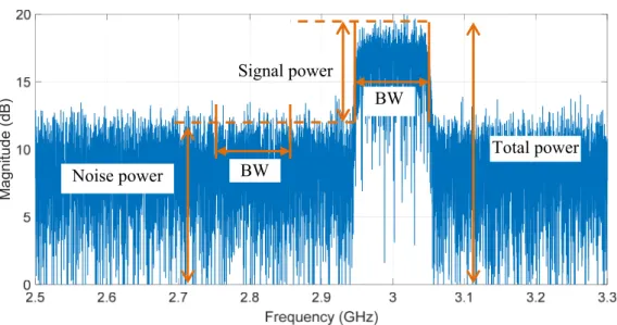
SNR calculation ... 33
2.4.2
Simulation results ... 35
2.4.3
OFDM communication system ... 38
2.5
Transmitter/Receiver module ... 38
2.5.1
Guard Interval ... 39
2.5.2
Guard Band and roll of factor ... 43
2.5.3 MATLAB implementation ... 44 2.6 Transmission part ... 44 2.6.1 Reception part ... 45 2.6.2 Channel Estimation ... 46 2.7 Pilot block ... 47 2.7.1 Mathematical derivation ... 48 2.7.2
Channel estimation testing ... 50
2.7.3
Conclusion ... 51
2.8
Bibliography ... 52
Chapter 3: OFDM based TDOA estimation ... 55 Introduction ... 55
3.1
Algorithms for TDOA-based positioning ... 55
3.2
Definition of the direct model ... 56
3.3
Frequency limitation ... 57
3.3.1
Signal model ... 58
3.3.2
Energy based approach ... 59
3.3.3
Channel based approach ... 59
3.3.4
Inverse problem: TDOA extraction ... 64
3.4
Large TDOA ... 64
3.4.1
Small TDOA ... 65
3.4.2
Very small TDOA ... 72
3.4.3
Cramer Rao Bound Limit ... 75
3.4.4
Communication parameters effect ... 76
3.5
Estimation of the coefficients , ... 76
3.5.1
Number of pilots ... 77
3.5.2
Communication environment effect ... 78
Multipath modeling ... 78
3.6.1 Emulating Multipath ... 79
3.6.2 Multipath effect reduction ... 80
3.6.3 Conclusion ... 82
3.7 Bibliography ... 83
Chapter 4: Experimental setup and results ... 85
Presentation of the environment ... 85
4.1 The controlled electromagnetic room ... 85
4.1.1 Radiating devices ... 87
4.1.2 Amplifier ... 87
4.1.1 Arbitrary waveform generator ... 88
4.1.2 Digital storage oscilloscope ... 88
4.1.3 Conclusion ... 89
4.1.4 SISO communication system setup ... 89
4.2 The transmitter ... 89
4.2.1 The receiver ... 91
4.2.2 Signal acquisition and I-Q constellation ... 92
4.2.3 OFDM communication performances ... 95
4.2.4 Channel estimation ... 96
4.2.5 Direct and Inverse models validation ... 98
4.3 MISO configuration ... 98
4.3.1 Baseline calculation ... 99
4.3.2 Calibration MISO system ... 100
4.3.1 MISO configuration for TDOA estimation ... 101
4.3.2 Direct model validation ... 102
4.3.3 Inverse model validation ... 104
4.3.4 Multipath effects ... 105
4.3.5 Conclusion ... 107
4.4 Conclusions and perspectives ... 109
Abbreviations ... 113
List of Figures ... 115
General Introduction
The vision of Internet of Things (IoT), making everyday objects readable, recognizable, locatable, addressable, and controllable, will plunge people in smart environments rich of new experiences and opportunities. Actually, due to the demand of increased mobility and flexibility in our daily life, we assist today to a widespread deployment of wireless local and personal area networks, which beside the upcoming billions of connected objects, appeal new radio solutions that 5G promises to offer.
In order to address these huge needs, the future development of 5G considers a greater number of base stations than today, and it is no doubt that this will involve massive additional power consumption. So it becomes clear that efficient energy communications are more than ever required to answer economic issues and sustainability.
It is well known that in current wireless local and personal area networks, the spectrum congestion, the low energy efficiency communications and the insufficient exploitation of the spatial resources are among the factors that may slow down the development of IoT or IoE (Internet of Everything). To overcome these forthcoming restrictions, wireless location technology, as the mechanism for discovering relationship between connected objects, appears as one of the key solutions. This is because dedicated localization techniques in wireless communication can help in developing more extensively the exploitation of spatial resources and allow driving optimized routing algorithms for low energy multi hops communication and spectrum decongestion for Green ICT (Information and Communication Technology) by means of cognitive radio. Beside this, location already starts playing a major role to promote another emerging vision: a spatio-temporal Internet of Places (IoP), which would be able to structure and organize the spatial content of Internet.
To be ubiquitous, and hence compliant with the so-called Intelligent Ambience, location systems need to be embedded in various connected objects, even the smallest ones, and to be infrastructure free solution. This requires a specific attention regarding the size of proposed solutions, and regarding the added complexity to already existing infrastructures.
However, to truly achieve ubiquitous positioning, proposed solutions should solve problems and challenges related to the Non Line-of-sight (NLOS) propagation, signal scattering and multipath effects, interferences, vulnerability to environment changes, computational complexity and fine resolution. Facing these challenges, the localization, seen as a multidimensional problem, appears more complicated to perform and therefore many scientific areas such as specific channel modeling, algorithmic, statistics, RF circuit, and system design, hard/soft approach should be simultaneously considered in order to define a veritable science of localization.
To address these needs, and in order to help the emergence of a low added complexity indoor accurate location, our contribution consists with a Time Difference Of Arrival (TDOA) based solution that exploits already existing popular communication signals involved in 4G, and compliant with upcoming new radio solutions proposed for 5G.
So it appears relevant to perform a specific channel characterization and modeling dedicated to TDOA estimation, and later to location. Actually as the channel acts as an important transfer function whose knowledge is required, the time delay estimation needs a deep understanding of the channel behavior, to enhance the performance of the numerous approaches we dealt with.
This thesis report is structured as follows: chapter 1 starts by introducing the critical needs of the indoor positioning, and give o brief overview of existing technologies. The main wireless RF metrics for location are exposed and finally, stating the objectives of this research ends this chapter.
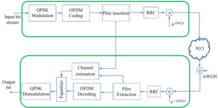
Second Chapter starts with the literature review of using the multicarrier signals, in indoor position especially, for Time Difference of Arrival estimation. The implementation of communication systems using multicarrier signal will be illustrated mathematically which include OFDM transmitter and receiver based QPSK modulation, SNR calculation, cyclic prefix, and channel estimation.
In the third chapter, a new TDOA estimation method based on the channel estimation is presented. After presenting the state of the art of TDOA estimation, we develop all the mathematical derivations leading to the definition of the direct problem. With that, the simulation results, based on different topologies described by different block diagrams, are
presented, and the performance of the proposed TDOA estimation, stating the inverse problem, is compared to Cramer Rao Lower Band. At the end, the effects of the multipath are demonstrated and some proposed solution are discussed and simulated.
Finally, the fourth chapter, as experimental part of this work, validates both the direct and inverse models in different channel configurations. Conclusion and perspectives end this work.
Chapter 1: Context and State of the art of Indoor
Positioning
Introduction
1.1
The indoor positioning (IP) seems to be a key piece to give Personal Networks a better functionality, meeting the requirements in terms of agility, configurability, connectivity, and energy efficient communication. The indoor positioning is also serving many applications in various domains (health, entertainment, military …) making it really relevant and almost unavoidable.
The present chapter gives a brief overview describing these needs and the technical means to achieve them. After exposing the main metrics and the state of the art, we define the objectives we target in this work and justify the main choices we made.
Indoor positioning: a critical need
1.2
Context
1.2.1
Personal Networks have been designed to meet the demands of users to interconnect their various personal devices at different places into a single network as shown in Figure 1-1.
Figure 1-1: Personal Networks (PNs) [1]
This architecture will emerge new concepts and features for wireless data transmission and transponder systems. Some of the numerous possible application areas are: self-organizing sensor networks, ubiquitous computing, location sensitive billing, context dependent information services, tracking, and guiding.
So a well suited Personal Networks should include an accurate reliable and real-time indoor positioning protocols and services [2], [3], [4], especially for the future generation of communications networks in smart cities, where there is rapid development of integrated networks and services in PNs [5]. In addition, location information is one of the most important needs for several objectives since it helps to get better network planning [6], network adaptation [7], and load balancing [8] , etc.
Nowadays, IP Systems enable valuable position-based applications and services for users in Personal Networks such as homes, offices, sports centers, etc. For example, inside complex hospitals environments they provide guidance to the patients for efficient use of the limited medical resources system with achieving communication distance up to tens of meters away. Another example such as specifying a location of products stored in a warehouse may impact directly on storage costs. In addition, detecting firemen location in a building on fire, with maximum 3m accuracy and 95% accuracy, following up police dogs trained to find explosives in a building, and finding out tagged maintenance tools and equipment scattered all over a plant, remain relevant applications for IP. Another emerging field, requiring more precise positioning, deals with the Body Area Network [9]
General definitions
1.2.2
For positioning purpose, we need to distinguish between self-positioning, where the connected object or mobile unit (MU) itself determines its spatial coordinates relatively to fixed access or reference unit (RU), like for GPS, and remote positioning where the position of the MU is determined by a central point, like radar.
In some networks or for IoT purpose, one can also meet hybrid approaches leading to indirect remote positioning (IRP) or indirect self-positioning (ISP) system. For IRP system, each MU first performs a self-positioning and then transmits its position to a central point. For ISP the central point disseminates in the network the position of all objects. IRP and ISP are of great importance in updating the neighborhood tables highly required for routing algorithms.
Depending on different applications, IP Systems assign different types of location information mainly classified as [10]:
- Symbolic location which expresses a location in a natural-language way such as : in the office, in the third-floor, in the bedroom, etc.;
- Absolute location which uses a shared reference grid for all located objects; - Relative location which depends on its own frame of reference.
Categorizing indoor positioning Systems can be based on the technology options as well as on the positioning algorithms used for. From positioning algorithms point of view there are mainly three types [11]:
- Conventional triangulation, - Scene analysis,
- Proximity positioning algorithms.
Based on these fundamental technologies and algorithms, research centers and universities try to find out new IP Systems by taking into account the advantages of one of the three positioning technologies or by combining, in a relevant way, some of them. The capability of positioning a device can be done for instance for wireless technology, through four steps, as shown in Figure 1-2.
- Detect the signals coming from fixed access points within particular vicinity, - Calculate the propagation times,
- Estimate the position with respect to these access points,
- Use positioning information for every context aware application (shopping mall, hospital, marketing…etc.
Indoor Positioning Systems
1.3
In this section, we introduce a short review about a variety of IP Systems. These IP Systems will be explained according to the criteria and requirements specified in the previous section which focuses on the user needs in Personal Networks. Thus we can know the advantages and limitations of these IP Systems from the user point of view.
Infrared (IR) Positioning Systems
1.3.1
Infrared (IR) positioning systems [12], [13], [14] use IR technology to perform localization as shown in Figure 1-3. There are three main systems IR uses: Active Badge, Firefly, and OPTOTRAK PRO series.
The simplicity of the systems architecture, the accurate positioning and the ability to be carried by a person, are the common advantages of these systems. On the other hand, the main disadvantages are that IR positioning systems are limited within a room and need high directional line-of-sight communication between transmitters and receivers without interference from strong light sources.
Some limitations for sensing the location in terms of security, privacy, cost, and finally the IR wave cannot penetrate opaque materials, and many tags has to be installed on the localized object, which adds more complexity for implementation.
Figure 1-3: Example of IR Positioning system: The Firefly motion tracking architecture.
Ultra-sound Positioning Systems
1.3.2
Another way to perform object positioning is to use ultrasound signal. With this kind of inexpensive positioning solutions, ultrasonic technology and triangulation technique are
used to estimate the location of a target installed on a person. Usually, a combination of the ultrasound signals and Radiofrequency signals are used to perform synchronization and coordination in the system [15], [16]. This increases the system coverage area.
There are three Ultrasound positioning systems: Active Bat [17], Cricke [18] and, Sonitor [19]. All of them suffer from reflected ultrasound signals, noise, and have lower measurement accuracy (several centimeters) than IR-based systems (several millimeters).
Radio Frequency (RF) Positioning Systems
1.3.3
Today the main solutions for localization use RF wireless techniques that are reported in a huge amount of publications and which can be summarized in a comprehensive survey assessed in 2001, by Hightower & Borriello [20]. As mentioned previously, the taxonomy of localization mechanisms shows that there are mainly four ways to perform localization. The first one includes active localization where the beacon sends signals to localize target and acts as RP or radar. The second one deal with cooperative localization, i.e. the target cooperates with the system, and acts as RP or SP. The third way concerns passive localization where the system deduces location from observation of opportunistic signals, acting as SP, and finally the last way is blind localization where the system deduces location of object without a priori knowledge of its characteristics, and hence acts as RP.
Radiofrequency (RF) technologies are used in IP Systems to provide larger coverage area. In addition, they need less hardware comparing to other systems because of their capability to travel through walls and human bodies.
The main techniques used by RF-based positioning systems are triangulation and fingerprinting techniques. Fingerprinting gives a good estimation performance in complicated indoor environments, where it depends on location related characteristics to calculate the location of a user or a device. Here are some introductions to different types of RF positioning system.
Radio Frequency Identification (RFID) 1.3.3.1
The radio frequency identification (RFID) is commonly used in complex indoor environments such as office, hospital, etc. it can be used to stores and retrieves data through electromagnetic transmission, also it enables flexible and cheap identification of an individual
person or device. There are two kinds of RFID technologies, passive RFID and active RFID [21]. We could distinguish between the two kinds by specifying where the target is, if it is at the receiver side then the technology is passive RFID, otherwise it is active RFID. The targets with passive RFID are small and inexpensive but their coverage range is short. Conversely, in Active RFID, cost of targets is higher and their coverage area is larger. As an example, RadarGolf sells a golf ball that helps golf player to locate his golf ball quickly over a range of some 10 to 30 meters. The system uses received signal strength or imaging techniques to locate the ball.
Wireless local area network (WLAN) 1.3.3.2
Many of the public areas such as train stations, universities, and many else have used WLAN technology to implement their networks. So the existing WLAN infrastructures in indoor environments have been reused by WLAN-based positioning systems, which reduce drastically the cost of indoor positioning. The WLAN-based positioning systems can also reuse PADs, laptops, and mobile phones as tracked targets to locate persons, hence this WLAN technology is already integrated into these wireless devices.
Companies such as AeroScout, Ekahau, PanGo, and WherNet provide Wi-Fi tags able to track locations of notebook PC and persons. However, there are many problems, dealing with the channel effects, that affect the accuracy of location estimation.
Bluetooth, the IEEE 802.15.1 standard 1.3.3.3
Bluetooth replaces the IR ports mounted on mobile devices because it enables a longer range of few tens of meters (Bluetooth 2.0 Standards). Bluetooth chipsets are low cost, it results in low price tracked targets which are used in the positioning systems. In general, the infrastructures in Bluetooth-based positioning systems [22] consist of various Bluetooth clusters. In each cluster, the other mobile terminals locate, using fingerprinting technique, the position of a Bluetooth mobile device. However, accuracy from 2m to 3m and delay of about 20s is only what can Bluetooth-based positioning system provides, as it suffers from the drawbacks of RF positioning technique in the complex and changing indoor situations.
Sensor Networks 1.3.3.4
Here, the sensors simply detect any specific changes in a physical or an environmental condition, for example, sound, pressure, temperature, light, etc., and produce relative outputs.
Sensor based IP Systems use a number of known sensors in a fixed position and locates the position of an object from the measurements taken from these sensors. Due to the decreasing price and size of sensors, IP Systems sensor based [23], [24] provides a cost-effective and convenient way of locating persons. Compared with the mobile phone, cheap and small sensors have limited processing capability and low battery power. The drawbacks could be summarized as less accurate, low autonomy, low computational ability…. So, more efforts are needed to offer precise and flexible indoor positioning services.
The ultra-wide band UWB 1.3.3.5
Short duration of the ultra-wideband (UWB) [25] pulses helps to filter the multipath, and hence offers theoretically higher accuracy. So UWB technology has gained popularity in positioning systems. In addition, UWB technology offers various advantages over other positioning technologies used in the IP Systems such less interference, high penetration ability…. Furthermore, the positioning system is a cost-effective solution, because the UWB sensors are cheap. In addition, UWB based positioning system is scalable due to larger coverage range of each sensor.
Companies such as Ubisense or Be Spoon, defined an UWB platform devoted to industrial users such as warehouse, or propose a UWB chip able to perform a 1D localization with a few centimeters accuracy using time delay measurement.
Alternative systems
1.3.4
One of the oldest and classical position estimation ways is to use magnetic signals [26]. It gives a high accuracy and does not suffer from non-line of sight, where also the magnetic sensors are small in size, robust and cheap, but with a limited coverage range. This solution belongs to Dead Reckoning (DR) systems that are inertial based relative positioning system. They rely on sensing the component of MU’s acceleration or velocity and then after integration of these components, one can access the track of the MU. However odometer, gyroscope, compass and accelerometer, which are the main devices of DR, are subject to drift error and may be updated regularly.
Vision-based positioning can easily provide some location-based information, using low price camera to cover a large specified area, it can track the locations and identify persons or devices in a complex indoor environment [27]. The tracked person does not need carrying
or wearing any device. But it has some drawbacks dealing with privacy and reliability. It is also influenced by many interference sources such as weather, light, motion, etc., and requires higher computational ability.
Audible sound is a possible technology for indoor positioning [28]. Since everyone has his own mobile unit such as mobile phone, PDA, etc., each MU has audible sound service. Then these devices can be reused by the audible sound-based positioning system for IP, and the users can use their personal devices in an audible sound positioning system to get their positions. Audible sound properties have some limitation, like the interference with sound noises and low penetration ability, therefore, the scope of an infrastructure component is within a single room.
We summarize in the following table the comparison between these solutions
Table 1-1 Comparison between Indoor Positioning Technologies.
Technology Positioning technique Advantages Disadvantages
RFID Proximity, RSS
Penetrate solid, non-metal objects; does not require LOS between RF transmitters and receivers.
The antenna affects the RF signal, the positioning coverage is small, the role of proximity lacks communications capabilities, cannot be integrated easily with other systems [29], RF is not inherently secure.
WLAN RSS
Cover more than one building due to use existing communication networks; WLANs exist approximately in the majority of buildings; LOS is not required [30].
A major drawback of WLAN fingerprinting systems is the recalculation of the predefined signal strength map in case of changes in the environment [30]
Bluetooth Proximity, RSSI
Does not require LOS between communicating devices; a lighter standard and highly ubiquitous; it is also built into most smartphones, personal digital assistants, etc. [31].
The greater number of cells, the smaller size of each cell and hence better accuracy, but more cells increase the cost; requires some relatively expensive receiving cells; requires a host computer to locate the Bluetooth radio.
Sensor
Networks Pattern recognition
They are relatively cheap compared with other, such as ultrasound and ultra-wideband technologies [32].
Requires LOS, coverage is limited [30].
UWB TDOA/TOA
High accuracy positioning, even in the presence of severe multipath, may passes through walls, equipment, and any other obstacles; UWB will not interfere with existing RF systems if properly designed.
High cost of UWB equipment [30]; although UWB is less susceptible to interference relative to other technologies, it is still subject to interference caused by metallic materials [31].
Measuring Principles
1.4
The generic flow chart of the major process in the indoor self-positioning system is described in Figure 1-4. The first step is to detect the signal travelling from RU to MU or from MU to RU. Then apply the chosen metric depending on the application. Third chose the well suited algorithm and finally give the location information.
Figure 1-4: Flow Chart of general Indoor positioning system.
For RF systems, there are mainly three metrics used by several algorithms in positioning systems to localize a MU. Triangulation, scene analysis, and proximity are often used and each of them has advantages and disadvantages. Combining two of positioning metrics could lead to get better performance.
RF Metrics for Wireless Localization
1.4.1
To perform localization, engineers and researchers use the well-known triangulation method. There are two main derivations to estimate the target location based on the geometric properties of triangles: lateration and angulation.
Lateration, which is a range-based method, uses multiple RU to position a MU. Instead of measuring its distances, it measures received signal strengths (RSS), time of arrival (TOA) or time difference of arrival (TDOA). Some systems use Roundtrip Time of Flight (RTOF) or received signal phase method, which can be considered as a narrow band version of TDOA.
In the same way, angulation uses also at least two RU but it is not a range-based method as it computes the angles of the MU seen by the different RU. The Fingerprint and image recognition are other non-range based methods that can allow positioning.
Positioning criteria
Sensors or
signal sources Measuring Metrics Algorithm technique
Output coordinates of
sensors or sources
Time of arrival (TOA) 1.4.1.1
In free space scenario, the signal propagation time is directly proportional to the distance between the MU and the RU using the velocity law. Once the time is measured and the speed of light is already known (3.1 ∗ 10 m/s), the distance can be determined. Therefore, as shown in Figure 1-5, TOA is the absolute arrival time of each copy of the signal at the MU, and at least three RU are used to enable 2-D positioning.
Figure 1-5: Time of arrival (ToA)-based approach.
In general, there are two main problems in using TOA. First, precise temporal synchronization is necessary between the MU and all RU; thus, while the synchronization is quite accurate, it is not always practical (atomic clock is required for GPS). Second, each received signal has to be labeled, to give the MU the ability to distinguish which signal is coming from which RU.
There are many algorithms for TOA-based indoor location system like closest-neighbor (CN) and residual weighting (RWGH) [33], and straightforward approach. In CN algorithm, the location of the MU is simply the location of the nearest RU to it. The RWGH algorithm uses a form of a weighted least-squares algorithm, it is suitable for Line of Site (LOS), non-LOS (NLOS) and mixed LOS/NLOS channel conditions. In straightforward approach, the position of the MU uses a geometric method to compute the intersection points of the circles of TOA as in Figure 1-5.
b a ( ,y ) ( ,y ) ( ,y ) c
Reference Unit position Mobile Unit position Actual distances a, b, c
Another approach is to locate the target using TOA by minimizing the sum of squares of a nonlinear cost function, i.e., least-squares algorithm [34]. By assuming the location of the mobile terminal at ( ,y ), and it transmits a signal at time , to the base stations located
at , , ( , , …, , that receive the signal at time , , . The cost function
can be formed by:
(1)
Where α can be chosen to reflect the reliability of the received signal at the measuring
unit i, and is given as follows:
(2) Where c is the speed of light, and , , . This function is formed for each
measuring unit, 1, 2, … , and could be made zero with the proper choice
of , , . The location estimate is determined by minimizing the cost function .
Time difference of arrival (TDOA) 1.4.1.2
Unlike the TOA, TDOA is the difference between two TOA, and needs to solve a set of nonlinear equations to estimate the MU location. This approach does not need synchronization between the MU and RU, but it only does between the receivers. This leads us to take into account the distances between the RUs. If they are large, the synchronization will be practically hard, and if they are small, we have to deal with collocated RUs scenario which our estimation is focused on.
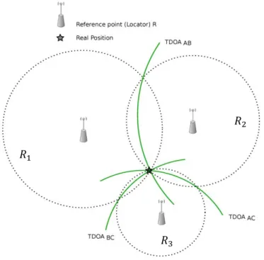
Each TDOA produced has a hyperboloid related to two measuring units where the transmitter must lie on it as in Figure 1-6.
Figure 1-6 Time difference of arrival (TDOA)-based approach. The equation of the hyperboloid is given by:
, (3)
Where , , and , , represent the fixed receivers i and j; and (x, y, z)
represent the coordinate of the location. The easier solution for the hyperbolic TDOA equation shown in (3) is to linearize the equations through the use of a Taylor-series expansion and create an iterative algorithm [35]. To estimate a 2-D location of the location as shown in Figure 1-6, two hyperbolas are formed from TDOA measurements at three fixed
measuring units , , .
Phase Of Arrival (POA) 1.4.1.3
The phase of arrival (POA) [36] has the same concept than the TDOA, except that it depends on the phase carrier (or phase difference) to estimate the range in the narrowband signal. To explain the concept of POA let us see Figure 1-7. Two RUs 1 and 2 are placed at particular locations. The MU emit sinusoidal signal with frequency f, in order to determine the phases of the signal received at each RU. The transmitted signal reaches each RU after a
TDOA which leads to a POA 2 . Then the POA based positioning system is able
to adopt the algorithms using TDOA measurement to locate the MU. However POA needs unwrapping solutions to solve the ambiguity problem.
Figure 1-7: Principle of carrier phase interferometry.
Round Trip of flight (RTOF) 1.4.1.4
The main concept of this method is to use common radar approach. Several RUs acting as transponders respond to the interrogating signal sent by the MU, which measures the roundtrip propagation time as illustrated in Figure 1-8. Notice that its range measurement mechanism is similar to TOA, except that RTOF performs easily the above synchronization since the MU acts as a collocated transmitter and receiver.
The difficulty is to know what is the exact delay/processing time caused by the RUs. It could be ignored in long-range or medium-range systems, where it has to be taken into account for short-range systems. An algorithm to measure RTOF of wireless LAN packets is presented in [37] with the result of measurement error of few meters.
Received signal strength (RSS) 1.4.1.5
By measuring the attenuation of emitted signal strength, it could be possible to estimate the distance of the MU from some set of RUs, where signal attenuation has a relationship with the path loss. Comparing between the transmitted signal strength and the received signal strength, results into a range estimate for free space scenario. Multipath fading and shadowing has an effect on this method, so it can be improved by utilizing the premeasured RSS contours centered at the receiver [38] or multiple measurements at several base stations.
Angle of arrival (AOA) 1.4.1.6
Also called the Direction of Arrival (DOA) is commonly referred to as Direction Finding (DF). In this method, each RU is a center of a circle where the MU lies. Two RUs form pairs of angle direction lines, and then the location of the MU can be found in the intersection of these lines, as shown in Figure 1-9.
For 3-D location, AOA methods use at least three known RUs (A, B, C), and three
measured angles , , to derive the position of the MU. A big advantage of AOA is that no
times synchronization between MU and RUs are required.
Figure 1-9: Basic AOA positioning.
The drawback of AOA measurements is that the quality of the final position estimate degrades rapidly as the MU moves away from the RU, and needs relatively large antennas or antenna arrays. More detailed discussions on AOA estimation algorithms and their properties are provided in [39]. b a ( ,y ) ( ,y ) ( ,y ) c Reference Unit Mobile Unit position Actual angles of a, b, c
B
A
We summarize in Table 1-1 the comparison of these metrics :
Table 1-2 Comparison of RF metrics.
Criteria AOA TOA TDOA RSS
Position Estimation
The intersection of several pairs of angle direction lines
The distance is directly proportional to time taken by the signal to go from the target to references.
Multiple intersected hyperbolas related to the delta in time between the signal’s arrivals at multiple references.
The distance is inversely proportional to received signals strength from several references at the target.
2D space At least two reference nodes
3D space At least three reference nodes At least four reference nodes
Synchronization
Lower requirement in terms of clock precision
All nods have to be precisely
synchronized
Only the reference nodes need to be synchronized
Not required
Issues
Small errors in angle measurement egatively impact accuracy [40].
Relative clock drift between sender and receiver.
Lower accuracy than TOA with the same system geometry. Sensitive to channel inconsistency, Require short distances between nodes. Advantages
the receiver does not need to maintain phase coherence with the time source [41].
It is the most accurate technique, if precise synchronization achieved [42] [40].
It needs only to synchronize the base stations participating in the positioning [40] [43].
It is simple to deploy, there is no need for specialized hardware at the mobile station [44].
Disadvantages
Require costly and large dimensions of antenna arrays. As the distance from the source increases, the position accuracy decreases [45].
It is complex to implement [10], it requires precise time synchronization of all the devices which is high cost [40] [43].
It needs some prior knowledge to eliminate the position ambiguity [40], it is affected by multipath of signals [40]. The establishment of accurate indoor propagation model is very difficult. [43], and affected by environmental dynamics [46].
Scene Analysis
1.4.2
Scene analysis based on RF signal is done by collecting features (fingerprints) of a scene, then matching them with one taken before. RSS-based location fingerprinting is commonly used in scene analysis.
Location fingerprinting consists of two stages: offline stage and online stage. In offline stage collecting signal strengths from nearby base stations/measuring units are done. During the online stage, the currently observed signal strengths and previously collected information are used by a location positioning technique.
We mention four location fingerprinting-based positioning algorithms using pattern recognition technique: K-nearest-neighbor (KNN) [47], neural networks [48], support vector machine (SVM) [49] - [50], and smallest M-vertex polygon (SMP) [51].
Proximity
1.4.3
This technique is one of the simplest algorithms to implement and is already in use today. Locate a MU is done with respect to a well-known dense grid of antennas. A MU is considered to be at the same place as the antenna that receives the strongest signal from it.
One of the most particular examples is the Cell Identification (Cell-ID) or Cell Of
Origin (COO) method. The systems using IR and RFID are also often based on this method.
In RFID systems, RFID scanners are installed to cover all the area, the presence of the object in a one scanner area is used to determine the location of the object.
Conclusion
1.4.4
Whatever the considered metric and the proposed commercially available system, all these kinds of solutions, methods, and systems are well performing but not in dense multipath environments such as indoor scenarios. Hence it is very important to imagine alternative solutions that can work seamlessly either for outdoor or indoor applications. To attain this ultimate goal called “continuity of localization”, important research must be directed toward multiple ways dealing mainly with accuracy and precision but also with granularity and scale, relative or absolute positioning, mobile or fixed objects, infrastructure and cost, co-existence with communication systems.
Objectives
1.5
The presented brief overview shows a clear advantage for RF solutions due to their properties of propagation. It also points out that location estimation is more robust and more precise if the metric used is based on time measurement.
Based on these facts, we develop original research to improve the time delay measurement techniques. In order to release the constraints due to accurate synchronization between RU and MU, we do not consider TOA but TDOA. Which doing so, one should however observe accurate synchronization between the different RUs. This can be made easily if we consider that all the RUs are close to each other, in the way that they can be connected wired. We call this scenario collocated RUs.
We also mention that the proposed solution, which requires wideband signals, should be performed without demanding new infrastructures and may use the already existing popular communication signals and standards. Doing so, one can claim a dedicated infrastructure free solution based on multicarrier communication and especially on Orthogonal Frequency Division Multiplexing (OFDM) signal. The following block diagram shown in Figure 1-10, summarizes the considered scenario.
Figure 1-10: General block diagram the proposed method.
The main objective of this thesis is therefore to extract, for self-positioning purpose and from channel estimation, very small TDOA, compared to the bandwidth of interest. Indeed the proposed approach attempts to minimize the amount of bandwidth for the considered TDOA of interest.
Starting with the communication part, we develop a good knowledge of the communication relevant parameters dealing with – for example – SNR, multicarrier implementation, roll off factor, accepted BER, type of modulation…etc, and then we formulate the problem based on the estimation of channel state information (CSI) to allow simultaneously the localization, by means of TDOA estimation, and the communication.
OFDM Signal source Channel estimation TDOA estimation
The performance of the proposed TDOA estimator is evaluated by both numerical simulations and experimental results. They will be illustrated in the following chapters which give high precision compared with the classical methods.
Conclusion
1.6
Personal Networks require various types of context aware communications to offer flexible and adaptive services. It provides, into one single network, a private and user-centric solution by combining all users’ personal devices at various places in different types of networks. One of the important information, in this context, is location, which enables, tracking, navigation, monitoring, and other location-aware services to make everyday life smart and more secure.
We presented in this chapter, the system architectures and working principles of different existing IP Systems that have been classified into four categories. We gave their performance and suggested to target dedicated infrastructure free IP solutions based on TDOA and able to provide at short-term accurate location.
Bibliography
[1] https://uk.nec.com/en_GB/emea/about/neclab_eu/projects/magnet.html [2] M. Vossiek, L. Wiebking, P. Gulden, J. Wieghardt, C. Hoffmann and P. Heide, "Wireless Local Positioning," IEEE Microwave magazine, vol. 4, no. 4, pp. 77‐86, 2003. [3] K. K. Muthukrishnan, M. Lijding and P. J. Havinga, "Towards Smart Surroundings: Enabling Techniques and Technologies for Localization," International Symposium on Location‐ and Context‐Awareness, pp. 350‐362, 2005. [4] I. G. Niemegeers and S. M. H. d. Groot, "Research issues in adhoc distributed personal networking," Wireless Personal Communications, vol. 26, no. 2‐3, pp. 149‐167, 2003. [5] M. Dru and S. Saada, "Location‐based mobile services: The essentials," Alcatel Telecommunications Review, pp. 71‐76, 2001. [6] S. Bush, "A Simple Metric for Ad Hoc Network Adaptation," IEEE Journal on Selected Areas in Communications, vol. 23, no. 12, pp. 2272 ‐ 2287, 2005. [7] E. Yanmaz and O. K. Tonguz, "Location Dependent Dynamic Load balancing," GLOBECOM '05. IEEE Global Telecommunications Conference, p. 5, 2005. [8] H. Tannous, D. Istrate, A. Benlarbi‐Delai, J. Sarrazin, M. Idriss, M.‐C. H. B. Tho and T. T. Dao, "Exploring various orientation measurement approaches applied to a serious game system for functional rehabilitation," Engineering in Medicine and Biology Society (EMBC), 2016 IEEE 38th Annual International Conference of the, 2016. [9] B. Hofmann‐Wellenho, H. Lichtenegger and J. Collins, "Global Positioning System Theory and Practice," 2001. [10] H. Liu, H. Darabi, P. Banerjee and J. Liu, "Survey of wireless indoor positioning techniques and systems," IEEE Transactions on Systems, Man, and Cybernetics, Part C (Applications and Reviews), vol. 37, no. 6, pp. 1067‐1080, 2007. [11] X. Fernando, S. Krishnan, H. Sun and K. Kazemi‐Moud, "Adaptive denoising at Infrared wireless receivers”,," Proc. SPIE, vol. 5074, 2003. [12] R. Want, A. Hopper, V. Falcao and J. Gibbons, "The Active Badge LocationSystem," ACM Trans. Information Systems, vol. 10, no. 1, pp. 91‐102, 1992. [13] R. States and E. Pappas, "Precision and repeatability of the Optotrak 3020 motion measurement system," J. Medical Engineering and Technology, vol. 30, no. 1, pp. 1‐16, 2006. [14] N. Priyantha, A. Chakraborty and H. Balakrishnan, "The cricket location‐ support system," Proc. ACM Conference on Mobile Computing and Networking, 2000.[15] E. Aitenbichler and M. Mhlhuser, "An IR Local Positioning System for Smart Items and Devices," Proc. 23rd IEEE International Conference on Distributed Computing Systems Workshops (IWSAWC03), 2003. [16] A. Ward, A. Jones and A. Hopper, "A New Location Technique for the Active Office," IEEE Personal Communications, vol. 4, no. 5, pp. 42‐47, 1997. [17] N. Priyantha, A. Chakraborty and H. Balakrishnan, "The cricket location‐ support system," Proc. ACM Conference on Mobile Computing and Networking, 2000. [18] "Sonitor System Website, 2008, http://www.sonitor.com/". [19] J. Hightower and G. Borriello, "A Survey and Taxonomy of Location Systems for Ubiquitous Computing," Technical Report UW‐CSE 01‐08‐03, 2001. [20] H. D. Chon, S. Jun, H. Jung and S. W. An, "Using RFID for Accurate Positioning," Proc. International Symposium on GNSS, 2004. [21] S. Thongthammacharl and H. Olesen, "Bluetooth Enables In‐door Mobile Location Services," Proc. Vehicular Technology Conference, vol. 3, pp. 2023‐2027, 2003. [22] J. C. F. Michel, M. Christmann, M. Fiegert, P. Gulden and M. Vossiek, "Multisensor Based Indoor Vehicle Localization System for Production and Logistic," Proc. IEEE Intl Conference on Multisensor Fusion and Integration for Intelligent Systems, pp. 553‐558, 2003. [23] D. Niculescu and R. University, "Positioning in Ad Hoc Sensor Networks," IEEE Network Magazine, vol. 18, no. 4, pp. 24 ‐ 29, 2004. [24] S. J. Ingram, D. Harmer and M. Quinlan, "UltraWideBand Indoor Positioning Systems and their Use in Emergencies," Proc. IEEE Conference on Position Location and Navigation Symposium, pp. 706‐715, 2004. [25] E. B. B. T. O. S. F. Raab and H. R. Jones, "Magnetic Position and Orientation Tracking System," IEEE Trans. Aerospace and Electronic systems, Vols. AES‐15, no. 5, pp. 709‐718, 1979. [26] S. H. B. M. B. B. M. H. a. S. S. J. Krumm, "Multi‐Camera Multi‐Person Tracking for Easy Living," Third IEEE International Workshop on Visual Surveillance, 2000. [27] D. S. A. Madhavapeddy and R. Sharp, "Context‐Aware Computing with Sound," Proc. 5th Intl Conference on Ubiquitous Computing, 2003. [28] S. Z., J. G. and H. C, "Theoretical and Mathematical Foundations of Computer Science," A Survey on Indoor Positioning Technologies, p. 198–206, 2011. [29] M. R., "Indoor Positioning Technologies," Ph.D. Thesis.Institute of Geodesy and Photogrammetry,ETH Zurich, 2012.
[30] H. J. and B. G., "Location systems for ubiquitous computing," IEEE Comput., vol. 34, pp. 57‐66, 2001. [31] L. J., S. D. and L. K., "Indoor navigation system based on omni‐directional corridorguidelines," Proceedings of the 2008 International Conference on Machine Learning and Cybernetics, pp. 1271‐1276, 2008. [32] M. Kanaan and K. Pahlavan, "A comparison of wireless geolocation algorithms in the indoor environment," Proc. IEEE Wireless Commun.Netw. Conf, vol. 1, pp. 177‐182, 2004. [33] B. Fang, "Simple solutions for hyperbolic and related position fixes," IEEE Transactions on Aerospace and Electronic Systems, vol. 26, no. 5, pp. 748‐753, 1990. [34] C. Drane, M. Macnaughtan and C. Scott, "Positioning GSM telephones," IEEE Communications Magazine, vol. 36, no. 4, pp. 46‐54, 1998. [35] K. Pahlavan, X. Li and J. Makela, "Indoor geolocation science and technology," IEEE Commun. Mag., vol. 40, no. 2, pp. 112‐118, 2002. [36] A. Teuber, B. Eissfeller and T. Pany, "A Two‐Stage Fuzzy Logic Approach for Wireless LAN Indoor Positioning," Position, Location, And Navigation Symposium, 2006 IEEE/ION, 2006. [37] D. J. Torrieri, "Statistical theory of passive location systems," IEEE Transactions on Aerospace and Electronic Systems, Vols. AES‐20, no. 2, pp. 183‐198, 1984. [38] B. V. Veen and K. Buckley, "Beamforming: A versatile approach to spatial filtering," IEEE ASSP Magazine, vol. 5, no. 2, pp. 4‐24, 1988. [39] Z. Farid, R. Nordin and M. Ismail, "Recent advances in wireless indoor localization techniques and system," Journal of Computer Networks and Communications, 2013. [40] J. Friedman, A. Davitian, D. Torres, D. Cabric and a. M. Srivastava, "Angle‐of‐arrival‐assisted relative interferometric localization using software defined radios," In Military Communications Conference,, pp. 1‐8, 2009. [41] Y. Gu, A. Lo and I. Niemegeers, "survey of indoor positioning systems for wireless personal networks," Communications Surveys & Tutorials, vol. 11, no. 1, pp. 13‐32, 2009. [42] Z. Song, G. Jiang and C. Huang, "A survey on indoor positioning technologies.," In Theoretical and Mathematical Foundations of Computer Science, pp. 198‐206, 2011. [43] K. Kaemarungsi and P. Krishnamurthy, "Properties of indoor received signal strength for wlan location fingerprinting," In Mobile and Ubiquitous Systems: Networking and Services, pp. 14‐23, 2004. [44] C. N. Reddy and M. B. Sujatha, "Tdoa computation using multicarrier modulation for sensor networks," International Journal of Computer Science & Communication Networks, vol. 1, no. 1,
2011. [45] C. Wu, Z. Yang, Y. Liu and W. Xi, "Will: Wireless indoor localization without site survey," Parallel and Distributed Systems IEEE Transactions, vol. 24, no. 4, pp. 839‐848, 2013. [46] P. Bahl and V. N. Padmanabhan, "RADAR: An in‐building RF‐based user," Proc. IEEE INFOCOM, vol. 2, pp. 775‐784, 2000. [47] S. Saha, K. Chaudhuri, D. Sanghi and P. Bhagwat, "Location determination of a mobile device using IEEE 802.11b access point signals," Proc. IEEE Wireless Commun. Netw. Conf, vol. 3, pp. 1987‐1992, 2003. [48] B. Ottersten, M. Viberg, P. Stoica and A. Nehorai, "Exact and large sample ML techniques for parameter estimation and detection in array processing," Radar Array Processing pp 99‐151. [49] N. Cristianini and J. Shawe‐Taylor, "An Introduction to Support Vector Machines," 2000. [50] J. M.I., N. Robert and S. Bernhard, "The Nature of Statistical Learning Theory," 2000.
Chapter 2: Multi carrier communication signals
Introduction
2.1
This chapter is the first main part of our work in the sense that, first we develop here the whole Multicarrier (MC) OFDM communication bench, leading later to TDOA measurement, and then discuss the impacting parameters such as SNR, rolling factor, pilots...
Previously and in order to position our work relatively to other multi carrier techniques leading to positioning, we give first a brief overview of those specific positioning methods. We then develop the mathematical derivation and describe the well-known features dealing with digital modulation and coding by considering transmitter and receiver parts. We also give the main technique already used to compensate multipath effects and to evaluate SNR. Let’s precise, that the most used processes here have been performed using MATLAB. We expect that the results obtained can provide a useful reference material for future measurements provided in chapter 4.
General principle of MC based TDOA estimation
2.2
The general communication block diagram dealing with TDOA estimation process is illustrated in the Figure 2-1.
Figure 2-1: The block diagram of TDOA estimation
Multiple OFDM signals travel through the channel toward the receiver. Once the main communication parameters (SNR, Roll of factor etc.) properly defined and evaluated, one can perform, at the receiving part, energy detection or channel estimation to extract the useful TDOA, i.e., time difference of arrival, between the receiver and the OFDM sources.
As it will be demonstrated in chapter III, received power and the channel behavior are directly impacted by TDOA, and of course by the other communication environmental factors. So some practical solutions will be suggested to reinforce the effect of useful TDOA
Channel parameters
LOS, NLOS, ISI
OFDM sources Communication parameters SNR,β…etc. Receiver and TDOA extraction
and to reduce the negative effects of the communication environmental factors. So each part and process of the multicarrier communication system has to be studied clearly to find out whether its influence on the precision of the proposed method is good or not.
Multi carrier based positioning systems and OFDM solutions
2.3
For communications issues, and due to evident reasons linked to redundancy principle, the structure of the multicarrier systems is more powerful, against the multipath channel, than any single carrier schemes. It also seems, due to the relative bandwidth, well suited for the time delay based location device. The following sections present a short overview of multicarrier based positioning solutions.
Blind solution
2.3.1
Many references cited in [1] underline the fact that, in a given network, each sensor independently can identify boundaries in a received MC signal, by looking for the repetition of a given sequence in this signal. Then it can calculate some statistical features (e.g., the sample mean or variance) of each sequence, and transmit, for positioning purpose, the sequence repetition times and the associated feature values to another sensor. This approach, which does not require any knowledge of the transmitted signal, is defined as blind, and is well suited for OFDM based communication. Indeed, in OFDM format, the insertion of a cyclic prefix (CP) before each sequence of data makes the beginning and the end of each sequence identical, leading to the notion of repeated sequence and hence can allow, as mentioned former, the blind identification. Let’s note that for our purpose, CP leads also to the concept of circular convolution, which is of great interest to handle, in an easy way, OFDM signal both in the time domain and in the frequency domain.
Training solution
2.3.2
At the opposite side, there are several other papers in the literature that perform positioning by using a specially designed training MC signal. For example, the work reported in [2], based on the Schmidl–Cox [3] and Minn [4] synchronization algorithms, uses such a cooperative scheme, and with the same concept, the authors in [5] uses, for accurate positioning, cooperative transmitters and receivers in an indoor positioning system. With using of a known transmitted signal, the authors in [6] look for time delay induced by phase
rotations across subcarriers at the receiver. With the same way in IEEE 802.11a wireless LANs, the authors in [7] and [8] correlate the received signals with a training sequence.
Alternative solution
2.3.3
Two other positioning methods are tangentially relevant since they involve multi carrier signals. First in [9], the authors combine the standard TDOA positioning with Cell ID positioning. Recall that the Cell ID method works only if the received power levels indicate that the mobile is within the base station scope of coverage. Second in [10], the extraction of both time of arrival and direction of arrival information is done using several receivers; each of them has an antenna array. All the measurements from all antennas of all receivers are available, at all times, in a central station. Moreover, training data is assumed to be available and will help to solve location problem.
OFDM based positioning
2.3.4
Generally, the positioning methods using OFDM signals in the existing literature are divided into two categories. The first category locates the boundaries of OFDM signals by using the traditional or improved timing synchronization algorithms [11], [12] [13]. The idea behind those methods is to deal with timing synchronization as with the TDOA estimation. Essentially, timing synchronization and TDOA estimation are the same tasks for the receiver. However, the sampling rate limits the accuracy of such methods, and generally, an error of several meters is expected. The second category uses modern spectral estimation techniques [14], [15], [16] and deals with the high-resolution algorithms such as multiple signal classification MUSIC, ESPRIT. These algorithms are applied to the frequency-domain channel estimation to extract a more accurate estimate of the first path in the time domain. Again, the sampling rate limits these mathematical methods that are, by the way, too sensitive to the model. However their accuracy is much better than that of the first category.
Conclusion
2.3.5
To conclude this very brief overview, positioning systems using the multicarrier techniques are mainly based on locating the boundaries of each received signal. The idea behind that is to find the time delay of each received signal, then collecting all the data in a centralized unit. In our knowledge, none of them exploits CSI. As mentioned, several limits and problems need to be solved prior to any deployment. It then seems clear that a deep study
and understanding of how building up the multicarrier signal, for location or time delay issues, have to be done. So the next sections are focused on the main steps of multicarrier digital signal implementation and the effects of the main communication parameter on its performance regarding the TDOA purpose.
Data modulation
2.4
One of the basic elements in the communication system is the symbol, which we need to transmit and receive correctly. The environment of the communication system affects the symbol, leading to channel effect. Therefore, the most active way to find the communication system behavior is to observe the change over this symbol. There are many ways to construct the symbol, which is known as modulation process. Among all of modulation methods, we chose QPSK modulation. In fact, for our purpose, there is no difference to choose any other modulation method.
QPSK Based Communication System
2.4.1
Let us take data-In as a train of symbols 0 , . . . , 1 , where each symbol
is represented by one of 2 possible sequences bits. Therefore the equivalent
expression for is:
2 1 2 1 (4)
A is the amplitude. In QPSK modulator, 2 bits leading to represent in one of the
following set (00, 01, 11, 10) for each k = 0,1,2,3 respectively.
We summarize in Table 2-1 the four symbol mapping definitions for QPSK, the expression of and the amplitude of I-Q signals.
Table 2-1 QPSK symbol mapping definition
Symbol Bits s(t) Phase (Deg.)
00 1/√2 / 45 1/√2 1/√2
01 1/√2 / 135 1/√2 1/√2
11 1/√2 / 225 1/√2 1/√2