HAL Id: tel-02492193
https://tel.archives-ouvertes.fr/tel-02492193
Submitted on 26 Feb 2020HAL is a multi-disciplinary open access archive for the deposit and dissemination of sci-entific research documents, whether they are pub-lished or not. The documents may come from teaching and research institutions in France or abroad, or from public or private research centers.
L’archive ouverte pluridisciplinaire HAL, est destinée au dépôt et à la diffusion de documents scientifiques de niveau recherche, publiés ou non, émanant des établissements d’enseignement et de recherche français ou étrangers, des laboratoires publics ou privés.
tribo-electret kinetic energy harvesters
Hanlu Zhang
To cite this version:
Hanlu Zhang. Modeling, simulation, and optimization of miniature tribo-electret kinetic energy har-vesters. Mechanical engineering [physics.class-ph]. Université Paris-Saclay, 2019. English. �NNT : 2019SACLC100�. �tel-02492193�
optimization of miniature
tribo-electret kinetic energy harvesters
Thèse de doctorat de l'Université Paris-Saclay préparée à CentraleSupélec École doctorale n°579 Sciences mécaniques et énergétiques, matériaux et géosciences (SMEMAG)Spécialité de doctorat: Science des Matériaux
Thèse présentée et soutenue à Gif-sur-Yvette, le 20 décembre 2019, par
Hanlu Zhang
Composition du Jury: Olivier DOARÉ
Professeur, ENSTA-Paristech Président
Alain SYLVESTRE
Professeur, G2ELAB, Université Grenoble Alpes Rapporteur
Philippe BASSET
Professeur, Université Paris Est / ESIEE Paris Rapporteur
Yamin LEPRINCE-WANG
Professeur, Université Paris-Est Marne-la-Vallée Examinateur
Delong HE
Ingénieur de Recherche, MSSMAT, CentraleSupélec Co-encadrant
Jinbo BAI
Directeur de Recherche, MSSMAT, CentraleSupélec Directeur de thèse
Noëlle GOGNEAU
Chargée de Recherche, C2N, Université Paris-Saclay Invitée
Philippe MOLINIÉ
miniature tribo-electret kinetic energy harvesters
by
Hanlu Zhang
Laboratoire de Méchanique des Sols, Structures et Matériaux
A dissertation submitted in partial satisfaction of the requirements for the
degree Doctor of Philosophy in Materials Science
in CentraleSupélec, Université Paris-Saclay
2019
Université Paris-Saclay
Mots clés : Récupérateurs d'énergie cinétique, Tribo-électrets, Modélisation, Simulation, Optimisation, Modification du potentiel de surface
Résumé : La récupération d'énergie ambiante représente une solution durable et complémentaire, par rapport aux batteries, en termes d'alimenter certains produits électroniques grand public, des réseaux de capteurs distribués sans fil, des dispositifs portables ou implantables, des systèmes "Internet of Things" avec beaucoup de nœuds, etc.. Les mouvements humains et les vibrations mécaniques sont des sources d’énergie les plus disponibles à cet effet. Les dispositifs collectant de l’énergie cinétique à petite échelle sont appelés récupérateurs d'énergie cinétique (RECs). Les RECs avec électrets (E-RECs) sont RECs électrostatiques qui utilisent des électrets (diélectriques avec charges quasi permanentes) comme source de tension de polarisation, et qui peuvent générer de l'électricité grâce à l'effet d'induction électrostatique lorsque la capacitance des E-RECs varie du fait des mouvements/vibrations. L’objectif de cette thèse est d’étudier les caractéristiques de sortie transitoires des E-RECs à la fois par des simulations théoriques et par des mesures expérimentales, et d’optimiser l’efficacité et la puissance de sortie des E-RECs par charge triboélectrique ainsi que d'autres méthodes adaptées à leurs caractéristiques de sortie, qui sont essentielles pour améliorer la performance des E-RECs.
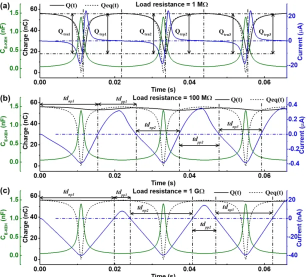
Tout d'abord, les caractéristiques de sortie à amplitude variable d'un E-REC en mode contact-séparation (CS) dans des cycles de travail transitoires sont examinées via les résultats de la simulation basés sur un modèle de circuit équivalent détaillé. Ces caractéristiques de sortie à amplitude variable sont attribuées au décalage du cycle de transfert de charge par rapport au cycle de mouvement d'excitation. Les influences
de la condition initiale et de la résistance de charge sur la variation des pics de tension de sortie d'un tribo-électret REC (TE-REC) en mode CS réalisé avec un film électret en polytétrafluoroéthylène (PTFE) one été étudiées en détail et vérifiées à la fois par simulations et expériences.
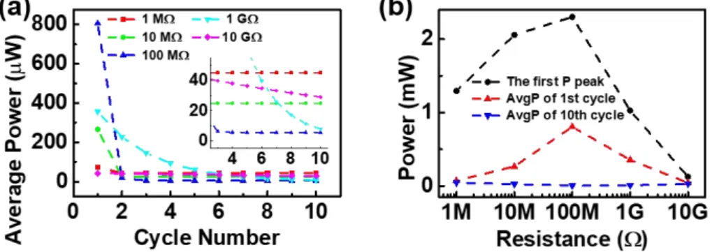
Deuxièmement, une méthode d'optimisation du temps de contact est utilisée pour améliorer la puissance de sortie et l'efficacité du TE-REC en mode CS avec une résistance de charge de 100 MΩ. L'énergie convertie théorique maximale par cycle de travail du TE-REC est analysée. Nous avons aussi étudié les influences de plusieurs facteurs défavorables qui généralement réduiraient la conversion d'énergie par cycle de travail du TE-REC. L’optimisation de l'intervalle d'air maximal et la méthode tribo-charge sont également utilisées pour améliorer la puissance moyenne sortie du TE- REC avec une surface de 4 cm × 4 cm, de ~ 150 μW à ~ 503 μW.
Enfin, une méthode innovante et facile a été développée pour charger le film polymère électret en éthylène propylène fluoré (FEP) par pelage de ruban adhésif, sans utiliser de source de haute tension électrique. La distribution du potentiel de la surface du film de FEP est fortement modifiée après plusieurs pelages au ruban adhésif. Par conséquence, la tension et le courant de sortie des TE-REC fabriqués avec le film FEP traités sont beaucoup améliorés. Pour un TE-REC flexible d’une surface de 64 cm2 soufflé par du vent, une amélioration évidente d'environ 692% de la puissance de sortie, correspondant 2,5 μW à environ 19,8 μW, a été obtenue par cette méthode.
Université Paris-Saclay
Keywords : Kinetic energy harvesters, Tribo-electrets, Modeling, Simulation, Optimization, Surface potential modification
Abstract : Harvesting energy from the ambient environment is a good sustainable and complementary power supply solution in some consumer electronics, distributed wireless sensor networks, wearable or implantable devices, "Internet of Things" systems with lots of nodes, etc. in comparison with batteries. The ubiquitous kinetic energy in various motions and vibrations is one of the most available energy sources for such a purpose. The electret kinetic energy harvesters (E-KEHs) is one type of electrostatic kinetic energy harvesters using electrets (dielectrics with quasi-permanent charges) as the biasing voltage source, which can generate electricity based on the electrostatic induction effect when the capacitance of the E-KEHs is changed by the motions/vibrations. This thesis aims to investigate the transitory output characteristics of E-KEHs by both theoretical simulations and experimental measurements and to optimize the efficiency and output power of E-KEHs by tribo-charging and other methods adapted to their output characteristics, which are significant to improving the performance of E-KEHs.
Firstly, the amplitude-variable output characteristics of a contact-separation (CS) mode E-KEH in transitory working cycles are investigated via the simulation results based on a detailed equivalent circuit model. These amplitude-variable output characteristics are attributed to the lag of the charge-transfer cycle behind the excitation motion cycle. The influences of both the initial condition and the load resistance on the variation in the output voltage peaks of a tribo-electret KEH (TE-KEH) are studied in detail and verified by both simulated and experimental data of a CS mode TE-KEH made with polytetrafluoroethylene (PTFE) electret film.
Secondly, based on the analysis of the amplitude-variable output characteristics, a contact time optimization method is used to improve the output power and efficiency of the CS mode TE-KEH with a large load resistance of 100 MΩ. The theoretical maximum output energy per working cycle of the TE-KEH is analyzed. Several usually unfavorable factors that would reduce the practical output energy per working cycle of the TE-KEH are discussed. The maximum air gap optimization and the tribo-charging methods are also used together to further improve the average output power of the 4 cm × 4 cm sized TE-KEH from ~150 μW to ~503 μW.
At last, an innovative and facile tape-peeling tribo-charging method is developed to charge the fluorinated ethylene propylene (FEP) polymer film to make electrets without using any high voltage source. The surface potential distribution of the FEP film is apparently changed after several tape-peeling tribo-charging treatments. Consequently, the output voltage and current of TE-KEHs made with the FEP film are greatly improved. For a 64 cm2 sized flexible TE-KEH to harvest kinetic energy from wind, an apparent ~692% improvement in the output power from ~2.5 μW to ~19.8 μW was obtained by the tape-peeling charging method.
First, I would like to express my sincere gratitude to my supervisor Prof. Jinbo Bai for giving me the opportunity to do this research and for his guidance always with patience and encouragement during my doctoral study. Special gratitude is also given to my co-supervisors Dr. Delong He and Prof. Philippe Molinié. They gave me many inspiring suggestions and help in experimental implementations. Every discussion with them is helpful to me. It would be impossible to finish this thesis without their guidance and supports.
Then I would thank all the jury members of my thesis defense: the chairman Prof. Olivier Doaré, two reporters Prof. Alain Sylvestre and Prof. Philippe Basset, the examiner Prof. Yamin Leprince-Wang, and the invited member Madame Noëlle Gogneau. All their comments and questions especially those in the reports are instructive in improving the quality of this thesis.
I am grateful to the staffs at the laboratories of MSSMat, SPMS, and LGPM. Special gratitude is extended to Mr. Éric Perrin for his help in setting up the linear motor system, to Nicolas Roubier for his help in repairing the measurement programs of electrometers, to Madame Farida Djebarri for her help in purchasing the surface voltmeter and other experimental materials, to Mr. Gilbert Le Gal for fabricating designed mechanical components, to Madame Pascale Gemeiner for her help in Raman measurements, to Mr. Vincent Butin for his help in FT-IR measurements, to Mr. Xavier Bril and Mr. Paul Haghi-Ashtiani for their help in trial experiments of charging electrets by thermo-charging or cold plasma, and to Madame Fleur Litoust and Mr. Daniel Kervern for their kindly help in many aspects during my stay at MSSMat.
I also owe my sincere gratitude to my colleagues and friends in France: Yu Liu, Yiguo Xu, Minhao Yang, Anne Zhang, Shan Feng, Benhui Fan, Chaohe Hu, Li Gong, Na Cui, Jing Zhang, Yuanyuan He, Yuzhu Wang, Guang Zhu, et al. Their help, encouragement, and companionship gave me a precious period full of joy in France.
Meanwhile, I would also like to express my gratitude to China Scholarship Council (CSC) for the financial support to my study in France.
Acknowledgements... I Table of content... III Abbreviations and Symbols... VI
Chapter 1 General background and introduction... 1
1.1 Background... 1
1.2 Different types of kinetic energy harvesters (KEHs)... 2
1.2.1 Electromagnetic KEHs...2
1.2.2 Piezoelectric KEHs... 5
1.2.3 Electrostatic KEHs... 6
1.2.4 Comparisons among different types of KEHs...9
1.3 Motivations and the outline of this thesis...10
Chapter 2 Introduction to electrets and electret kinetic energy harvesters... 13
2.1 Overview... 13
2.2 Electrets... 13
2.2.1 Physical fundamentals...13
2.2.2 Charging methods... 16
2.3 Basic principle and early researches of electret kinetic energy harvesters (E-KEHs)... 17
2.3.1 Basic principle...17
2.3.2 Early researches...18
2.3.2.1 Electret transducers with variable capacitances... 18
2.3.2.2 Electret generators without variable capacitance... 21
2.4 Different structures of E-KEHs with variable capacitances... 22
2.4.1 A general introduction to E-KEHs with the parallel-plate configuration... 22
2.4.2 Cellular/foam/porous piezo-electrets/ferro-electrets...24
2.4.3 Triboelectric nanogenerator (TENG) or tribo-electret kinetic energy harvester (TE-KEH) with diverse structure designs... 26
2.4.4 Direct motion-driven mode and undirect vibration-driven mode... 28
2.5 Different analysis models for E-KEHs with variable capacitances... 30
2.5.1 The compact equivalent electrical model for direct motion-driven E-KEHs ...30
2.5.2 The electromechanical model for undirect vibration-driven E-KEHs... 33
2.5.2.1 A general 1 degree-of-freedom linear damping model for vibration mechanic analysis... 33
2.5.2.2 A complete electromechanical model for vibration-driven E-KEHs... 37
2.5.2.3 Lumped-parameter equivalent circuit model...39
3.1 Introduction...44
3.2 Analytical solution of the detailed equivalent electrical model for a contact-separation mode E-EKH...44
3.2.1 The analytical solution with arbitrary initial conditions... 44
3.2.2 The initial electric equilibrium assumption...47
3.2.3 The short-circuit current and the open-circuit voltage...48
3.3 Simulation results and discussion... 48
3.3.1 Parameters for the simulation...48
3.3.2 Charge-transfer process...50
3.3.3 Amplitude-variable output current/voltage/power...53
3.3.4 Simulations with another initial condition... 57
3.3.5 QV cycle analysis...62
3.4 Experimental and simulation verifications...64
3.4.1 Experimental Methods... 64
3.4.2 Estimations of parameter values for corresponding simulations... 66
3.4.3 Results and discussion...69
3.5 Chapter conclusion... 70
Chapter 4 Optimizing the output power of the contact-separation mode TE-KEH ...72
4.1 Introduction...72
4.2 Optimization of the contact time...72
4.2.1 Experimental results...72
4.2.2 Simulation results...76
4.3 The maximum theoretical output energy per working cycle of the TE-KEHs with switch controlling...80
4.3.1 Parallel-connected switch-controlled working cycles...80
4.3.2 Series-connected switch-controlled working cycles... 81
4.4 Several usually unfavorable factors that would reduce the practical output energy per working cycle of the TE-KEH... 84
4.4.1 The microscale incomplete surface contact... 84
4.4.2 The electric breakdown... 87
4.4.3 The parasitic capacitance and the fringe capacitance...89
4.5 Other optimizations... 90
4.5.1 Tribo-charging...90
4.5.2 Optimization of the maximum air gap... 91
4.6 Chapter Conclusion... 93
Chapter 5 Tape-peeling tribo-charged FEP film-based TE-KEHs... 96
5.1 Introduction...96
5.2 Material properties... 96
5.3.2 Tape-peeling charging process...98
5.4 Results and discussion... 99
5.4.1 Improving the performance of the TE-KEH by the tape-peeling charging method...99
5.4.2 Surface potential mapping...104
5.4.3 Demonstration of harvesting energy from wind and human motions...107
5.5 Chapter conclusion... 110
Chapter 6 General conclusions and perspectives...113
6.1 General conclusions...113
6.2 Remarks and perspectives... 114
6.2.1 Remarks on simulations and power managements of E-KEHs...114
6.2.2 Future work... 116
References... 118
Abbreviations
AC Alternative Current
Al Aluminum
AlN Aluminum Nitride
Au Gold
BT Barium Titanate
CDRG Coulomb-Damped Resonant Generator CE Contact Electrification
CFPG Coulomb-Force Parametric Generator CMEO Cycles for Maximized Energy Output CS Contact-Separation
Cu Copper
DC Direct Current DE Dielectric Elastomer DOF Degree of Freedom EG Electret Generator
E-KEH Electret Kinetic Energy Harvester EM Electromagnetic
ES Electrostatic
FEP Fluorinated Ethylene Propylene
FT-IR Fourier Transform Infrared Spectroscopy IoT Internet of Things
KEH Kinetic Energy Harvester
KERS Kinetic Energy Recovery System MEMS Micro-Electro-Mechanical System PDMS Polydimethylsiloxane
PE Piezoelectric
PENG Piezoelectric Nanogenerator PTFE Polytetrafluoroethylene PVDF Polyvinylidene Fluoride PZT Lead Zirconated Titanate
SEM Scanning Electron Microscope TE Tribo-electret
TEG Triboelectric Generator TENG Triboelectric Nanogenerator
VDRG Velocity-Damped Resonant Generator WSN Wireless Sensor Network
ZnO Zinc Oxide
Symbols
a acceleration (m/s2)
AvgP average output power (W)
C capacitance (F)
d0 effective dielectric thickness (m)
dof effective dielectric thickness of the electret film (m)
d the piezoelectric strain coefficient tensor (pC/N)
D damping coefficient (Ns/m) D electric displacement (C/m2) δ strain tensor E electromotive force (V) E electric field (V/m) ε0 vacuum permittivity (~8.85×10⁻¹²F/m) εr dielectric constant g gravitational acceleration (m/s2) I current (A) magnetic flux (Wb) k spring constant (N/m) m mass (kg)
σ effective surface charge density (C/m2)
σ stress tensor (MPa)
P output power (W)
Q charge (C)
t time (s)
T period (s)
V voltage (V)
v motion velocity (m/s)
W energy (J)
Ψ total magnetic flux linkage (Wb) ζ damping ratio
Chapter 1 General background and introduction
1.1 Background
Harvesting energy from the ambient environment is a good choice to prolong the life time or even become the power supply in consumer electronics, distributed wireless sensor networks (WSN), wearable or implantable devices, Internet of Things (IoT) systems with lots of nodes, etc. [1-3]. Especially with the development of electronic technology, electronic devices have a general trend of miniaturization with lower power consumption [4], making it possible to build autonomous self-powered systems powered by energy harvesters, reducing the maintenance and environmental problems caused by drained batteries. Figure 1- 1 shows the comparison of advantages and disadvantages in using batteries and energy harvesters (EHs) in such systems.
Figure 1- 1 Comparison between the battery and energy harvesters in powering IoT or WSN node and implantable devices.
Four main ambient energy sources exist in our environment: radiant energy (light, radio-frequency radiations), mechanical energy (vibrations, movements, and deformations), thermal energy (temperature gradients or variations), and chemical energy (chemistry, biochemistry). Each of them has a different power density range in different environments. The type of energy source to be used should be chosen according to the local environment and the power consumption of the load circuit [5].
Outdoor sunlight is usually considered to be the most powerful ambient energy source as shown in Table 1- 1.
Table 1- 1 Estimated power densities of several energy sources [2, 6].
Energy sources Estimated Power density (μW/cm3) Harvesting method
Solar (outdoors) 150~15000
Photovoltaic Solar (indoors) 6~100
Human walking
Vibrations (human motion) ~330~4 Kinetic energy harvesters(Electromagnetic, Piezoelectric, Electrostatic) Vibrations (machine) ~800
Daily temperature variation ~10 Pyroelectric 10 ℃ temperature gradient ~15 Thermoelectric
However, for some situations without enough light but with abundant mechanical energy sources, kinetic energy harvesters (KEHs) could be suitable for extending the lifetime of power source [2] or building self-powered systems. Different from the kinetic energy recovery system (KERS) which harvests kinetic energy of a vehicle under braking [7], KEHs mainly convert small-scale kinetic energy from motions and vibrations into electricity with the power of microwatt to a milliwatt. And the dimension of KEHs in any direction is usually below 10 cm, that’s why they are usually described as “miniature”. In this thesis, KEHs are defaulted to be miniature without special statement. Three common types of KEHs, i.e. the electromagnetic, piezoelectric, and electrostatic, will be introduced in section 1.2.
1.2 Different types of kinetic energy harvesters (KEHs)
1.2.1 Electromagnetic KEHs
Electromagnetic (EM) generators are basically used almost in every power station except the photovoltaic ones. They are based on Faraday’s law of induction i.e. “The electromotive force around a closed conductive path equals the negative of the
time rate of change of the magnetic flux enclosed by the path.” [8] as expressed by the
equation (1-1), where E is the electromotive force, Ψ is the total magnetic flux linkage enclosed by the conductive path, n is the number of turns of the conductive coil that forms the conductive path, is the magnetic flux enclosed by the conductive coil, t is time.
Electromagnetic KEHs (EM-KEHs) are based on the same fundamentals but with smaller scales. They are made with at least one conductive coil which is relatively movable to at least one magnet, with two typical architectures: magnet in line and magnet across coil [9]. The conductive coil usually has multiple turns to get a considerable electromotive force. And the internal resistance of the electromagnetic KEHs is low due to the conductive nature of the coil. Huge EM generators can output remarkable power at the magnitude up to ~1000 MW [10] by using an intense magnetic field and numerous turns of coils. While for miniature EM-KEHs, the magnetic field and turns of coils are usually constrained by the limitations in the volume, cost, weight, etc., and they are often designed to have a high mechanical quality factor to harvest energy from low-amplitude vibrations, but that leads to a narrow bandwidth of EM-KEHs [11].
To widen the bandwidth of KEHs, Sari et al. [12] designed an arrayed EM-KEH with multiple cantilever-structured coils as shown in Figure 1- 2(a), each with a different cantilever length to get different resonant frequencies. The overall frequency response of the output power of this arrayed EM-KEH was effectively broadened as shown in Figure 1- 2(b). However, due to the small dimensions of each cantilever, the frequency band located at a high-frequency range of about 3400~4600 Hz which is much larger than common vibrations in the ambient environment (mostly lower than 250 Hz) [2]. Halim et al. [13] designed a cylinder non-resonant EM-KEH with two frequency up-converted small generators using spring at the two ends and an inside free-moving ball to harvest energy from low frequency vibrations, as shown in Figure
1- 2(b), with a flat peak-to-peak open-circuit voltage around 2.4 V in the excitation
frequency range of 14~25 Hz. Besides these two designs, Zhu et al. proposed a method of tuning the electrical resonant frequency of the EM-KEH with loading different capacitors to the EM-KEH, but with narrow effective tuning ranges [11].
Figure 1- 2 Diverse miniature EM-KEHs. (a) An arrayed multiple cantilever EM-KEH with its frequency response shown in (b) [12]. (c) An EM-KEH with the inside free-moving ball for energy harvesting from low-frequency vibrations [13]. (d) A spherical EM-KEH with inside free-rolling magnet ball for harvesting energy from irregular human motions [14]. (e) A resonant EM-KEH with 6 degree-of-freedom for harvesting energy from vibrations of multiple directions [15].
Other special structure designs of EM-KEHs include a spherical structure with an inside free-rolling magnet by Bowers et al. [14], as illustrated in Figure 1- 2(d), and using a micro resonant structure with 6 degree-of-freedoms (DOFs) of motions by Liu et al. [15], as shown in Figure 1- 2(e), to harvest energy from multi-directional vibrations. It should be noted that the open-circuit voltage and thus the output power of EM-KEHs are usually low due to the constraints in the magnetic field intensity, the turn number of coils, and the working frequency. Moreover, the complicated structure designs and utilization of multiple materials make EM-KEHs not compatible with massive production processes. It is considered that EM generators are irreplaceable in huge power generations, but EM-KEHs are uncompetitive in harvesting small/micro-scale kinetic energy in comparison with other techniques [2].
1.2.2 Piezoelectric KEHs
In crystalline materials with no inversion symmetry, electric potential can be produced under stress, this is called the piezoelectric effect which was first reported by Jacques and Pierre Curie brothers in 1880 [16], and such materials are termed as piezoelectric (PE) materials. The first well-known application of PE materials is on sonar systems where the inverse PE effect (i.e. the generation of stress by applying electric field) of quartz slice was used to produce ultrasounds. PE materials are usually dielectrics with low conductivity, after depositing with conductive electrodes on their polar directions, they can be used to fabricate KEHs to generate electricity from mechanical stress. Two constitutive equations those describe the PE and reverse PE effects are [2]:
쮀 /푀 (1-2)
쮀 (1-3)
where δ, σ, and d are tensors of the strain, the stress, and the PE strain coefficients, respectively; Y is the Young’s Modulus of the PE material; E and D are vectors of the electric field and the electrical displacement (charge density), respectively.
Two of the PE strain coefficients, d31 and d33, are often used to evaluate the
electromechanical coupling intensity of PE materials. Lead zirconated titanate (PZT) and related inorganic materials with the perovskite crystalline structure are typical piezoelectric materials with high d33 (400~2500 pC/N) [16, 17], but also with high
stiffness [18]. Polyvinylidene fluoride (PVDF) as a piezoelectric polymer has low stiffness but a relative lower d33than piezoelectric ceramics. Nathan S. Shenck and
Joseph A. Paradiso [19] designed an energy harvesting shoe using a PZT dimorph under the heel and a flexible PVDF stave under the ball of the foot to scavenge electricity from human walking, as shown in Figure 1- 3(a). Liu et al. [20] designed a PZT-based EH with two cantilever structures with different resonant frequencies to broaden the operation frequency range and increases the output voltage and power, as shown in Figure 1- 3(b). Wurtzite aluminum nitride (AlN) is another usually used piezoelectric ceramic. Self-powered wireless sensor models based on MEMS AlN piezoelectric EHs had been developed by MicroGen Systems, Inc. [16] as shown in
Figure 1- 3 Diverse miniature PE-KEHs. (a) A piezoelectric EH mounted in a shoe to harvest energy from human walking [19]. (a) A piezoelectric EH based on two cantilever structures with different resonant frequencies. [20] (c) An AlN-based EH model for self-powered wireless sensors [16]. (d) The piezoelectric effect on a single ZnO nanowire [21]. (e) A self-powered wireless sensor system based on ZnO nanowire arrays [22]. (f) Near-filed electrospinning PVDF nanowires with intrinsic high piezoelectric coefficients [23].
Generally, piezoelectric ceramics and polymers need to be polarized to align their dipole directions in different piezoelectric domains before using. While for a single piezoelectric nanowire, piezoelectricity can present without poling treatment, as illustrated in Figure 1- 3(d). Z. L. Wang et al. [21, 24] fabricated piezoelectric nanogenerators (PENGs) based on wurtzite aligned zinc oxide (ZnO) nanowire arrays, they also demonstrated a wireless sensor and transmitter system powered by a ZnO nanowire array PENG [22] as shown in Figure 1- 3(e). PVDF nanofibers prepared by a near-field electrospinning method reported by C. Chang et al were also found to have good piezoelectric performance due to the in situ mechanical stretch and electrical poling during the electrospinning process, as shown in Figure 1- 3(f).
1.2.3 Electrostatic KEHs
Electrostatic (ES) KEHs mainly refer to KEHs based on variable capacitors which are appropriately pre-charged, and kinetic energy is converted to electricity when the pre-charged capacitors have a decrease in the capacitance C due to the relative movement or deformation of their electrodes or inner dielectrics caused by external motions. There are two basic working modes for ES-KEHs. In the constant charge mode schemed in Figure 1- 4(a), the capacitor was firstly charged with a certain amount of charge when C is at the maximum value (Cmax, o→a in the
corresponding QV diagram), then C decreases in the open-circuit condition which means the charge amount keeps constant (a→b), followed by the discharge when C get the minimum value (Cmin, b→o) with transferring electricity to load circuit, then C
goes back to Cmaxto start the next cycle. And in the constant voltage mode schemed in
Figure 1- 4(b), the capacitor is firstly pre-charged to a constant voltage value when C
is at the maximum value (o→a), then discharge occurs with C decreasing and the voltage keeps constant (a→b), finally C goes back to the maximum value to start the next cycle.
Figure 1- 4 Illustrations of (a) the constant charge and (b) the constant voltage working modes of a variable capacitor electrostatic EH with corresponding QV diagrams, reproduced from [25].
For both modes, the ES-KEH output net electric energy that equals the enclosed area of the triangle shape oab in one working cycle. For the constant charge mode, it can be calculated by [26]:
݄ ݎ ݃ ܿ쮀 12( 푀 푀 ) ܿ 푀 푀 (1-4).
And for the constant voltage mode, there is [26]:
݃ ݃ ܿ쮀 12( 푀 푀 ) 2푀 (1-5).
These two modes are two extreme working cycles. In practice, the shape of the QV diagram can be modulated by external conditioning circuits. To implement the constant voltage or charge mode in an ES-KEH, at least two synchronized switches with the switching on-off period same with the variation period of C are necessary
[27]. There are other shapes of the QV cycle of ES-KEHs that can be implemented by simpler conditioning circuits. As illustrated in Figure 1- 5(a), besides the triangle QV cycle shapes for the constant-charge (trace OCB) and constant-voltage (trace OAB), other common shapes of QV cycle of ES-KEH includes the rectangle (trace DFBE) which can be realized by a charge pump [28-30] or a Bennet’s doubler [30-32] or a Cockcroft–Walton voltage multiplier [33, 34] circuit, and the teardrop shape (dotted line trace) which can be realized by continuous conditioning circuit or ES-KEHs with electret layer [35, 36]. Figure 1- 5(b) illustrated successive QV cycles from the first triangle shape to a series of trapezoidal shapes, which can be obtained from an ES-KEH with a pre-charged large reservoir capacitor as the voltage source and with an idealized pre-charged charge pump circuit [27].
Figure 1- 5 (a) Common shapes of the QV cycle of ES-KEHs. (b) Illustration of successive QV cycles from an ES-KEH with an idealized pre-charged charge pump circuit. [27]
During the capacitance variation of the ES-KEHs, kinetic energy is converted to electrostatic energy via the Coulomb’s force which is more significant than Lorenz’s force in micro-scale [25]. In addition, ES-KEHs with variable capacitance structures have good compatibility with MEMS fabrication processes, which is important for batch fabrication with low cost [25, 37]. Therefore, ES-KEHs are more suitable than EM-KEHs to be miniaturized and batch-fabricated to harvest micro-vibration energy. By a simple batch process using only two lithography masks, P. Basset et al. [38] fabricated a micro ES-KEH with an area of about 1 cm2 as shown in Figure 1- 6(a).
The micro interdigit variable capacitance structure of another micro ES-KEH with an overall size of 1 cm × 1.5 cm × 200 µm by Bogdan Vysotskyi et al. [39] is presented in Figure 1- 6(a).
Figure 1- 6 (a) A batch-fabricated micro ES-KEH [38]. (b) Photograph of a micro ES-KEH showing the micro comb variable capacitance structure [39]. (c) Scheme of an ES-KEH using dielectric elastomer [40]. (d) A circuit provides an initial charge to the variable capacitor in an ES-KEH [41]. (e) A dielectric elastomer ES-KEH using electret as the biasing voltage source [42].
Besides micro electrostatic KEHs to harvest energy from vibrations, dielectric elastomers (DE) were used to fabricated relative large electrostatic KEHs [40, 43] to harvest energy from pressure-driven deformations as illustrated in Figure 1- 6(c). However, for those electrostatic KEHs, at least an external initial charge/voltage supply is required to charge the variable capacitor before harvesting energy, as illustrated in Figure 1- 6(d), and a switching or continuous conditioning circuit [27] is usually necessary to control the charge-discharge cycles. Therefore, T. Vu-Cong, T, C. Jean-Mistral, and A. Sylvestre [42, 44, 45] used electrets (quasi-permanently charged dielectrics) to substitute the external charge/voltage source, which greatly simplifies the structure and power management circuits of DE-KEHs. Other electrostatic KEHs using electrets will be further introduced in Chapter 2, section 2.4.
1.2.4 Comparisons among different types of KEHs
Among these three common types of KEHs, S.J. Roundy [2] estimated that the PE-KEHs have the highest practical maximum power density of ~ 17.7 mJ/cm3, the
EM-KEHs and ES-KEHs have the same practical maximum power density of ~4 mJ/cm3. In practice, there are also other factors (e.g. the dimension, the working
frequency, the load circuit) those need to be considered to decide which type of KEHs is more appropriate for specific applications. Several advantages and disadvantages of these three types of KEHs are listed in Table 1- 2.
Table 1- 2 Comparison of advantages and disadvantages of the three types of KEHs.
Type Advantages Disadvantages
Electromagnetic High efficiency; Large Reliability; Low mechanical damping; Small Resistive impedance
Low output voltage for miniature devices; Heavy magnets; Difficult to batch-fabricate miniature devices Piezoelectric High energy density;
Moderate output voltage; Easy to scale down by using nanomaterials
Low efficiency; Pulsed output; High capacitive impedance; Need relatively large forces to deform piezoelectric materials;
Electrostatic High efficiency and open-circuit voltage for miniature devices; Low weight; Compatible with microfabrication
Need pre-charge or biasing voltage; High capacitive impedance; Low output current; Risks of electrostatic adherence and discharge
1.3 Motivations and the outline of this thesis
ES-KEHs using electrets, especially the tribo-charging electrets (tribo-electrets), are the research objects of this thesis. The motivations include understanding the basic working principle of electret-KEHs (E-KEHs) by analytical modeling and numerical simulations, optimizing the output power of tribo-electret KEHs (TE-KEHs) based on the simulation results and experiments, and developing a facile and effective tribo-charging method to charge the electrets.
The general outline of this thesis is as follows. In Chapter 1, the general background and brief introductions and comparisons of three common types of KEHs have been presented. In Chapter 2, physical fundamentals and charging methods for electrets are briefly introduced, and an introduction to the basic principle, early researches, structure designs, and the physical models of E-KEHs is given. In
Chapter 3, the analytical solution of a detailed equivalent circuit model for
contact-separation (CS) mode E-KEHs is given, then the amplitude-variable output characteristics of a CS mode E-KEH during transitory working cycles with different load resistances and initial conditions are studied, the reason for these characteristics are analyzed based on both simulation and experimental results. In Chapter 4, several optimization methods are used to improve the output power of a CS mode TE-KEH,
the maximum theoretical output energy or the TE-KEH is deduced, and several usually unfavorable factors that would reduce the effective output energy per working cycle of TE-KEHs are discussed. In Chapter 5, a novel tape-peeling tribo-charging method is used to charge FEP electret films, the output voltage and current of TE-KEHs based on the FEP films are apparently improved by the tribo-charging method, and the prototype of a flexible FEP-film based TE-KEH is demonstrated to harvest energy from wind and gentle human motions. In Chapter 6, remarks on simulations and power managements of E-KEHs are given, and perspectives on future work related to this thesis are presented.
Chapter 2 Introduction to electrets and electret kinetic
energy harvesters
2.1 Overview
In this chapter, firstly a brief introduction to the physical fundamentals and charging methods for electrets is given in section 2.2, then a more detailed introduction to electric kinetic energy harvesters (E-KEHs) from the basic principle and research history to the different structure designs, driving modes, and theoretical models is presented in section 2.3~2.5.
2.2 Electrets
2.2.1 Physical fundamentals
It is believed that Michael Faraday was the first to outline the basic principles of electrets in 1839 [46], Oliver Heaviside created the word “electret” in 1892 [47], and the systematic research into electrets began in 1919 when a Japanese physicist, Mototaro Eguchi, fabricated an electret by cooling and solidifying molten mixture of Carnauba wax and resin with a little beeswax while applying an electric field of about 10 kV·cm-1to the mixture [48, 49]. In the book Electret published in 1987 [46], G. M.
Sessler gave a general physical definition of electret as: “An electret is a piece of dielectric material exhibiting a quasi-permanent electrical charge. The term "quasi-permanent" means that the time constants characteristic for the decay of the charge are much longer than the time periods over which studies are performed with the electret.”. The motioned “electrical charge” could be “real” excess mono-charges on the surface or in the bulk of materials, or polarizations (frozen-in aligned dipoles for polar, or space charges for both polar and non-polar dielectrics) in the bulk, or a composition of them [46, 50], as illustrated in Figure 2- 1.
Figure 2- 1 Different types of electrical charges in electrets.
The charge decay time constant in electret materials is usually expected to be as large as possible. The concerned “time periods” for studies in electrets are usually counted in hours, days, months, and even years [50]. Dielectric materials with excellent insulating properties are usually good candidates to make electrets since their extremely low conductivities could lead to a quite large charge decay time constant. For instance, it was estimated that a corona-charged polytetrafluoroethylene (PTFE), which is one of the best insulating polymers with low conductivity of ~10-22
Ω-1cm-1[46], could have of charge stability with a lifetime of a few hundred years in a
dry environment [51].
The key issue in studying electret materials is to know how the charge distribution in an electret influence the electric field around it. A general theoretical analysis based on Gauss’s law and the Kirchhoff’s voltage law was also given by G. M. Sessler [46] as shown in Figure 2- 2.
Figure 2- 2 The cross-section view of the general arrangement of a piece of electret with two dielectric gaps and two nearby metal electrodes analyzed by G. M. Sessler [46].
A piece of flat electret sheet in the middle with dielectric constant of εr and
thickness of dfwas to be concerned in the model, with assuming that the dielectrics in
the Gap 1 with dielectric constant of ε1, thickness of d1, and in the Gap 2 with
permittivity of ε2, thickness of d2, cannot be charged, and all lateral dimensions were
across the two electrodes as illustrated in Figure 2- 2 when the switch is open-circuited. With such an arrangement, two significant inferences from Sessler’s analysis will be introduced as follows.
The first one is that any charge distribution in the electret can be regarded as the electret has “projected” or “effective” surface charge distributions when investigating the induced external electric field around it. Assuming an arbitrary volume charge density ρ(x) located at the vertical coordinate x with setting the bottom of the electret as the coordinate 0 as shown in Figure 2- 2, then the corresponding equivalent effect charge density at the bottom and top surfaces of the electret can be calculated by:
1 쮀 1 ( ) () (2-1)
2 쮀 1 () (2-2)
where σ1and σ2are the effective surface charge density at the bottom and top surfaces
of the electret surfaces respectively. The volume charge density ρ(x) includes the “real” mono-charge density and gradient of the dipole polarization or microscopic charge displacement in the electrets [46]. All the planar charge density in this thesis refers to the effective surface charge density without a specific declaration.
The second one is that the electric field strength in the two gaps and in the electret can be calculated by:
1쮀 1 ( 1 1 1 2( 1 2) 1 2 ) (2-3) 2쮀 1 ( 22 2 1( 11 2 2)) (2-4) ( ) 쮀 1 ( 1 1 2 1 2 2 2 2 ( 1 () )) (2-5)
where ε0is the permittivity in the vacuum, 0<x’<df, E1, E2, and E(x’), are the electric
field strength in the Gap 1, Gap 2, and in the electret at the vertical coordinate x’ respectively, and d0can be termed as the total effective dielectric thickness defined by:
쮀 1
1 2
2 (2-6).
The first inference simplifies the issues concerning the charge distributions in electrets, and the second inference is helpful for calculating the concerned electric field strengths from a given charge distribution. Note that these equations were
obtained with assumptions that the lateral dimensions of the electret and electrodes are the same and much larger than the thickness dimensions, and only the electret in the middle was charged.
2.2.2 Charging methods
The charging method used by Mototaro Eguchi [48] to make the first electret is now called as the thermal charging method. There are several different charging methods to make electrets as listed in Table 2- 1.
Table 2- 1 Different charging methods for making electrets [46, 52].
Charging methods Brief procedure
Thermal charging Heating and cooling in a constant electric field Tribo-charging Contact or friction on metallic or dielectric objects Corona-charging Corona discharge + electric field + possibly heating Electron or ion injections Injecting monoenergetic charged particle beams Liquid contact charging
Photo-charging Radiation charging
Applying an electric field via solid-liquid interfaces Photoelectric effect + applying an electric field High-energy radiation + applying an electric field
As can be noticed, most of the charging methods need an applied electric field. In this thesis, the tribo-charging method will be used to make the so-called “tribo-electret” without using any specific applied electric field. The tribo-charging method is based on the triboelectrification (TE) i.e. the charging of two objects due to the physical contact with each other [46, 53]. TE is a ubiquitous process that exists everywhere, anywhere, and at any time [53]. Especially, if the TE happens between two objects made with different materials, it is also called as the contact electrification (CE) [46]. It is believed that the electrostatic force caused by the CE-induced charges on dielectrics was discovered by a Greek philosopher Thales as early as 600 B.C. when he found that ambers after rubbed with clothes, could attract light objects such as bits of chaff [54]. Other familiar phenomena caused by CE include lightning during thunderstorms, sudden sparks of human bodies.
Though the phenomena caused by CE are so universal, the scientific understanding of the mechanism of CE remains inconclusive, it is likely that different mechanisms may be involved depending on the specific materials and environmental conditions [53, 55]. Z. L. Wang and A. C. Wang [53] reviewed recent researches on the CE mechanisms and proposed that the electron transfer due to the overlapping
electron cloud under mechanical force/pressure is the dominant mechanism for initiating CE between solids, liquids, and gases, as illustrated in Figure 2- 3.
Figure 2- 3 An electron-cloud-potential-well model proposed for explaining the contact electrification [53].
Zou et al. [56] quantified the tendency of several polymers to gain or lose electrons during the CE process with the liquid mercury and listed them in the triboelectric series which is instructive to choose materials for making tribo-electrets.
2.3 Basic principle and early researches of electret kinetic energy
harvesters (E-KEHs)
2.3.1 Basic principle
Electret kinetic energy harvester (E-KEH) is one type of electrostatic energy harvester, consisting of at least one insulating electret and at least two conductive electrodes (electrical ground can be one of them). E-KEHs work based on the charge redistribution between the two electrodes through circuit load, under the electrostatic induction effect derived from the Coulomb’s force.
Figure 2- 4 Schematic of the electrostatic induction effect on isolated conductive objects [57].
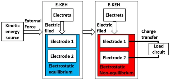
Generally speaking, the electrostatic induction effect means the charge redistribution driven by the Coulomb’s force in an isolated conductive object under an electrostatic field to get the electrostatic equilibrium state in the conductive object itself as illustrated in Figure 2- 4, while for an E-KEH, the electrostatic field is provided by an electret, the charge redistribution happens between at least two conductive electrodes connected through a load circuit, and the electrostatic equilibrium state is time-varying due to the relative movement among different components of the E-KEH under the force from an external kinetic energy source, as illustrated in Figure 2- 5.
Figure 2- 5 Schematic diagram for the basic working principle of an E-KEH.
2.3.2 Early researches
2.3.2.1 Electret transducers with variable capacitances
The basic working principle of E-KEHs was first applied to electret transducers that convert vibrations/forces into electric signals with the information of the
vibrations/forces for sensing. They usually have small dimensions, and the micro-scale relative displacements, with low-level output electric signals that need preamplifier for further signal processing. Therefore, electret transducers were usually not regarded as energy harvesters despite that they do convert kinetic energy into electricity.
It is believed that the research on electret transducers can be dated back to as early as 1929 when studies on electret microphones were going on in the United States [58]. Wax-electrets was used in electret microphones at first with drawbacks such as sensitivity fluctuations and the requirement for complex preamplifier design, then several thermoplastic electret plates and ceramic electret were suggested and attempted to be applied in electret microphones but not practically commercialized [58]. Until metalized thin electret foil made with Mylar [59, 60] and Teflon [61] were introduced into electret microphones in 1962 and 1965 by G. M. Sessler and J. E. West at Bell Laboratories, which greatly improved the performance and practicality of electret microphones, then commercialized electret foil microphones were manufactured numerously.
Figure 2- 6 Cutaway drawing of a typical foil-electret microphone (top), the photograph of a commercial foil-electret microphone (bottom left), and corresponding schematic circuit diagram (bottom right) [58].
The structure of a typical electret foil microphone is shown in Figure 2- 6. In an electret microphone, a piece of one side metalized electret foil with net homo-charges can be regarded as a constant voltage source, the sound wave vibrates a conductive backplate placed in face with the non-metalized side of the electret foil, changing the
capacitance between the backplate and the metalized side of the electret, generating output electrical signals in the external circuit connected with the backplate and the metalized side of the electret.
Besides the electret microphone, in 1976, an U.S. Patent invented by Raymond B. Basham was published, in which the possibility of utilizing Teflon electret film in a flexible force transducer to monitor the respiration of a patient was presented as shown in Figure 2- 7. Flexible steel sheets were used as electrodes. The normal breathing motion of the patient procures a varying force against the electrodes, changing the distance and consequently the capacitance between the electrode and the electret film, generating output current to the signal processing circuit.
Figure 2- 7 (a) A perspective view of the respiration monitoring apparatus positioned relative to a patient in bed with a force transducer. (b) A perspective view of the force transducer. (c) A cross-section view of an alternate embodiment of an electret force transducer. (d) An electrical schematic diagram showing a circuit with an amplifier unit for the force transducer to energize both a visual and an audible alarm to indicate cessation of respiration of the patient. Reproduced from the referenced patent [62].
Most of the later developed E-KEHs also use the variable capacitance strategy like electret transducers to generate electricity, but with more powerful kinetic energy sources, larger dimensions, and structures that can provide larger capacitance variations to get relative higher electric output.
2.3.2.2 Electret generators without variable capacitance
In addition to electret transducers using the variable capacitance strategy, in 1978, Oleg D. Jefimenko and David K. Walker [63] proposed a rotating electret generator (EG) consists of two oppositely polarized half-disks electret placed between two pairs of conducting half-disks as shown in Figure 2- 8. In this EG, the charge-transfer between the two pairs of conducting half-disks was caused by the variation of the induced charge displacement on the two pairs of electrodes during the rotation of the two oppositely charged electrets disks, not by the variation of the capacitance. As marked by the red dashed oval in Figure 2- 8(b), the left conducting half-disk on one side of the EG was electrically connected with the right conducting half-disk on the other side to form an electrode, and other two conducting half-disks were electrically connected to form the other electrode of the EG.
Figure 2- 8 (a) The photograph and (b) the exploded view of the electret generator with two oppositely charged electret plates and the half-disk structure proposed by Oleg D. Jefimenko and David K. Walker [63].
Due to its relatively large dimension (disk diameter ~152.4 mm), this EG can output power of ~0.025 W at the rotation speed of 6000 r/min and with a load resistance of 10 MΩ, and it was regarded as the first practical E-KEH by later researchers [64, 65]. In the article [63], Oleg D. Jefimenko and David K. Walker also gave theoretical calculations on the output of the EG and pointed out its characteristics of high internal impedance and facility to provide a high voltage. Later in 1981~1986, Yasufusa Tada in Japan refined and extended the theoretical model of this type of EG using segmented electrets with opposite polarizations/charges [66].
In 1992, Yasufusa Tada published an article in which he reported an EG using Teflon FEP film electret with stable homo-charges [64], and the variable capacitance strategy was employed by varying the overlap area between the stator electrode and
the rotating electret film during rotations. After that, there emerged many studies on E-KEH using the variable capacitance strategy, which will be reviewed in the following section 2.4.
2.4 Different structures of E-KEHs with variable capacitances
2.4.1 A general introduction to E-KEHs with the parallel-plate
configuration
The most common and simple structure of a capacitor is the parallel-plate configuration, which consists of dielectric materials sandwiched between two parallel-plate electrodes. For an ideal parallel parallel-plate capacitor, the capacitance ignoring the edge effect can be calculated by:
쮀 (2-7),
where C is the capacitance, S is the electrode area, and d0 is the effective dielectric
thickness between the two electrodes, as defined by the equation (2-6) but with possible different layers of dielectrics.
For E-KEHs with variable capacitances, the parallel-plate configuration is also often used, with at least one layer of electrets and usually with an air gap as dielectric layers as illustrated in Figure 2- 9.
Figure 2- 9 Illustration of the parallel-plate configuration of an E-KEH.
From equations (2-6) and (2-7), variable overlap area, variable electrode distance, and variable dielectric constant are three basic approaches to construct parallel-plate E-KEHs with variable capacitances. Some structure designs corresponding to these three approaches are shown in Figure 2- 10.
For the variable overlap area design, usually, one electrode of the E-KEH is fixed with the electret component, and the other electrode can do relative rotation, as shown in Figure 2- 10(a), or can have relative lateral displacements, as shown in
Figure 2- 10(b). Otherwise, the two electrodes can be both fixed with the electret
component, and a third conductive electrode (metal rotor) can do relative movement to change the overlap area of the third electrode with one fixed electrode in comparison with the other one, as shown in top of Figure 2- 10(c), or the two electrodes are fixed but the electret component is movable to change the overlap area of the electret with one fixed electrode in comparison with the other one, as shown in bottom of Figure 2- 10(c).
Figure 2- 10 Different types of variable capacitance E-KEHs with representative material and structure designs. (a) Relative rotation design from [64]. (b) Relative sliding design from [67]. (c) Relative sliding design from [68]. (d) Gap-varying design from [69]. (e) Gap-Gap-varying design from [70]. (f) Cellular electret design from [71]. (g) The design with movable solid dielectrics from [69]. (h) The design with movable liquid dielectrics from [72].
For the variable electrode distance design, usually at least one electrode is fixed on one side of the electret component, and the air gap between the relatively movable electrode and the fixed electrode can be changed by external motions. The gap could vary in a large range as shown in Figure 2- 10(d), but also could vary in the scale of micrometers by the deformation of flexible electret films as shown in Figure 2- 10(e). Another type of variable electrode distance design is to use cellular/foam/porous electret films that can be easily deformed, with electrodes deposited on both sides as
shown in Figure 2- 10(f). A brief introduction to cellular electret films will be particularly presented in section 2.4.2.
For the variable permittivity design, besides the electret component, there is another dielectric material that is movable between the gap of the electret and electrodes. When the movable dielectric material is driven by external motions to move, the total or partial capacitance of the E-KEH is changed. The movable dielectric material could be solid as shown in Figure 2- 10(g), or liquid as shown in
Figure 2- 10(h). Like the design in Figure 2- 10(c), the variable permittivity design
could also have both fixed electrodes. Since the electrodes of E-KEH need to output electricity to external circuit load, these designs with fixed both electrodes can greatly simplify the electric connection to external circuit load and reduce the damage risks to the electrodes and electric connectors, which is significant for developing E-KEHs with long life-times.
It is noteworthy that only several representative structure designs are presented in Figure 2- 10, and they are based on the simple parallel plate capacitor configuration. In fact, any two separated objects with any geometric shape would have a mutual capacitance between them, and their relative movement would, of course, change the capacitance value. Furthermore, even only one object can form a capacitance if regarding the environment around that object as a virtual electric ground [73]. The basic definition of capacitance is the ratio of the change in the electric charge (Q) of a system to the corresponding change in its electric potential (V), as expressed by:
쮀 (2-8).
The capacitance can be even considered as a geometrical parameter [74]. Therefore, besides the structure designs in Figure 2- 10, there are diverse other structures of E-KEH, some of them will be introduced in section 2.4.3.
2.4.2 Cellular/foam/porous piezo-electrets/ferro-electrets
In the cellular electret design represented by the research shown in Figure
2- 10(f), when the cellular electret film is pressed or released, the distance between the
two electrodes on the top and bottom sides of the electret film changes, it can also be regarded as the effective permittivity of the electret film changes, since it contains the
solid matrix (usually polymers) and the gas (usually air) in inner cavities as two different dielectrics, and when the film is deformed, the volume ratio of these two dielectrics will be changed. These cellular electret films can be charged with excess homo positive or negative charges, but are often charged with space charges (macroscopic dipole moments) on the top and bottom sides of inside cavities as illustrated in Figure 2- 11(a).
Figure 2- 11 Illustrations of (a) the analogy between the microscopic dipole moment in ferroelectrics (left) and the macroscopic dipole moment (right) in ferro-electrets, and (b) the ferroelectric-like characteristics of ferro-electrets obtained via the micro-plasma discharge inside the cavities, from [75].
When a cellular electret film charged with space charges is pressed or released, it performs like a piezoelectric material since the total macroscopic diploe moments of the electret film is changed with the deformation of the film caused by the press or elastic force, so it is called as piezo-electret [76-79]. Since the elastic modulus of the cellular electret films are usually much lower than piezoelectric ceramics, and the effective dipole moment density can be much higher than that in conventional piezoelectric materials, the apparent electromechanical d33 coefficient of
piezo-electret can be much higher than conventional piezoelectric ceramics. For instance, a tremendous d33of 3350 pC/N was obtained in a composite cellular piezo-electret film
using PTFE and PDMS [80], which is much higher than one of the best piezoelectric ceramics PZT with d33 of ~250 to 700 pC/N. The high d33 makes cellular electrets
competitive in energy harvesting. Moreover, cellular electret films can also show ferroelectric characteristics via the micro-plasma discharge inside their cavities as shown in Figure 2- 11(b), so they were also termed as ferro-electrets [75]. A recent review on cellular polymer ferro-electret and their piezoelectric properties was given by A. Mohebbi [81] for those who are interested.
2.4.3 Triboelectric nanogenerator (TENG) or tribo-electret kinetic
energy harvester (TE-KEH) with diverse structure designs
In the article corresponding to Figure 2- 10(e), authors didn’t particularly pre-charge the dielectric polymer films but took advantage of the triboelectrification effect to introduce electrostatic charges on these films, making them become tribo-electret. E-KEHs using tribo-electret were called as triboelectric generators (TEGs) [70], and later termed as triboelectric nanogenerators (TENGs) to distinguish them from traditional high voltage sources using the triboelectrification effect (such as the Wimshurst machine and the Van de Graaff generator [82, 83]). In this thesis, E-KEHs using tribo-electrets will be termed as TE-KEHs to better express their basic principle and functionality. In recent years, a large and drastically increasing number of researches on TE-KEHs were conducted [84], especially by the team of Z. L. Wang who proposed the conception of TE-KEHs [83], and pre-charged electrets were also used in several of these researches on TE-KEHs [85-90] to get higher output power.
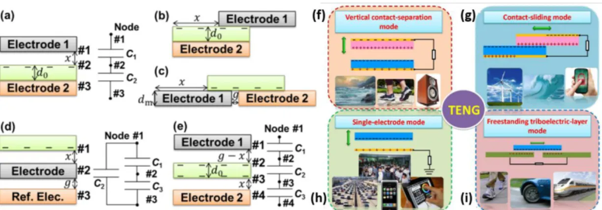
Like other E-KEHs, not only the gap-varying structure in Figure 2- 10(e) but also other types of structure designs were used in TE-KEHs for different working modes as illustrated in Figure 2- 12. Among these diverse designs, the free-standing relative sliding modes in Figure 2- 12(c) and (i), and the free-standing gap-varying modes in Figure 2- 12(e) have fixed both electrodes, and the electret is free-standing and movable.
Figure 2- 12 Basic structure designs and working modes of TE-KEHs. On the left: illustrations of TE-KEHs with (a) the gap-varying, (b) the relative sliding, (c) the freestanding relative sliding, (d) the single-electrode gap-varying, and (e) the freestanding gap-varying designs, with virtual capacitances illustrated, from [91]. On the right, illustrations of TE-KEHs working under the (f) vertical contact-separation mode, (g) in-plane sliding mode, (h) single-electrode mode, and (i)
free-standing sliding electret mode, with the external electric load and potential application scenes illustrated, from [92].
In some TE-KEHs, the electrical ground was used as one electrode, the load circuit was connected between one electrode of the TE-KEH and the electrical ground as illustrated in Figure 2- 12(h) and Figure 2- 13(a), they were regarded as single-electrode TE-KEHs [93, 94]. The electrets in TE-KEHs not only could be planar [95] [88, 93] but also could be flexible [70, 96-99], stretchable [100], and shape-adaptive [101, 102] as shown in Figure 2- 13(b) and (c), or fiber-shaped that can be woven into cloth to harvest human body motion energy [103] as shown in Figure 2- 13(d). The general shape of TE-KEHs could also be curved [104, 105] or arch-shaped [106] as shown in Figure 2- 13(e), cylindrical [107] as shown in Figure 2- 13(f), tubular [108-110] as shown in Figure 2- 13(g), polyhedral [89] or spherical [111, 112] as shown in Figure 2- 13(h). Moreover, to get more power from environmental kinetic energy sources, the integration of multiple TE-KEHs is important, which could be distributed [112-116] as shown in Figure 2- 13(i), or stacked in multi-layer [117-119] as shown in Figure 2- 13(j).
Figure 2- 13 Diverse structure and integration designs of TE-KEHs. (a) Sliding mode single-electrode structure [93]. (b) With flexible electret film for harvesting wind energy by fluttering [98]. (c) With shape-adaptive electret film [101]. (d) With electret fibers that can be woven [103]. (e) Arch-shaped TE-EKH [106]. (f) Cylindrical TE-EKH [107]. (g) Tubular TE-KEH [110]. (h) Spherical TE-KEH
[111]. (i) Distributed network integration of multiple TE-KEHs [113]. (j) Stacked integration of multiple TE-KEHs [119].
Figure 2- 14 (a) A U-tube shaped TE-KEH filled with liquid dielectrics [109]. (b) A TE-KEH with liquid metal as an electrode [120]. (c) A TE-KEH using the electret of mesoporous PDMS film impregnated with gold nanoparticles [121].
The movable liquid dielectric strategy was also used in TE-KEH [109] as shown in Figure 2- 14(a). In some other articles, liquid metals were used as the electrode that can have relative movements with the electrets in TE-KEHs, as illustrated in Figure
2- 14(b), to get a larger transferred tribo-charge amount [91, 120] for better
performance of TE-KEHs. Besides, constructing meso/micro/nano-structures on the surface of electret or electrode materials [82, 102, 107, 119, 122-125] as illustrated in
Figure 2- 13(e), (f), and (j), or cellular/porous structures [86, 121, 126, 127] inside
electret materials as illustrated in Figure 2- 14(c), are other two often-used strategies to improve the output power of TE-KEHs. A book [4] and several reviews [83, 92, 99, 114, 128, 129] on TE-KEHs were published for those who are interested.
2.4.4 Direct motion-driven mode and undirect vibration-driven mode
With different structures, E-KEHs can be driven by external kinetic sources by basically two different modes, one is the direct motion-driven mode which means the motion of the movable component of the E-KEH is directly determined by the motion
of the external kinetic source, while the other one is the undirect vibration-driven mode which means the motion of the movable component of the E-KEHs is determined by both the motion of the external kinetic source and the mechanical properties of the E-KEH itself.
Figure 2- 15 Different driven modes of E-KEHs. (a) An E-KEH with the entire structure driven by water wave motion [115]. (b) A wind-driven E-KEH with a rotating part and a stator part [130]. (c) The scheme of a KEH with a mechanical resonator structure for transferring energy from the vibration source to the electromechanical transducer [74]. (d) A micro vibration-driven E-KEH with the mechanical resonator structure, using the variable overlap area and electrode distance combined design [131]. (e) A micro vibration-driven E-KEH with the mechanical resonator structure, using the gap-varying design [132].
For the direct motion-driven mode, the external excitation force to directly drive the movable component of the E-KEH is much larger than the transduction electrostatic force, and the effect of the transduction force on the motion of the kinetic energy source is negligible. For instance, in a water wave-driven buoy-like E-KEH [115] shown in Figure 2- 15(a), external water can be part of the E-KEH as movable dielectrics (on the left), or a direct motion source to shake the E-KEH and lead to the waggle of the inner liquid dielectrics, and the electrostatic force is considered to have no effect on the water flow. This buoy-like E-KEH can be entirely placed on the sea
to harvest kinetic energy from waves. While for most of the direct motion-driven E-KEHs, there are at least two solid components with one fixed and the other one movable. For instance, in a wind-driven rotary E-KEH [130] shown in Figure
2- 15(b), there are aluminum sheets as stator electrodes and one side metalized PTFE
electret film on a rotary shaft driven by the wind as the rotor blade. A small part of the kinetic energy from wind can be converted to electricity via the wind-driven relative movement between the stator and the rotor of the E-KEH.
For vibration-driven E-KEHs that usually contain a mechanical resonator structure modeled by a spring-mass-damper system as shown in Figure 2- 15(c), the external excitation force act on the variable capacitor through the resonator structure, and the transduction force is considered to act as a damper in the resonator model. Vibration-driven E-KEHs can be entirely attached to the vibration source, and the relative movement between different parts of the electromechanical transduction unit was provided by the resonator structure excited by the vibration source. The variable capacitance design in vibration-driven E-KEHs can be a combined design of variable overlap area and variable electrode distance as shown in Figure 2- 15(d), can also be a gap-varying design as shown in Figure 2- 15(e).
The direct motion-driven mode is usually applied to E-KEHs with relatively large dimensions (from a few to tens of centimeters) for harvesting kinetic energy from low-frequency (often less 10 Hz) motions [133-135]. While the undirect vibration-driven mode is usually applied to tiny/micro E-KEHs (dimensions from a few millimeters to a few centimeters), for harvesting kinetic energy from vibrations with low to high frequency (several Hz to 1~2 kHz) [131, 136, 137] dependent on the nature frequency of the E-KEH (usually smaller E-KEHs have higher nature frequency).
2.5 Different analysis models for E-KEHs with variable capacitances
2.5.1 The compact equivalent electrical model for direct motion-driven
E-KEHs
For direct motion-driven E-KEHs, there is no need to solve the equation of motion of the movable component of the E-KEHs if the motion of the external kinetic source is given. Though there are so many different structure designs for E-KEHs as

![Figure 2- 13 Diverse structure and integration designs of TE-KEHs. (a) Sliding mode single-electrode structure [93]](https://thumb-eu.123doks.com/thumbv2/123doknet/14528707.723248/43.892.138.782.623.1008/figure-diverse-structure-integration-designs-sliding-electrode-structure.webp)
![Table 3- 1 Parameter values used in simulating the output of E-KEH for comparisons with the literature [35, 155]](https://thumb-eu.123doks.com/thumbv2/123doknet/14528707.723248/65.892.159.752.358.683/table-parameter-values-used-simulating-output-comparisons-literature.webp)