ISSN 1392 - 1207. MECHANIKA. 2013 Volume 19(4): 437-444
Numerical investigations of AC electrokinetic forces to enhance the rate
of transport of reactants in a microchannel
Abdel Aziz Khaldi*, Driss Nehari**, Mohamed Aichouni***, San Sait Eren****
*Faculty of Mechanical Engineering, University of Science and Technology of Oran Mohamed Boudiaf, Algeria, E-mail: Azizkhaldi@hotmail.com
**Laboratory of numerical modelling and experimental of mechanical phenomena, Abdelhamid Ibn Badis University, Algeria, E-mail: nehari_dr@yahoo.fr
***Mechanical Engineering Department, University of Hail, P.O. Box 2440, Hail, Saudi Arabia, E-mail: m.aichouni@uoh.edu.sa
****Institut of technology, Gebze GYTE, Istanbul, Turquie. E-mail: erens@gyte.edu.tr
http://dx.doi.org/10.5755/j01.mech.19.4.5047
Nomenclature
B - concentration of bonded molecules, molm-2; Cp - heat capacity of fluid, JKg-1 K-1; D - diffusivity of the analyte in the fluid, m2 s-1; E - electrical field, Vm-1; Koff - dissocia-tion rate constant, s-1; Kon - association rate constant, m3 mol-1 s-1; P - pressure, Pa; Q - heat source, W; R - re-action rate, molm-3 s-1; Rt - total concentration of antibody ligands, molm-2; T - temperature, K; V - electrical poten-tial, V; c - analyte concentration, molm-3; f - frequencies, Hz; k - thermal conductivity of fluid, Wm-1 K-1; u - ve-locity of fluid, ms-1; ρ - density of fluid, kgm-3; -
per-mittivity of fluid, Fm-1; η - dynamic viscosity of fluid, Kgm-1 s-1; σ - electrical conductivities of fluid, s m-1;
- charge relaxation time, s; ω - angular frequency of the
electric field, rads-1.
1. Introduction
Electrokinetic phenomena scale favourably with miniaturization and offer unique advantages in micro fluid-ics, such as low hydrodynamic dispersion, no moving parts, electrical actuation and sensing, and easy integration with microelectronics.
Electric field-based approaches are classified de-pending on the direction of the Electric charge flow that can be unidirectional or Direct current (DC) or can be reversed cyclically or alternating current (AC).
Direct current electrokinetics has a long history of development, being investigated and applied extensively [1].
However, DC electrokinetics suffers from high voltage operation (several kilovolts) and consequently excessive electrochemical reactions and electrolysis at the electrodes. In the last few years, AC electrokinetics re-ceives increasing research interest as it has demonstrated great potential for microfluidic actuation.
An AC electric field can interact with polarisable particles and fluids to set them into motion, which is known as alternating current electrokinetics ACEK [2, 3].
The effects of ACEK depend greatly in processes relating to interfacial polarization, electric double layer formation and fluid heating. As a result, three major ma-nipulative phenomena arise:
Dielectrophoresis (DEP), AC Electroosmosis (ACEO) and Electrothermal Effects (ETE) [4].
This technique has been studied in great detail for controlled manipulation of particles, binary separation and characterisation of particles [5-8]. It can be seen that die-lectrophoresis velocity is size dependent, and decreases rapidly with the distance to the electrode.
In some cases, AC electro-osmosis and AC electrothermal produce very similar flow patterns, but they are of different origin. AC electro-osmosis [9, 10] arises from the movement of ions in the electric double layer at the electrode/electrolyte interface, producing microflows because of the fluid viscosity. Pioneer work and compre-hensive review on AC electro-osmosis can be found in [2, 3, 9, 10].
So AC electro-osmosis requires both normal and tangential components of electric field at the electrode surface, which leads to the frequency dependency of AC electro-osmosis effect.
At low frequencies, most of the applied voltage drops across the double layer, AC electro-osmosis is im-portant. At high frequencies, electrode charging is negligi-ble and AC electro-osmosis becomes insignificant. Data in [9] also show that AC electro-osmosis is pronounced for frequencies lower than 100 kHz, beyond which its effect is minimal and can be neglected.
AC electro-osmosis velocity and the resulting flu-id flow exert a drag force on particles. Therefore AC elec-tro-osmosis can be used to transport particles as well as fluids, and there is no size dependency. Particle manipula-tion and fluid flow control using AC electro-osmosis have been reported in various forms, such as biased AC electro-osmosis [11, 12], and 3D AC electro-electro-osmosis pump [13, 14], travelling wave AC electro-osmosis pump [15], asymmetric electrode AC electro-osmosis pump [16] and particle traps [17-20].
However, labs-on-a-chip frequently involves samples with conductivity higher than 0.1 S/m. Biological applications regularly use saline solutions (1-2 S/m). So it is very desirable to develop an electrokinetic technique suitable for conductive fluids, and AC electrothermal ef-fect has shown promise in this aspect [21-25].
AC electrothermal arises from non-uniform elec-tric fields and temperature gradients in the fluids, which produces space charges that move under the influence of electric fields and consequently induce microflows. Higher conductivity leads to higher fluid velocity because of in-creased heat generation and temperature gradients.
Recently, AC electrothermal started to attract re-search interest again because of its increasing importance in shrinking electrokinetic chips [22]. Further miniaturisa-tion leads to higher energy density being dissipated in the fluid, and the heating source could be external or internal Joule heating [23]. A paper [24] by Gonzalez et al. has studied in great detail the AC electrothermal effect in the presence of a constant external temperature gradient.
This paper is dedicated to present numerical simu-lations and modelling of a system used to mixed a small concentration of a biological analyte with the fluid in a microchannel where a reaction surface is located on the channel walls. The flow velocity perpendicular to the sur-face is so small that the analyte, which is supposed to bind to an antibody ligand on this surface, is transported mainly by diffusion.
The rate of the binding reaction on the surface is usually large enough to bind practically all analyte mole-cules appearing there. Thus, the process is said to be transport limited and, in order to increase the reaction rate, the system must increase the transport of molecules to the reaction surface.
2. Theory
2.1. Fluid flow
Ac electrokinetic effect refers to fluid motion in-duced by temperature gradients in the fluid in the presence of AC electric fields.
When an electric field E is applied over the fluid with electrical conductivity Joule heating of the fluid will take place according to the energy balance equation:
2 1 2
0 2
k T E . (1)
For microsystems, heat convection is small com-pared to heat diffusion [2, 3]. So here the temperature equation assumes the simplified form with Joule heating as the energy source. If the field strength E is non-uniform, there will be spatial variation in heat generation, which leads to temperature gradients T in the fluid.
The electrokinetic forces are easy to control by designing optimum electrode structures and choice of field [26].
The gradient of temperature in the liquid causes inhomogeneties in the permittivity and conductivity of the medium, which give rise to forces causing fluid mo-tion. The body force can be given by [10]:
2 2 0 5 0 5 1 E E f . E . E , (2)where = / is its charge relaxation time, and = 2 f is
radian frequency. According to Green et al. [22]:
1 1 0 004. T 0 004. T t t (3) and 1 1 0 02. T 0 02. T t t . (4)
By substitution, Eq. (2) becomes:
2 2 1 0 016 0 004 2 1 2 E E E f . TE . T . (5)The force induced by a permittivity gradient is the dielectric force and the force induced by a conductivity gradient is the Coulomb force. If << / the force is dominated by the Coulomb force. If / the force is dominated by the dielectric force.
Fluid flow in the channel follows the Navier-Stokes equations: 2 E u u u u p f t . (6)
Since we are considering fluid motion in a mi-crosystem, that is, low Reynolds number, the time-averaged fluid velocity can be found by the simplified N-S equation as: 2 E u p f . (7)
Together with u = 0 for incompressible fluid,
(7) is later used in numerical simulation to obtain the fluid flow fields in the present AC electrokinetic model.
2.2. The electric field
Because the electrothermal force is a time-averaged entity, it is sufficient to solve the static electric field that corresponds to the root mean square (rms) value of the AC field.
To solve the electrostatics problem, turn to La-place’s equation can be used [27]:
2 0 V , (8) with E V (9)
and the constitutive equation
D E. (10)
2.3. Heat transfer
The generation of the amount of Joule heating in a very small volume could give rise to a temperature in-crease in the fluid. In order to estimate the temperature rise for a given electrode array, the energy balance equation must be solved [28]: 2 p p T C C u T k T Q t . (11)
The power that a unit volume of fluid absorbs through Joule heating is:
2
E
The heat source, Q, appears in the stationary heat balance equation:
k T
Q C u Tp , (13)
where Cp denotes the heat capacity.
2.4. Convection and diffusion of the analyte
The material balance of the analyte comes from the equation:
c D c R u c t , (14)where D denotes the diffusion coefficient and R represents the reaction rate. Here R equals zero because no reactions take place in the bulk of the fluid, only on the reaction surface.
The reaction surface contains a total concentration
Rt of antibody ligands. The portion of the bonded
mole-cules is the concentration B. The binding rate depends on the analyte concentration on the surface, c, on the concen-tration of free antibodies, and on the association rate con-stant kon. Similarly, bonded antibodies dissociate with a rate that depends on the concentration of the bonded lig-ands and on the dissociation rate constant koff. Therefore, the reaction between immobilized ligand and analyte can be assumed to follow the first order Langmuir adsorption model [29, 30] is:
on t off B k c R B k B t . (15)The reaction rate of the analyte on the surface equals the negative of the binding rate on the surface.
The model assumes that the antibodies do not dif-fuse on the surface and that there is no leakage of the mol-ecules at the edges of the surface.
3. Results
3.1. First configuration
For the purpose of comparison of the numerical model, the latter was used to predict the flow configuration reported in a recent study by Wu et al. [31]. In this config-uration, which is shown in Fig. 1, an AC electric field is applied to induce Joule heating in microchannel. The in-duced electrothermal force will generate a vortex field which can lead to a reduction to the thickness of the diffu-sion layer and hence accelerates the reacting rate and shorten the experimental time.
Parameters such as amplitude of the voltage, the gap between electrodes and the width of electrodes will be varied and the subsequent flow structure will be computed for the same conditions reported by Wu et al. The contribu-tion of our work will be the investigacontribu-tion of the effect of the height of microcantilver and length of the reaction surface on the overall performance of the microchannel. These two effects have not been studies in previous stud-ies.
Fig. 1 General view of 2-D model
The numerical mesh used for the simulations is shown in Fig. 2 where the number of elements is 23586.
Fig. 2 General view the mesh of the 2-D model 3.1.1. Effect of the width electrodes
The comparison of our numerical results with those reported in [31] shows a good agreement as present-ed in Fig. 3. This would indicate that the numerical model developed in the present study is suitable for the purpose of this study.
Fig. 3 Concentration of the bonded molecules, (Present results and Ming-Chih Wu results)
3.1.2. Effect of the gap between electrodes
Here again, good agreement was obtained by our present results and early results [31] as shown in Fig. 4.
Fig. 4 Concentration of the bonded molecules, (Present results and Ming-Chih Wu results)
3.1.3. Effect of the voltage amplitude
The results represented in Fig. 5 show that the number of adsorbed molecules on the surface increases more rapidly when the voltage of the electrical field is higher than 10 V and for a voltage less than 10 V no change can be noticed.
Fig. 5 Concentration of the bonded molecules (in different voltages)
Fig. 6 Concentration of the bonded molecules (in different voltages)
Fig. 7 Distribution of temperature field with voltage of 25 V
Fig. 6 shows good agreement between the predic-tions of the present model and those obtained by Wu et al. [31] for different voltages. It shows also that increasing the intensity of the voltage positively affect the binding of
molecules on the surface reaction in the microchannel. This effect was found to be associated with an increase in the temperature field as shown in Figs. 7 and 8. These findings are similar to results obtained by [31].
Fig. 7 represents the distribution of temperature field computed at the voltage of 25 V. It can be seen that at this voltage, there was an increase in the temperature field to a maximum value of 8 Kelvin.
The comparison between our results and those re-ported by Wu et al. [31] shown in Fig. 8 shows an accepta-ble agreement. However, the slight differences noticed specifically in Fig. 8 can be attributed the size of the mi-crochannel geometry in [31] was not mentioned.
Fig. 8 Difference in temperature as a function of voltage, (Present results and Ming-Chih Wu results)
3.1.4. Effect of the position of reaction surface
The effect of the position of the microcantiliver (surface reaction) within the microchannel was investigat-ed. As a new contribution of the present study, the micro-cantiliver was place at a distance H from the electrodes, and then this distance was reduced to ¾ H, ½ H and ¼ H. For each distance flow structure was simulated.
The numerical results which are represented in Fig. 9 show that the height of the surface reaction plays an important role on the concentration of the bonded mole-cules. The figure shows that as the distance between the electrodes and the surface reaction decreases, there was an increase in the concentration. This is mainly due to flow and thermal field interaction and the effect of the micro-channel geometry on the thermofluids structures.
Fig. 9 Bonded molecules Concentration (different position of the surface reaction)
3.1.5. Effect of the width of reaction surface
In order to investigate the effect of the width of surface reaction itself, we set the amplitude of voltage to 25 V, the width of electrodes is 60 µm and the gap to 15 micrometers, and we vary the width of reaction surface of 40, 60 µm and 80 µm.
The results presented in Fig. 10 show that the width of reaction surface has an opposite effect for the binding of molecules on the reaction surface in the micro-channel. It can be seen neatly from the figure when the width of the reaction surface increases there is a decrease in the concentration.
Fig. 10 Concentration of the bonded molecules (in differ-ent widths of reaction surface)
3.2. Second configuration
The second part of the paper will deal with the flow configuration presented in Fig. 11. The reaction sur-face is on the lower wall of the microchannel itself; the two electrodes are located on the upper boundary at same dis-tances of centre of channel. A fluid flows from left to right in the channel. The incoming flow profile is a fully devel-oped laminar flow that is parabolic with zero velocity at the channel walls. An applied electrothermal force creates swirling patterns in the flow at the channel’s centre.
Fig. 11 Geometry for the second model of microchannel The two electrodes produce an AC electric field that heats the fluid and creates the electrothermal force. We assume that the electrodes are perfect heat conductors and remain at a constant ambient temperature. At the inlet and the outlet, the temperature gradually approaches the ambi-ent. At all other boundaries the model assumes that the
channel is thermally and electrically insulated.
The incoming flow has a small concentration of a biological analyte, which the reaction surface on the upper boundary transports and adsorbs. Any remaining concen-tration exits the channel with the fluid at the right bounda-ry.
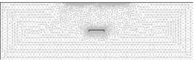
Fig. 12 shows the mesh we used for the analysis and it consists of 19963 elements.
Fig. 12 The mesh of the microchannel 3.2.1. Influence of the amplitude of voltage
In this second part of the study, the channel ge-ometry was set as: the gap between the electrodes set at 20 µm, the length of the surface reaction 80 µm and the width of the electrode at 60 µm; Then an electrical field was applied with different voltage respectively: 0, 5, 10, 15, 20, and 25 V and numerical simulations were obtained.
Fig. 13 shows the flow profile and concentration distribution without any applied electric field. In this case, the flow is laminar and has a parabolic profile. The effect of the reaction surface on the analyte concentration is visi-ble only in the narrow region near the surface.
As shown from the simulations presented in Fig. 14 when an electrical voltage is applied between the electrodes the flow profile becomes far from parabolic: it has two distinct swirls and a narrow region with high flow velocity between the electrodes. Both the flow structure and the concentration field become totally different due to the electrical field applied.
Fig. 15 shows the number of adsorbed molecules (the ratio between the total amount and the surface width) on the surface for different electrical voltages (0-25 V). It can be seen that increasing the intensity of the voltage affects positively the binding of molecules on the reaction surface in the microchannel especially after a period rang-ing from 100 to 450 s of releasrang-ing the biologically analyte.
Fig. 13 Microchannel flow and concentration at 100 s without any applied electric field
Fig. 14 Microchannel flow and concentration at 100 s with an applied electric field at the voltage of 25 V
Fig. 15 Concentration of the bonded molecules (in different voltages)
3.2.2. Effect of the width of electrodes
To investigate the effect of the electrodes width, the gap between the electrodes was set at 20 µm and the length of the surface reaction 40 µm then we change the width of the electrode as 60, 65 and 70 µm for the simula-tion.
Fig. 16 shows that the width of the electrodes does not affect the concentration of binding of molecules on the reaction surface in the microchannel.
Fig. 16 Concentration of the bonded molecules (in differ-ent widths of electrodes)
3.2.3. Effect of the electrodes gap
Fig. 17 shows the effect of different gaps between the electrodes, we consider the distance of the gap as 10, 20 and 30 µm.
It can be seen that the distance of the gap between electrodes affects positively the concentration of binding of molecules on the reaction surface in the microchannel. The gap of 20 µm was chosen as the optimal parameter.
Fig. 17 Concentration of the bonded molecules (in differ-ent gap between the electrodes)
3.2.4. Effect of the width of reaction surface
To study this effect computation were obtained for three values of the width of the reaction surface as 40, 60 and 80 µm. Fig. 18 shows that the width of reaction surface has an opposite effect for the binding of molecules on the reaction surface in the microchannel. As shown before in Fig. 16, change of electrodes width does not affects the flow structure and the concentration.
Fig. 18 Concentration of the bonded molecules (in differ-ent width of reaction surface)
4. Conclusions
In this study, we have used the AC electrokinetic forces to enhance the Rate of transport of reactants to a reaction surface.
The study in this paper is divided into two parts. In the first part we have rebuilt the model of [31] and we changed many parameters namely: the length of electrodes,
the length of space between two electrodes, the voltage of electric current and the length of the reaction surface to see their influence on results, than we compare our results with the results of [31].
Then our own contribution in this model that has not been studied in [31] is the change of the height of mi-crocantilver and the width of reaction surface to see their influence on results.
In conclusion we find that our results are entirely consistent with the results of [31] with a slight difference that can be explained by the size of the microchannel ge-ometry used in both studies that are not detailed in [31].
We can say if we change the height of the micro-cantilver, the concentration of the bonded molecules ex-change with a proportional manner and the width of reac-tion surface have an effect inversely proporreac-tional to the results.
In the second part we simulate a different model in which the reaction surface is on the wall of microchan-nel itself, and we vary the same parameters as in the first case.
In the second study we found almost the same re-sults when we change all the initial parameters, except that if we change the width of surface reaction, because if we Increased the reaction surface at 80 µm and we various the width of electrodes we will have differences in the results.
The change in the width of reaction surface was found to affect the computed flow structure in the micro-channel and the reaction rate. Increasing the length of reaction surface has a negative effect on the attachment of molecules on the surface reaction and changing the width of electrodes or the gap between electrodes don’t changes the concentration of the bonded molecules like the first case.
Acknowledgements
This research was supported by the Laboratory of Experimental and numerical modelling of mechanical phenomena of the University of Abdelhamid Ibn Badis Mostaganem, Algeria in cooperation with the group NANOFLU (Microfluidics and Nanostructures for chemis-try and biology) of the Laboratory Photonics and Nanostructures (LPN / CNRS), Paris, France.
References
1. Li, D. 2004. Electrokinetics in Microfluidics, Elsevier Academic Press.
2. Ramos, A.; Morgan, H.; Green, N.G.; Castellanos,
A. 1998. Ac electrokinetics: a review of forces in
mi-croelectrode structures, J. Phys. D: Appl. Phys. 31: 2338-2353.
http://dx.doi.org/10.1088/0022-3727/31/18/021. 3. Castellanos, A.; Ramos, A.; Gonzalez, A.; Green,
N.G.; Morgan, H. 2003. Electrohydrodynamics and
dielectrophoresis in microsystems: scaling laws, J. Phys. D: Appl. Phys 36: 2584-2597.
http://dx.doi.org/10.1088/0022-3727/36/20/023. 4. Pohl, H.A. 1978. Dielectrophoresis, Cambridge
Uni-versity Press, Cambridge.
5. Pethig, R. 1991. Application of A. C. electrical fields to the manipulation and characterisation of cells in Karube, I. (Ed.): Automation in biotechnology,
Else-vier, 159-185.
6. Gascoyne, P.R.C.; Vykoukal, J.V. 2004. Dielectro-phoresis-based sample handling in general-purpose programmable diagnostic instruments, Proc IEEE, 92: 22-42.
http://dx.doi.org/10.1109/JPROC.2003.820535. 7. Morgan, H.; Hughes, M.P.; Green, N.G. 1999.
Sepa-ration of submicron bioparticles by dielectrophoresis, Biophysical J. 77: 516-525.
http://dx.doi.org/10.1016/S0006-3495(99)76908-0. 8. Ramos, A.; Morgan, H.; Green, N.G.; Castellanos,
A. 1999. The role of electrohydrodynamic forces in the
dielectrophoretic manipulation and separation of parti-cles, J. Electrostatics 47: 71-81.
http://dx.doi.org/10.1016/S0304-3886(99)00031-5. 9. Green, N.G.; Ramos, A.; Gonzalez, A.; Morgan, H.;
Castellanos, A. 2000. Fluid flow induced by
nonuni-form ac electric fields in electrolytes on microelec-trodes, I. Experrimental mesurements, Phys Rev, 61: 4011-4018.
http://dx.doi.org/10.1103/PhysRevE.61.4011.
10. Green, N.G.; Ramos, A.; Gonzalez, A.; Morgan, H.;
Castellanos, A. 2002. Fluid flow induced by
nonuni-form ac electric fields in electrolytes on microelec-trodes. III. Observation of streamlines and numerical simulation, Phys. Rev. E 66: 026305.
http://dx.doi.org/10.1103/PhysRevE.66.026305. 11. Wu, J. 2006. Biased AC electro-osmosis for on-chip
bioparticle processing, IEEE Trans. Nanotech. 5(2): 84-89.
http://dx.doi.org/10.1109/TNANO.2006.869645. 12. Lian, M.; Islam, N.; Wu, J. 2006. Particle line
assem-bly/patterning by microfluidic AC electroosmosis, J. Phys, Conf. Series 34: 589-594.
http://dx.doi.org/10.1088/1742-6596/34/1/097.
13. Bazant, M.Z.; Ben, Y. 2006. Theoretical prediction of fast 3D AC electro-osmotic pumps, Lab Chip, 6: 1455-1461.
http://dx.doi.org./10.1039/b608092h.
14. Urbanski, J.P.; Thorsen, T.; Levitan, J.A.; Bazant,
M.Z. 2006. Fast AC electro-osmotic micropumps with
non-planar electrodes, Appl. Phys. Lett. 89: 143508. http://dx.doi.org./10.1063/1.2358823.
15. Ramos, A.; Morgan, H.; Green, N.G.; Gonzalez, A.;
Castellanos, A. 2005. Pumping of liquids with
travel-ing-wave electroosmosis, J. Appl. Phys. 97: 084906. http://dx.doi.org./10.1063/1.1873034.
16. Studer, V.; Pepin, A.; Chen, Y.; Ajdari, A. 2004. An integrated AC electrokinetic pump in a microfluidic loop for fast tunable flow control, Analyst 129: 944-949.
http://dx.doi.org./10.1039/B408382M.
17. Wu, J.; Islam, N.; Lian, M. 2006. High sensitivity particle detection by biased ac electro-osmotic trapping on cantilever, 19th IEEE Int. Conf. Micro Electro Me-chanical Systems (MEMS 2006), Istanbul, Turkey, 566-569.
18. Wong, P.K.; Chen, C.Y.; Wang, T.F.; Ho, C.M. 2003. An AC electroosmotic processor for biomole-cules, TRANSDUCERS 03, 20-23.
19. Hoettges, K.F.; McDonnel, M.B.; Hughes, M.P. 2003. Use of combined dielectrophoretic/ electrohy-drodynamic forces for biosensor enhancement, J. Phys. D: Appl. Phys. 36: L101-L104.
http://dx.doi.org/10.1088/0022-3727/36/20/L01. 20. Wu, J.; Ben, Y.; Battigelli, D.; Chang, H.C. 2005.
Long-range AC electrokinetic trapping and detection of bioparticles, Indust. Eng. Chem. Res. 44(8): 2815-2822.
http://dx.doi.org/10.1021/ie049417u.
21. Fuhr, G.; Schnelle, T.; Wagner, B. 1994. Traveling wave-driven microfabricated electrohydrodynamic pumps for liquids, J. Micromech. Microeng. 4: 217-226.
http://dx.doi.org/10.1088/0960-1317/4/4/007.
22. Green, N.G.; Ramos, A.; Gonzalez, A.; Castellanos,
A.; Morgan, H. 2001. Electrothermally induced fluid
flow on microelectrodes, J. Electrostat. 53: 71-87. http://dx.doi.org./10.1016/S0304-3886(01)00132-2. 23. Green, N.G.; Ramos, A.; Gonzalez, A.; Castellanos,
A.; Morgan, H. 2000. Electric field induced fluid flow
on microelectrodes: the effect of illumination, J. Phys. D: Appl. Phys. 33: L13–L17.
http://dx.doi.org/10.1088/0022-3727/33/2/102.
24. Gonzalez, A.; Ramos, A.; Morgan, H.; Green, N.G.;
Castellanos, A. 2006. Electrothermal flows generated
by alternating and rotating electric fields in Microsys-tems, J. Fluid Mech. 564: 415-433.
http://dx.doi.org/10.1017/S0022112006001595. 25. Sigurdson, M.; Wang, D.Z.; Meinhart, C.D. 2005.
Electrothermal stirring for heterogeneous immunoas-says, Lab Chip 5: 1366-1373.
http://dx.doi.org/10.1039/B508224B.
26. Morgan, H.; Sun, T. 2010. AC electrokinetic particle manipulation in Microsystems, Microfluidics based mi-crosystems for security-fundamentals and applications, Springer.
27. Strattom, J.A. 1941. Electromagnetic Theory, McGraw Hill, New York, 615 p.
28. Landau, L.D.; Lifshitz, E.M. 1959. Fluid Mechanics, Pergamon, Oxford, 536 p.
29. Brynn Hibbert, D.; Justin Gooding, J. 2002. Kinetics of irreversible adsorption with diffusion: Application to biomolecule immobilization, Langmuir 18: 1770-1776. http://dx.doi.org/10.1021/LA015567N.
30. Langmuir, I. 1918. The adsorption of gases on plane surfaces of glass, mica and platinum, J. Am. Chem. Soc. 40: 1361-1403.
http://dx.doi.org/10.1021/JA02242A004.
31. Wu, M.C.; Chang, J.S.; Yang, K.C. 2007. 2-D Anal-ysis of Enhancement of Analytes Adsorption Due to Flow Stirring by Electrothermal Force in The Micro-cantilever Sensor, EDA Puplishing/DTIP.
A. Khaldi, D. Nehari, M. Aichouni, S. S. Eren
KINTAMOSIOS SROVĖS ELEKTROKINETINIŲ JĖGŲ SKAITMENINIS TYRIMAS SIEKIANT PADIDINTI REAGENTO GREITĮ MIKROKANALE
R e z i u m ė
Straipsnyje pateikiami kintamosios srovės elekt-rokinetinio reiškinio mikroskysčiuose tyrimo rezultatai. Jie rodo, kad elektrodų pločio ir tarpo tarp jų kitimas neturi įtakos rezultatams, bet, jei pakeičiamas mikrogembės aukš-tis, susietųjų molekulių koncentracija pakinta proporcingai, o reakcijos paviršiaus pločio įtaka yra atvirkščiai propor-cinga rezultatams. Tyrimai taip pat rodo, kad reakcijos paviršiaus ilgio didinimas turi neigiamą įtaką molekulių prisijungimui prie reaguojančio paviršiaus, o elektrodų pločio arba tarpo tarp jų keitimas turi įtakos susietųjų mo-lekulių koncentracijai. Pateikti skaitmeniniai rezultatai gali būti laikomi įnašu į mikrokanalų, naudojamų lusto labora-toriniuose tyrimuose, konstrukciją.
A. Khaldi, D. Nehari, M. Aichouni, S.S. Eren
NUMERICAL INVESTIGATIONS OF AC ELECTRO-KINETIC FORCES TO ENHANCE THE RATE OF TRANSPORT OF REACTANTS IN A MICROCHAN-NEL
S u m m a r y
The present paper presents an investigation to study of AC electrokinetic phenomena in microfluidics.
The results show that the variation of the width of electrodes and the gap between electrodes has no effect on the results, but if we change the height of the microcantil-ver, the concentration of the bonded molecules exchanged with a proportional manner and the width of reaction sur-face has an effect inversely proportional to the results. The results show also that increasing the length of reaction surface has a negative effect on the attachment of mole-cules on the surface reaction and changing the width of electrodes or the gap between electrodes changes the con-centration of the bonded molecules.
The present numerical results can be considered as a contribution to the design of the microchannel used in lab-on-a-chip applications.
Keywords: microfluidic, electrokinetic force, electrode
electrothermal force, electroosmosis, lab-on-a-chip, sur-face of reaction, simulation, biological analyte.
Received March 15, 2012 Accepted June 17, 2013