A MODEL FOR PREDICTING THE ELECTRICAL RESISTIVITY OF BAKED ANODES Dipankar Bhattacharyay1, Duygu Kocaefe1, Yasar Kocaefe1, Brigitte Morais2, Marc Gagnon2
1Centre universitaire de recherche sur l’aluminium (CURAL), University of Quebec at Chicoutimi, 555 Boulevard de l'Université, Chicoutimi, QC, G7H 2B1, Canada
2Aluminerie Alouette Inc.; 400, Chemin de la Pointe-Noire, Sept-Îles, QC, G4R 5M9, Canada Keywords: Electrical resistivity, Anode, Artificial neural network
Abstract
Carbon anodes are one of the key components of primary aluminum production. One of the desired properties of the anodes is low electrical resistivity. A proper understanding of the effect of different parameters on electrical resistivity can help produce better quality anodes. A model has been developed to predict the anode electrical resistivity. First, using the Kopelman model for the thermal conductivity of a composite material, the specific electrical resistivity was modeled for the solid part (coke/cokified pitch) assuming coke as the dispersed phase in the cokified pitch matrix. Then, the effects of the anode porosity, distribution of particles, and coke properties are incorporated into the model using an approach based on the work of Shimizu. A factor which is a function of particle size and other properties is introduced. This factor was estimated using the artificial neural network. Published data were used to validate the model.
Introduction
More than half of the electrical energy input is dissipated as heat due to the electrical resistivity of various components in an electrolytic cell. The best technology uses 50% of the energy for aluminum production. Great effort is being spent to reduce these resistivities to decrease the energy consumption. Carbon anodes are an essential part of the aluminum electrolysis process. Reduction of the electrical resistivities through anodes and its components helps lower the energy dissipated as heat. Thus, losses from different parts of anode assemblies have attracted the attention of many researchers.
Some researchers have modeled the electrical losses in stub-anode connectors. Molenaar [1], Kandev and Fortin [2] applied a simplified thermo-electrical 3D finite element model to investigate the electrical losses in stub-anode connectors. Peterson [3] studied the variation in stub-cast iron resistance and temperature distribution in anodic connectors. Brooks and Bullough [4] investigated the variation in resistivity at stub-cast iron contact as a function of cast iron thickness.
Andersen and Zhang [5] developed a 2D finite element model for energy consumption of an anode immersed in an electrolytic cell and studied the effect of geometry and anode-cathode distance. Adams et al. [6] showed that the resistivity of anodes depends on the pitch percentage.
Chollier-Brym et al. [7] developed an equipment to measure the electrical resistivity of industrial anodes. In the article, they highlighted that carbon material itself is responsible for about 50% of the total voltage drop in the anode assembly. Depending on the variation of raw materials, forming and baking conditions, anode resistivities vary significantly between batches.
In spite of the significant contribution of carbon materials in anode resistivities, little work has been published to predict the resistivities of anodes. The focus of the present work is to develop a simple model which will take into account various process parameters and the properties of baked anode.
In this model, an anode is treated as a composite material of calcined coke and cokified pitch. There are various models for the electrical resistivity of composite materials.
Mclachlan [8] explained the electrical conductivities of composite materials in terms of percolation and Bruggeman’s effective media theories. They also accounted for the shapes of the particles, namely, spherical and ellipsoidal.
Ruschau et al. [9] presented the resistivity of conducting composites as a combination of a number of resistors connected in series and parallel. They considered the filler resistance as well as the constriction and tunneling resistances at the contacts of different particles.
Sevkat [10] applied statistical tools such as the Weibull distribution to predict the resistivity of a polymer-carbon fiber matrix. A statistical tool was employed to predict the cleavage of the fibers under stress.
Chen and Chung [11] studied the effect of conducting carbon fibers and nonconducting silica fillers in a nonconducting matrix of cement on the electrical resistivity of composites.
Merzouki [12] applied the Mamunya model in explaining the electrical resistivity of a polypropylene matrix filled with carbon black and acetylene black. The model was in good agreement with the experimental results when the fillers were present above the percolation threshold.
Zhang and Wi [13] used Monte Carlo simulation to predict the effect of the distribution of short conducting fibers in a polymer matrix on the electrical resistivity.
The literature review on the modeling of electrical resistivity of composites revealed that they dealt mainly with systems comprising of a conducting phase distributed in a non-conducting phase.
The system of carbon anodes is different from those composites because it consists of conducting coke particles distributed in a conducting cokified pitch matrix. Thus, this work deals with conducting materials distributed in a conducting matrix. It also takes into account the porosity of the anode.
Model
The model has been developed in two parts. The first part deals with the prediction of the specific resistivity of anodes, without any pore, containing coke dispersed in a cokified pitch matrix. Kopelman model [14] for the measurement of the thermal conductivity of a composite material has been used for the prediction of specific electrical resistivity.
The second part deals with parameters like anode porosity, particle size distribution, hardness of coke and green anode density. This part has been handled in light of the work of Shimizu [15].
Kopelman model [14] is used to determine the thermal conductivity of a composite material. This model is applied for the estimation of the equivalent thermal conductivity of samples having a continuous and a dispersed phase. It is often used in food industries to measure the thermal conductivity of food items such as tortilla chips and French fries.
According to the Kopelman model, the equivalent thermal conductivity for a composite with particles dispersed in a continuous matrix is given as:
]
1
[
1
]
1
[
3 / 1 f mX
Q
Q
k
k
−
−
−
=
(1) where
−
=
m f fk
k
X
Q
2/31
(2)k
: equivalent thermal conductivitym
k
:thermal conductivity of the continuous phase (pitch)f
k
:thermal conductivity of the dispersed phase (coke)f
X
:volume fraction of the dispersed phaseTo develop a model for predicting the specific electrical resistance of anodes, the Kopelman model has been utilized by replacing the thermal conductivity terms by the specific electrical conductance. In this model, cokified pitch has been assumed as the continuous phase and the calcined coke particles as the dispersed phase. When pitch is cokified during baking, the conductivity of pitch approaches to that of conducting graphitic carbon (specific electrical resistivity = 35 µΩm) [16]. The average specific electrical resistivity of calcined coke (with pores) is of the order of 500 µΩm. The objective of the model is to show that it is possible to have an equivalent specific electrical resistivity of around 50 µΩm in the presence of around 85% calcined coke. Thus, replacing the thermal conductivity terms by the corresponding specific electrical conductance terms and taking the specific electrical resistivity (ρ: specific electrical resistivity of only coke-pitch system in the absence of pores, ρm: specific electrical resistivity of pitch as the continuous phase, ρf: specific electrical resistivity of coke as the dispersed phase) as the reciprocal of the specific electrical conductivity, the equations (1) and (2) can be modified as follows:
] 1 [ 1 ] 1 [ 1 1 3 / 1 f m X Q Q − − − =
ρ
ρ
(3) where
−
=
m f fX
Q
ρ
ρ
1
1
1
3 / 2 (4) The volume fraction of coke particles (without porosity) dispersed in the cokified pitch matrix of the anode has been calculated as follows. If BAD represents the baked anode density of anode, then the volume per unit mass of baked anode is 1/BAD. If φ is the porosity of the anode, then the volume of the anode without porosity (volume of the solid part) per unit mass of baked anode is (1- φ)/BAD. If Wm is the weight fraction of pitch, then the weight fraction of coke becomes 1- Wm. If df is the real density of the coke, then the volume of coke per unit mass of baked anode (without pores) is (1- Wm)/df.Thus, the volume fraction of coke (without pores) in the anode can be obtained by dividing the volume of coke (without pores) by the volume of anode (without pores):
BAD
d
W
X
f m f/
)
1
(
/
)
1
(
ϕ
−
−
=
(5) whereϕ
:porosity of anode (= 1- BAD/BRAD) BRAD : real density of baked anode Suffix m denotes pitch and f denotes coke.The real density of the baked anode was assumed to be 0.02 g/cm3 higher than the real density of coke [17].
As the coke is a porous medium and the effective electrical resistivity of coke is measured including the effect of pores, ρf (which is specific electrical resistivity of coke without pores) needs to be determined. ρf has been calculated based on the treatment of Meredith and Tobias [18]. Assuming that the electrical resistance of air in the pores is parallel to that of the carbon of coke, then:
a f c f
ρ
ρ
ψ
ψ
ρ
ρ
)
1
(
−
+
=
(6) or a c fρ
ψ
ρ
ψ
ρ
1
)
1
(
1
−
−
=
(7) where cψ
: porosity of cokea
ρ
:electrical resistivity of air = 1.3 x 10²² µΩmFollowing the approach proposed by Shimizu [15], the effects of parameters such as, particle size, hardness of coke, and green anode density are included through a correlation factor τ. The effect of anode porosity, φ, is also included in the calculation of the effective specific electrical resistivity, ρeff:, of baked anode as shown below:
ϕ
ρτ
ρ
−
=
1
eff (8) whereτ
: a correlation factor effρ
: effective specific electrical resistivity of baked anode As ρ stands for resistivity of anode without porosity, the effect of anode porosity has been considered by dividing it by 1-φ. As a rule of thumb, if φ increases ρeffshould also increase. Here as φ increases, 1-φ decreases, thus value of ρeff increases (Equation 8). In the model, the effective specific electrical resistivity is determined using Equation 8. ρ is found using Equations 3, 5, and 7. The value ofτ
is calculated based on the feed-forward artificial neural network with back-propagation.Methodology
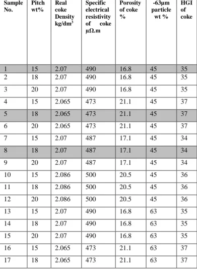
The ANN approach requires data for training the model. Part of the data published in the thesis of Chmelar [19] was used to train the ANN for τ, and the rest to validate the model. The researcher used four different types of coke and one pitch and mixed them in different proportions. He also varied the particle size of the coke and measured a number of properties of the anode. To study the effect of coke particle size, he mixed in the feed different percentages of coke having a particle size of -63 µm.
Table 1 shows the different formulations for anodes and the corresponding properties of the raw materials. Table 2 shows the properties of the anode for each formulation. Using the values in Table 1, ρf, Xf and Q were calculated using Equations (7), (5) and (4), respectively. Then ρ values for all the samples were
calculated using equation (3).
From Equation (8) τ can be expressed as
ρ
ϕ
ρ
τ
=
eff(
1
−
)
(9)
The values of τ were calculated for all the samples assuming
eff
ρ
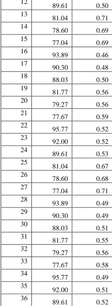
as the measured electrical resistivity of the anode samples using Equation (9).Table 3 shows the calculated values of ρ and τ for all the samples from the data of Chmelar [19].
A multi-layered custom feed-forward artificial neural network model with back propagation was developed to predict the values
of
τ
as the dependent parameter using the values of the HGI (Hardgrove Grindability Index) of coke and green anode apparent density and percentage of dust in the raw material as independent parameters. The network contained one input layer, two hidden layers and one output layer. The transfer functions associated with the hidden layers 1 and 2 were log-sigmoid and linear respectively. The network was trained using Levenberg-Marquardt back-propagation algorithm available in Matlab 7.9. During training, the results of the samples 1, 5, and 8 (Table 1, gray rows) were not included; they were used only for the validation of the model. The trained network was finally used to predict the values ofτ
corresponding to samples 1, 5, and 8. The predicted values ofτ
were used to calculate the effective electrical resistivity of the anodes using Equation (8).Results and discussion
The model was used to predict the specific electrical resistivity data of the baked anodes. Table 3 shows the calculated values of ρ and τ for the anode samples from the data of Chmelar [19]. It can be seen that the factor τ varied within the range of 0.46 to 0.71 for the data analyzed. This variation in τ can be attributed to the properties of coke such as the particle distribution and HGI. As it can be seen from Equation 8, if the value of
τ
is small, the resistivity is small.Table 1. Properties of raw materials for anode samples (the shaded values were used for the prediction of resistivity)
Sample No. Pitch wt% Real coke Density kg/dm3 Specific electrical resistivity of coke µΩ.m Porosity of coke % -63µm particle wt % HGI of coke 1 15 2.07 490 16.8 45 35 2 18 2.07 490 16.8 45 35 3 20 2.07 490 16.8 45 35 4 15 2.065 473 21.1 45 37 5 18 2.065 473 21.1 45 37 6 20 2.065 473 21.1 45 37 7 15 2.07 487 17.1 45 34 8 18 2.07 487 17.1 45 34 9 20 2.07 487 17.1 45 34 10 15 2.086 500 20.5 45 36 11 18 2.086 500 20.5 45 36 12 20 2.086 500 20.5 45 36 13 15 2.07 490 16.8 63 35 14 18 2.07 490 16.8 63 35 15 20 2.07 490 16.8 63 35 16 15 2.065 473 21.1 63 37 17 18 2.065 473 21.1 63 37
18 20 2.065 473 21.1 63 37 19 15 2.07 487 17.1 63 34 20 18 2.07 487 17.1 63 34 21 20 2.07 487 17.1 63 34 22 15 2.086 500 20.5 63 36 23 18 2.086 500 20.5 63 36 24 20 2.086 500 20.5 63 36 25 15 2.07 490 16.8 94 35 26 18 2.07 490 16.8 94 35 27 20 2.07 490 16.8 94 35 28 15 2.065 473 21.1 94 37 29 18 2.065 473 21.1 94 37 30 20 2.065 473 21.1 94 37 31 15 2.07 487 17.1 94 34 32 18 2.07 487 17.1 94 34 33 20 2.07 487 17.1 94 34 34 15 2.086 500 20.5 94 36 35 18 2.086 500 20.5 94 36 36 20 2.086 500 20.5 94 36
Table 2. Properties of anode samples (the shaded values were used for the prediction of resistivity)
Sample No. Specific electrical resistivity of baked anode µΩ.m Green anode density, kg/dm3 Baked anode density, kg/dm3 1 77.3375 1.514 1.45 2 72.56 1.562 1.47 3 72.9 1.554 1.43 4 66.8 1.424 1.35 5 65.325 1.463 1.36 6 65.9 1.449 1.33 7 69.5 1.47 1.39 8 66.67 1.521 1.43 9 67.5 1.489 1.41 10 79.5 1.44 1.38 11 67.9 1.5 1.41 12 68.9 1.483 1.38 13 86.175 1.515 1.395 14 76.66 1.583 1.489 15 76.85 1.576 1.45 16 65.28 1.418 1.374 17 64.5 1.485 1.4 18 66 1.471 1.378 19 69.1 1.5 1.39 20 65.7 1.571 1.42 21 68.5 1.544 1.395 22 73.8 1.498 1.42 23 66.9 1.585 1.5 24 68 1.589 1.481 25 79.5 1.515 1.429 26 74.9 1.583 1.493 27 77.6 1.576 1.47 28 71.8 1.418 1.345 29 67.5 1.485 1.378 30 68.4 1.471 1.356 31 66.66 1.5 1.41 32 64.78 1.571 1.44 33 65.8 1.544 1.42 34 70.5 1.498 1.405 35 65.4 1.585 1.499 36 66.4 1.589 1.475
Table 3. Calculated values of ρ and τ from the data of Chmelar [19] Sample No.
ρ
µΩ.mτ
1 81.04 0.66 2 78.60 0.65 3 77.04 0.65 4 93.89 0.46 5 90.30 0.47 6 88.03 0.48 7 81.77 0.57 8 79.27 0.58 9 77.67 0.59 10 95.77 0.54 11 92.00 0.4912 89.61 0.50 13 81.04 0.71 14 78.60 0.69 15 77.04 0.69 16 93.89 0.46 17 90.30 0.48 18 88.03 0.50 19 81.77 0.56 20 79.27 0.56 21 77.67 0.59 22 95.77 0.52 23 92.00 0.52 24 89.61 0.53 25 81.04 0.67 26 78.60 0.68 27 77.04 0.71 28 93.89 0.49 29 90.30 0.49 30 88.03 0.51 31 81.77 0.55 32 79.27 0.56 33 77.67 0.58 34 95.77 0.49 35 92.00 0.51 36 89.61 0.52
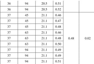
An effort was made to analyze the influence of some parameters on the value of
τ
. The effects of HGI, porosity of coke and percent of -63 µm particles on the value of τ are summarized in Table 4. It shows that, for similar values of HGI and porosity of coke,τ
does not change significantly with the variation in percentage of the -63 µm particles (see standard deviations of only 0.01, 0.02, 0.02 and 0.02 in Table 4). Thus the percentage of -63 µm particles does not have a significant contribution to the value of τ and in turn to resistivity of anode. The combination of HGI and porosity of coke have a significant influence on the values ofτ
. It was observed that for small values of HGI (34) and a medium value of porosity (17.1) of coke, the values ofτ
(average 0.57) were small. Then with increase in HGI (35), the value ofτ
increased significantly (average 0.68). With further increase in HGI (36 and 37) and porosity (20.5 and 21.1), the values ofτ
decreased significantly (average 0.51 and 0.48 respectively). Thus the hardness and porosity of coke together are important controlling factors for the resistivity of anodes. The model can help find the optimum HGI and porosity of coke to produce anodes with lower electrical resistivity.The resistivities of samples 1, 5, and 8 were calculated using the predicted values of
τ
. Table 5 shows that the predictions are in good agreement with the experimental values with a percent average absolute error of 1.65.Conclusions
The model presents a simplified approach to predict the electrical resistivity of anodes. The deviation from theoretical value has been handled using a correlation factor
τ
which can significantly control the resistivity of anodes. Other parameters remaining the same, a smaller value ofτ
indicates a smaller value of resistivity. Properties of coke such as HGI and porosity significantly govern the value ofτ
and in turn the resistivity of anode. The use of neural network to predict the value ofτ
has been a key factor in predicting the electrical resistivity. For better predictions, more data are required to train the network. Thus with a large quantity of industrial data, this technique can play a significant role in the quality control of anodes.Table 4. Study of the effect of different parameters on τ
HGI of coke -63µm particle % Porosity, % τ Average τ Standard deviation of τ 34 45 17.1 0.57 0.57 0.01 34 45 17.1 0.58 34 45 17.1 0.59 34 63 17.1 0.56 34 63 17.1 0.56 34 63 17.1 0.59 34 94 17.1 0.55 34 94 17.1 0.56 34 94 17.1 0.58 35 45 16.8 0.66 0.68 0.02 35 45 16.8 0.65 35 45 16.8 0.65 35 63 16.8 0.71 35 63 16.8 0.69 35 63 16.8 0.69 35 94 16.8 0.67 35 94 16.8 0.68 35 94 16.8 0.71 36 45 20.5 0.54 0.51 0.02 36 45 20.5 0.49 36 45 20.5 0.50 36 63 20.5 0.52 36 63 20.5 0.52 36 63 20.5 0.53 36 94 20.5 0.49
36 94 20.5 0.51 36 94 20.5 0.52 37 45 21.1 0.46 0.48 0.02 37 45 21.1 0.47 37 45 21.1 0.48 37 63 21.1 0.46 37 63 21.1 0.48 37 63 21.1 0.50 37 94 21.1 0.49 37 94 21.1 0.49 37 94 21.1 0.51
Table 5. Predicted values Sample
No
Calculated
τ
Predictedτ
Measured value of resistivity µΩ.m Predicted value of resistivity µΩ.m 1 0.66 0.69 77.3375 80.32 5 0.47 0.47 65.325 65.37 8 0.58 0.57 66.67 65.99 AcknowledgementsThe technical and financial support of Aluminerie Alouette Inc. as well as the financial support of the National Science and Engineering Research Council of Canada (NSERC), Développement économique Sept-Îles, the University of Québec at Chicoutimi (UQAC), and the Foundation of the University of Québec at Chicoutimi (FUQAC) are greatly appreciated.
References
1. D. Molenaar, K. Ding, A. Kapoor, “Development of Industrial Benchmark Finite Element Analysis Model to Study Energy Efficient Electrical Connections for Primary Aluminium Smelters”, Light Metals,( 2011), 985-990.
2. N. Kandev, H. Fortin, “Electrical Losses in the Stub-Anode Connection: Computer Modeling and Laboratory Characterization”, Light Metals, (2009), 1061-1066.
3. R.W. Peterson, “Studies of stub to carbon voltage”, Light Metals, (1978), 367-.378.
4. D.G. Brooks, V.L. Bullough, “Factors in the Design of Reduction Cell Anodes”, Light Metals, (1984), 961-976.
5. D. H. Andersen, Z. L. Zhang, “Carbon Anode Modeling for Energy Savings in the Aluminium Reduction Cell”, Light Metals, (2011), 1009-1014.
6. A. N. Adams, J. P. Mathews, H. H. Schobert, “The Use of Image Analysis for the Optimization of Pre-baked Anode Formulation”, Light Metals, (2002), 545-552.
7. M. J. Chollier-Brym, D. Laroche, A. Alexandre, M. Landry, C. Simard, L. Simard, D. Ringuette, “New Method for Representative Measurementof Anode Electrical Resistance”, ”, Light Metals, (2012), 1299-1302.
8.D.S. McLachlan, M. Blaszkiewicz, R.E. Newnham, “Electrical Resistivity of Composites”, J. Am. Ceram. Soc.,73(8) (1990), 2187-2203.
9.G. F.L. Fiuschau, S. Yoshikawa, R. E. Newnham, “Resistivities of Conductive Composites”, J. Appl. Phys., 72 (3) (1992), 953-959.
10. E. Sevkat, J. Li, B. Liaw, F. Delale, “A Statistical Model of Electrical Resistance of Carbon Fiber Reinforced Composites under Tensile Loading”, Composites Science and Technology, 68 (2008), 214-2219.
11.P.W. Chen, D.D.L. Chung, “Improving the Electrical Conductivity of Composites Comprised of Short Conducting Fibers in a Nonconducting matrix: The Addition of a Nonconducting Particulate Filler”, Journal of Electronic Materials, 24(1) (1995), 47-51.
12. A. Merzouki, N. Haddaoui, “Electrical Conductivity Modeling of Polypropylene Composites Filled with Carbon Black and Acetylene Black”, ISRN Polymer Science, (2012), 1-7.
13. T. Zhang, Y.B. Yi, “Monte Carlo Simulations of Effective Electrical Conductivity in Short-Fiber Composites”, J. Applied Physics, 103 (014910) (2008), 1-7.
14. S. Sahin, S.G. Sumnu, “Physical Properties of Food”, Springer, (2008).
15. S. Shimizu, T. Yamaguchi, Y. Fujishiro, M. Awano, “Effect of Microstructures on the Conductivity of porous (La0.8Sr0.2)0.99MnO3”, Journal of the Ceramic Society of Japan, 117(8) (2009) 895-898.
16. J. Xue, J. Zhu, Y. Song, “Electrical Resistance of Graphitic and Graphitized Cathode Materials at Elevated Temperatures”, Light Metals, (2010), 829-834.
17. D.Sulaiman, R. Garg, “Use of Undercalcined Coke to Produce Baked Anodes for Aluminium Reduction Lines”, Light Metals, (2012), 1147-1151.
18. M. Kandula, “The Effective Thermal Conductivity of Porous Packed Beds with Uniform Spherical Particles”, Journal of Porous Media, 14 (10) (2011), 919-926.
19. J. Chmelar, “Size Reduction and Specification of Granular Petrol Coke with Respect to Chemical and Physical Properties”, (PhD Thesis, Norwegian University of Science and Technology, 1992).
![Table 3. Calculated values of ρ and τ from the data of Chmelar [19] Sample No](https://thumb-eu.123doks.com/thumbv2/123doknet/7672281.240359/4.918.476.696.742.1061/table-calculated-values-ρ-τ-data-chmelar-sample.webp)