HAL Id: hal-02066598
https://hal.archives-ouvertes.fr/hal-02066598
Submitted on 13 Mar 2019
HAL is a multi-disciplinary open access
archive for the deposit and dissemination of
sci-entific research documents, whether they are
pub-lished or not. The documents may come from
teaching and research institutions in France or
abroad, or from public or private research centers.
L’archive ouverte pluridisciplinaire HAL, est
destinée au dépôt et à la diffusion de documents
scientifiques de niveau recherche, publiés ou non,
émanant des établissements d’enseignement et de
recherche français ou étrangers, des laboratoires
publics ou privés.
Evolution of defects in Ti6-4 under Ti2+ ion irradiation:
Focus on radiation-induced precipitates
Sylvie Doriot, Emilie Jouanny, Joël Malaplate, France Dalle, Lucien Allais,
Thierry Millot, Marion Descoins, Dominique Mangelinck, Moukrane Dehmas
To cite this version:
Sylvie Doriot, Emilie Jouanny, Joël Malaplate, France Dalle, Lucien Allais, et al.. Evolution of defects
in Ti6-4 under Ti2+ ion irradiation: Focus on radiation-induced precipitates. Journal of Nuclear
Materials, Elsevier, 2018, 511, pp.264-276. �10.1016/j.jnucmat.2018.09.027�. �hal-02066598�
OATAO is an open access repository that collects the work of Toulouse
researchers and makes it freely available over the web where possible
Any correspondence concerning this service should be sent
to the repository administrator:
[email protected]
This is an author’s version published in:
http://oatao.univ-toulouse.fr/23193
To cite this version:
Doriot, Sylvie and Jouanny, Emilie and Malaplate, Joël and Dalle, France and
Allais, Lucien and Millot, Thierry and Descoins, Marion and Mangelinck,
Dominique and Dehmas, Moukrane
Evolution of defects in Ti6-4 under Ti2+
ion irradiation: Focus on radiation-induced precipitates. (2018) Journal of
Nuclear Materials, 511. 264-276. ISSN 0022-3115
Evolution of defects in Ti6-4 under ri
2+ion irradiation: Focus on
radiation-induced precipitates
Sylvie Doriot
a,*,Emilie Jouanny
a, b, c,Joël Malaplate
a,France Dalle
a,Lucien Allais
a,Thierry Millot
c,Marion Descoins
d,Dominique Mangelinck
d,Moukrane Dehmas
b, 1a DEN-Service de Recherches Métallurgiques Appliquées, CEA, Université Paris-Saclay, F-91191, Gif-sur-Yvette, France
b Institut Jean Lamour, UMR 7198 CNRS-Université de Lorraine, Campus ARTEM, 2 Allée André Guinier, BP 50840, 54011, Nancy Cedex, France
c Naval Croup Research, Centre Grand Nantes -Techno Campus Océan, 5 Rue de L'Halbrane, 44340, Bouguenais, France d JM2NP, CNRS, Aix Marseille Université, Case 142, Faculté de Saint Jérôme, 13397, Marseille Cedex 20, France
HIGHLIGHTS
• Irradiation-induced precipitates were observed after ion irradiation for both irradiation temperatures at 300 °C and 430 °C. • A probable mechanism for the distribution of vanadium-rich � precipitates is the heterogeneous nucleation.
• The nucleation of precipitates is dominated by the Radiation Induced Segregation (RIS) phenomenon at 430 °C.
• The influence of rising the irradiation temperature from 300 °C to 430 °C appears very modest for <a>-type loops in Ti6-4.
ARTICLE INFO ABSTRACT
Keywards:
Titanium alloy Irradiation defects Dislocation loops Precipitates
Transmission electron microscopy Charged particle irradiation
Ion irradiations on the Ti6-4 titanium alloy were conducted at the JANNUS French platform in two different conditions of temperatures, doses and fluxes, to simulate neutron irradiation damage. Quan tification of defects and chemical microanalyses were carried out thanks to Transmission Electron Mi croscopy and Atom Probe Tomography. <a>-type loops and radiation induced precipitates (a vanadium rich � BCC phase) were observed for both irradiation temperatures. During an irradiation at 300 °C, there was no notable influence of the dose and flux for the considered doses and fluxes ranges on the <a>-type defects. The influence of raising the irradiation temperature up to 430 ° C was a lowering of their density and an increase of their mean diameter for both defects. In addition, a lower flux seemed to enhance this temperature effect. These phenomena were very significant for precipitates whereas it appeared very modest for <a>-type Ioops. The probable mechanism to explain the distribution of vanadium-rich � precipitates inside the [/. phase is the heterogeneous nucleation. The nucleation is dominated by the Radiation Induced Segregation (RIS) phenomenon at 430 °C and couid be dominated by the mechanism of vanadium-rich clusters formation by ballistic effects in the cascades at 300 °C.
1. Introduction
In the nuclear field, a good mechanical strength under
• Corresponding author.
E-mail addresses: [email protected] (S. Doriot), [email protected] (E. Jouanny), [email protected] Q. Malaplate), [email protected] {F. Dalle), [email protected] {L. Allais), [email protected] (T. Millot), marion. [email protected] (M. Descoins), [email protected] {D. Mangelinck), [email protected] {M. Dehmas).
1 Present address: CIRIMAT, Université de Toulouse, 4 allée Emile Monso, BP 44362, Toulouse Cedex 04, 31030, France.
https://doi.org/10.1016/j.jnucmat.2018.09.027
irradiation and a good corrosion resistance are required for mate rials used as components operating in the core of Pressurized Water Reactors. Currently, the 304L stainless steel is widely used for in ternai structures in the core of these reactors but its applications have often been constrained due to the activation and mass of the material. Thus, it would be interesting to use a material which al lows a significant decrease in activation and mass with similar mechanical strength and corrosion resistance. The objective is to facilitate maintenance operations, dismantling and recycling facil ities. In this way, titanium and its alloys are good candidates as potential nuclear structure materials [ 1 ]. Chemical elements within titanium alloys are far more favorable from activation point ofview
than ones of 304 steel. Indeed, in the framework of the ANR TESAMI project, activation calculations have been performed for both ma terials for the same core feature. The results shew, on one hand, that 99.9% of the activity for 304 and Ti6-4 were due to respectively Co60 and Sc46 and, on the other hand, that after 100 h after reactor shut down, the ratio between the 304 activity and Ti6-4 one was about 125. After 20 years this ratio raised to 380. For reactor exploitation and decommissioning, it is obvious that the use of ti tanium alloys could be of the greatest importance. Furthermore, for shipped reactor, gain weight (304 density is twice higher than that of the titanium alloys) can also argue for the titanium use. For this reason, the study of the microstructural evolution of the titanium alloys under irradiation is of great interest.
Unlike r:,. Ti alloys [2], the tensile behavior of ( r:,.+B) Ti6-4 alloy is known to evolve noticeably after neutron irradiation, not only at low irradiation temperature (::;250 °C) [3,4], but also at higher
irradiation temperature near 350 °C [ 5 ]. The irradiation at low
temperature induced the occurrence of small numerous irradiation defects (dislocation loops, black dots) in both r:,. and (r:,.+B) alloys [6]. Therefore, a moderate increase in the yield stress as well as in the ultimate tensile strength with a decrease in the total and uniform elongations was observed in both r:,. and (r:,.+B) Ti6-4 alloys in these low irradiation temperature conditions at the dose of 0.3 dpa. The Ti6-4 alloy seemed to be more affected than the r:,. alloy. The irra
diation at 350 °C caused a very substantial amount of hardening in
the (r:,.+B) Ti6-4 alloy and a decrease in the total and uniform elongations, while the mechanical strength of the r:,. titanium alloys
was not strongly affected [6]. The hardening observed in the (r:,.+B)
Ti6-4 alloy at 350 °C appeared to be related in this alloy to the
radiation-induced precipitation that occurred at doses as low as 0.3
dpa [7]. From the literature, these precipitates were platelet-shaped
vanadium-rich B particles and followed the well-known Burgers crystallographic relation with the r:,. matrix [8]. This relation induces the occurrence of six equivalent precipitate crystallographic ori entations or variants [9].
(Oll)r,//(0001),, and [111]//[1120],,
High energy proton irradiations were carried out at similar dose and temperature ranges to those of low dose neutron irradiations: similar influences of irradiation in microstructural features and in
tensile properties were obtained [10]. Very few experiments with
heavy ions (vanadium, aluminum, nickel or copper) are available in the literature. It was nevertheless mentioned that after heavy ion
irradiations (1.5-32 dpa) at temperatures ranging from 450 °C to
700 °C, vanadium-rich B precipitates were observed into the r:,.
phase of Ti6-4 alloy. After irradiation at 700 °C, the presence of
precipitates was not detected and dislocations seemed to pre dominate in the material [9,11-13 ]. Table 1 collects irradiation conditions for neutron, proton and heavy ion experiments on Ti6-4 alloy from the literature, and main features of the microstructure observed in each case. Considering the ion irradiations, it appears
from Table 1 that the radiation-induced precipitates were resolved
on the micrographs only from the irradiation temperature of 450 °C. Quantitative measures (length, number density, chemical composition) were in short supply and carried out from the irra
diation temperature of 500 °C. At these irradiation conditions the
radiation-induced precipitates measured more than 50 nm in length and the <a>-loop contrast had almost disappeared. As seen in Table 1 these microstructures were not representative of the microstructures observed after neutron irradiation in a reactor
(250°C-350 °C) with smaller precipitates and tangled contrasts of
<a>-type loops and precipitates.
The ion irradiations avoids long and expensive irradiations in
nuclear reactors, leading to radio-active samples that are thus not easy to prepare and analyze. However, the dose-rates and the in teractions between the particles and the material are known to be very different in the case of neutron or ion irradiations [15]. Therefore the aim of this study is to reproduce with heavy ion ir radiations what happens with neutrons (dislocation loops, pre cipitation) and to complete the few data available about heavy ion irradiations in the literature on Ti6-4 alloy with temperatures representative of irradiation temperatures in a reactor.
The nature, size and density of radiation-induced defects are likely to be important parameters governing the in-reactor behavior of the material. Consequently, for a better understand ing of mechanical behavior taking account of the characteristics of the irradiation-induced defects, it appeared necessary to identify and quantify these defects after irradiation. This consideration prompted the present study that was focused on the effects of ion irradiation parameters (temperature, dose and flux) on the pres ence, size, density and nature of radiation-induced defects, in the Ti6-4 alloy. In particular, it seemed necessary to confirm the pres ence of vanadium-rich B precipitation after ion irradiation at low temperature. Quantification of defects in the r:,. phase was carried out thanks to image analysis of TEM (Transmission Electron Mi croscopy) micrographs and thanks to APT (Atom Probe Tomogra phy) analyses. The mechanisms of defects appearance were also discussed.
2. Material and experimental procedures
The considered material is a Ti6-4 (grade 5) alloy. This material was provided by TIMET Savoie, France, as a bar of 100 mm in diameter. The nominal chemical composition (in wt.%) of the as
received material is given in Table 2. The determination of substi
tutional solute elements was carried out by Inductively Coupled Plasma (!CP) analysis. Combustion and infrared absorption mea surement, fusion hot extraction, reducing molten in a nickel bath and infrared absorption were used for the determination of C, 0, N elements respectively.
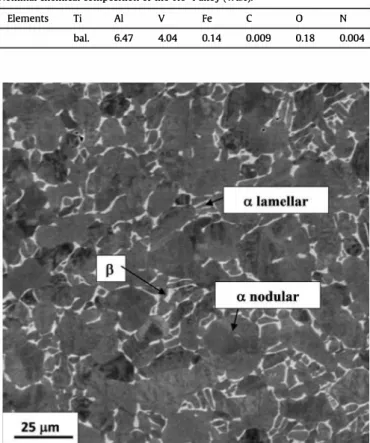
After hot forming in the (r:,. + B)2 domain, Ti6-4 alloy was
annealed for 2 h at 730 °C and subsequently air cooled. Conse
quently, a duplex microstructure was observed as shown in Fig. 1.
This microstructure consists of both some nodular and some lamellar r:,. phase (in grey) surrounded by some B phase (in white). The nodular particles have a mean equivalent diameter of about 10 µm. The apparent size of the r:,. lamellar phase is about several micrometers in thickness and 10 µm in length. The cooling rate after the annealing was low (several bars were cooled together), thus no r:,.' phase was expected. The r:,. lamellar phase came from the precipitation of some r:,. phase in the B grains during the cooling. The surface fraction of the B phase was measured before irradiation by
BSE-SEM micrographs as seen on Fig. 1 and was about 10%.
Disk specimens with a diameter of 3 mm and a thickness of
100 µm were irradiated using Ti2+ ions with an energy of 6 MeV at
the JANNUS French platform in a similar way as described in Ref. [16]. The simulation of the damage profile using SRIM (the
Stopping and Range of Ions in Matter) software is given on Fig. 2
(Kinchin Pease mode, displacement threshold energy Ed = 25 eV,
a fluence of 1016 atoms/cm2). The damage took place only at the
surface of the sample, up to 2 µm deep.
Thanks to a specific preparation method, a thin foi! located up to about 200 nm from the irradiated surface was observed by TEM. For irradiation and further TEM observations, the disk specimens were first machined from the as-received state. Then, the samples were
Table 1
Irradiation conditions for neutron, proton and heavy ion microstructural experiments on Ti6-4 alloy from the literature, and main features of the microstructure observed in each case.
Incident particles Dose Tirr ("C) defects Length x width (nm) Number density (m-3) Ref. Dose-rate
neutrons 0.3 dpa 50 High density of small defects [6,7]
3.5 x 10-s dpa ç1 350 Coarse loops and platelets 40 X 5
protons 0.3 dpa 350 A dense dislocation forest and a fine precipitation >15 [10]
3 x 10⁻⁶ dpa ç1
Al3+ 2 dpa 500 Precipitates dominate the microstructure 65 1.2 X 10¹⁵ [11]
9MeV 550 87 2.0 X 10¹⁵
600 140 5.3 X 10¹⁴
650 400 6.0 X 10¹²
700 No irradiation defects
Cu4+ 1.5 dpa 250 Dense tangle of precipitates and loops (no details can be resolved) [14]
17.5MeV 3 x 10⁻⁴ dpa ç1 350 Similar to 250 "C but coarser (damages too dense to resolve precipitates and loops) 450 The precipitates dominate the microstructure (Burgers relation)
v+ 3-25 dpa 450-550-650 Precipitation of P platelets with Burgers relation No influence of the dose [9] 2 .4MeV
Table 2
Nominal chemical composition of the Ti6-4 alloy (wt.%).
Elements Ti Al V Fe C 0 N
bal. 6.47 4.04 0.14 0.009 0.18 0.004
Fig. 1. BSE-SEM micrograph of the as-received Ti6-4 titanium alloy ( the rJ. and P phases appear in grey and white, respectively).
prepared by electropolishing (twin jet electrolytic thinning) to reduce the thickness until Jess than 50 µm, before subjecting them to the irradiation. Only one face was polished at this step. To do that, two disks were put together back to back and the resulting samples have one face polished and the second one unpolished. The irradiation was carried out on the polished face. After irradiation, the disk was thinned again to obtain a hole at the center of the disk by electropolishing on the non-irradiated face only (backpolishing). The irradiated face was protected using Lacomit vamish. No surface layer of the irradiated face has been removed. An electrolyte con taining 10% perchloric acid and 90% ethanol, at -10 °C and 30 V was
14 12
10
TE oôse,va ons 4 �
2 •
Rises with Tirr 90 x 18 at 650"C ■ ■ • � 3.SE-03 ri' ••• ·---➔
.
.
,
#' • • •_.
:r
.·
,,.,,.
.
.
..
.. .
.
....
•
•
••
•
.
.
•
l.OE•Ol 3,,
2.Sf-03 ;;-2.0Hllg
·
:, LSl:-03i
,:, 3 LO!·Ol -5.0!·02 �..J ... ...,co,uc!,•�•�••---•!__��--+--+-+-+-->--+---+'lilll____ O.Of-000.0 0.5 LO 1.5
Implantation depth (µm)
2.0 2.5
Fig. 2. Damage and ion implantation profiles determined from SRIM simulation for irradiations carried out with Ti2+ ions at an energy of 6 MeV, using an aluminum foil
degrader (0.8 µm thick) in front of the specimens (3 dpa 430 'C high flux). The part of the profile concerned by TEM observations is indicated.
used [16]. As radiation induced defect structures were suspected to
be affected by surface effects, a cross sectional sample was also prepared using Focused Ion Bearn (FIB) technique (3 dpa 430 °C) to check this point. It appeared thanks to the FIB thin foi! that the irradiated depth was consistent with what was predicted by SRIM calculation and, in addition, no difference was observed in the radiation-induced microstructure between the first 200 nm and the deeper irradiated areas ( quantitative measurements were carried
out). The observed area was far from the implanted zone (Fig. 2),
thus no impact of the implanted self-interstitial atoms was ex pected on the observed defect structures. 19 samples can be fully
irradiated at the same time during one irradiation [16]. The irra
diation was performed in a triple beam chamber using the 2 MV Tandem Pelletron JAPE'J'I'M of the JANNUS facility [17,18]. The sam
ple temperature was measured by a K-type thermocouple welded on the sample surface. The beam current measurements were performed every 10 min with a movable device of multi-Faraday cups (going up and down). Both temperature and ion beam offered a good stability during irradiation. The lowest and highest temperatures measured during each irradiation are given in
Table 3.
Irradiations at two different doses (0.6 and 3 dpa) were carried out. For both doses, a high flux (7 x 10¹¹ ions.cm-2,ç1, 2 x 10⁻⁴ dpa/s) was chosen. Moreover, for the lower dose 0.6 dpa, a second lower flux (3.5 x 10¹⁰ ions.cm-2.ç1, 8 x 10⁻⁵ dpa/s) was also
Table 3
Measured doses, dose-rates and temperatures of the ion irradiations in the present study. Comparison with the theoretical temperature from eq. ( 1 ), emulating with ion irradiation the neutron irradiation microstructure at 350 °C (T eq neutron 350°c) [6,7]
and 250 °C (Teq neutron 2so0c) [2].
Dose (dpa) Dose-rate (dpa ç1) Tirr (°C) Teq neutron 350"'C Teq neutron 250°C
3 2.32 X 10⁻⁴ 410-430 425 288 0.6 1.95 X 10⁻⁴ 410-430 423 287 0.6 8.62 X 10⁻⁶ 410-430 395 269 3 2.15 X 10⁻⁴ 300-310 424 288 0.6 1.55 X 10⁻⁴ 270-280 421 286 0.6 7.46 X 10⁻⁶ 270-280 393 268 Table4
Linear dislocation density in as received state and after heat treatment Ti6-4 alloy. As received
6 h 45O°C
Linear dislocation density (m per m-3) (3.4 ± 1.7) x1013
(4.0 ± 2.4) x1013
considered. Thanks to the high damage-rate, only one or two days are required to reach the expected irradiation doses. The temper ature for ion irradiation should be chosen to produce irradiation
damage in materials relevant to nuclear reactor cores. Mansur [19]
and Was et al. [15] proposed a formula to determine the shift in
temperature to compensate for the damage-rate difference when ion beam irradiation is used for simulating neutron irradiation.
(
kT�)1n(K2)
� K;"
(__.!ili_) ln(&)
E,,,n+2Evt K1(1) where T1 is the actual temperature in nuclear reactor, T2 is the designed temperature for ion irradiation, K1 and K2 are the dose rates of neutron and ions irradiations, k is the Boltzmann con
stant, Evm is the migration energy of vacancy and Evr is the vacancy
formation energy. This formula can be applied if the net flux of vacancies over interstitials to a particular type of sinks is invariant and if the temperature shift derived in this way is for the recombination-dominated regime. The present irradiations were carried out at rather low temperatures and high fluxes, and thus probably were in the domain were the formula applies. Based on the given values of Evm = 0.50 eV [20], Evr= 1.96 eV [20],
k = 8.617 x 10⁻⁵ eV/K, the two targeted temperatures for ion irra diation (300 ac and 450 aq were chosen in order to reproduce what happens during neutron irradiation at low (::;250 ac) and medium
(350 aq temperatures, respectively [6,7]. Table 3 gives the
measured values of dose, dose-rate and temperature, during the present ion irradiations. The theoretical temperature can be calculated from Equation (1 ), to emulate with ions the neutron
irradiation microstructure observed at 350 ac (Teq neutron 350°c) by
Tahtinen et al. [6,7] 3 and at 250 ac (Teq neutron 250°c) by Kozhenikov et al. [2].4 It appears first in Table 3 that the experimental irradia tion temperatures are very close to the targeted values. Then, for an experimental value of 430 ac (resp. 300 ac), Teq neutron 35O°c (resp.
Teq-neutron 2so0c) is very close to the experimental value, especially with the high dose-rate. It means that the observed microstructure in this study at 430 ac (resp. 300 ac) is expected to be similar to the observed microstructure in the literature after neutron irradiations in the high (resp. low) temperature domain (about 350 ac (resp.
3 dose-rate 3.5 x 10-s dpa/s.
4 the dose-rate of the research reactor is assumed to be about 3 x 10⁻⁷ dpa ç1•
Table 5
Number density and mean diameter of <a>-type loops in Ti6-4 alloy after irradiation at 300 °C and 430 °C.
Irradiation condition 3 dpa 300 °C high flux 0.6 dpa 300 °C high flux
0.6 dpa 300 °C Iow flux
3 dpa 430 °C high flux
0.6 dpa 430 °C high flux
0.6 dpa 430 °C low flux
250 ac)). Number density (m-3) 2.4 ± 1.6 X 10²² 2.3 ± 0.3 X 10²² 1.7 ± 1.1 X 10²² 1.0 ± 0.3 X 10²² 1.0 ± 0.3 X 10²² 0.6 ± 0.2 X 10²² Mean diameter (nm) 7±2 7±2 7±2 8±2 9±3 10±2
The irradiated samples were then observed by TEM in order to characterize the <a>-type dislocations and loops and the radiation induced precipitates. The TEM examinations were conducted using a 200 kV Jeol 2100 microscope. These examinations were focused on the microstructural evolution under irradiation. For <a>-type
loop imaging, a
g
= 1 OÎ 1 diffracting vector was used near the zoneaxis B = [1210] or B = [1123]. In this imaging conditions, only 2/3 of
loops respected the g.b
*
0 condition and were visible on the micrographs. Consequently, the number density is given by taking into account a corrective factor of 3/2 to compensate for these missing loops. For precipitate imaging, observations were con
ducted near a zone axis B = [1123]c,;. These zone axis are numerous
(there are 6 of them) and are easily recognizable. In this orientation conditions two of the six variants (named Vl and V2 in the following) predicted by the Burgers relation are close to the zone axis B = [11Î]p orientation and one of the {011}p plans of ail the other variants is close to the Bragg position (this is indicated by stereographic projections). Thus ail the precipitates are in contrast and in addition appear in the micrographs near an edge-on posi tion. Then observations were carried out at a slight angle from the rJ. matrix zone axis in order to position one of the two variants Vl or
V2 (Vl for instance) in B = [11Î]p or in
g
= 011p orientation. Thus,the matrix appeared out of contrast ( <a>-loop contrast became much weaker), allowing a better visualization of the precipitates. In these observation conditions ail the variants could usually be observed but Vl precipitates appeared more numerous and with a better contrast than the others. Precipitate distributions were counted on bright field pictures with a magnification of 60 k. Only the Vl variant was taken into account for the counting. Therefore
the TEM precipitate densities indicated in Table 8 was multiplied by
6 from the counting results.
The defect distributions were counted by image analysis, using
the Noesis Visilog software™. After choosing an area on the
micrograph, defects were selected and defined manually with a graphie tablet and thus automatically counted and measured as
explained elsewhere [16]. It can be noticed that the influence of
truncation by foi! surface can be neglected for <a>-type loops and precipitates. The quantitative analyses of the defects were carried out in several a nodules and lamellae in order to increase the counting statistics. As results conceming independent a nodules and lamellae were similar, following results will represent a phase in general (nodules + lamellae). For each condition, the counting was carried out on several hundred of defects. The thin foi! thick ness of the considered location was measured by EELS (Electron Energy Loss Spectroscopy). This technique considers energy dis tribution of electrons, which have crossed the sample. The thicker the sample, the bigger the incident electron energy Joss. Severa! authors have established the link between the t/À parameter and the ratio of plasmon peak area and zero Joss peak in the energy Joss distribution, where t is the thickness of the analyzed zone and À the mean free path for inelastic scattering [21-24 ].
Table 6
Mean length and number density of the radiation-induced precipitates determined by APT analyses after irradiation with high flux in Ti6-4 alloy. Precipitate mean length (nm)
Precipitate number density (1023 m-3)
Table 7
430°C-3 dpa 10.2 ± 5.3 1.8 ± 0.2
Chemical composition of non-irradiated a (APT analyses) and p (EPMA analyses) phase; a phase and precipitates in Ti6-4 irradiated at 3 dpa and 0.6 dpa at 430 °C and 3 dpa at 300 °C: weight % of vanadium, aluminum and iron (APT analyses). The balance to 100 wt% corresponds to Ti.
Weight % V Al Fe
a phase - non-irradiated 2.7 ±0,1 6.7 ± 0.2 0.02 ±0,01 Native P phase - non-irradiated 17.6±0.8 2.8 ± 0.1 1.4 ± 0.1 a phase - 430°C-3 dpa 1.1 ±0.2 6.9 ± 0.38 0.04±0.01 P precipitate - 430 °C-3 dpa 50 ± 8.3 4.2± 1.0 0.06±0,1 a phase - 430 °C-0.6 dpa 0.9±0,03 7.0 ± 0.33 0.04±0,01 P precipitate - 430 °C-0.6 dpa 50±8.0 4.3 ±0.09 0.09±0.16 a phase - 300°C-3 dpa 1.6±0.2 6.9 ± 0.3 0.04±0.01 P precipitate - 300 °C-3 dpa 45±9 4,7±1.3 0.04±0,16 Table 8 430°C-0.6 dpa 10.7 ±8,0 1.3 ± 0.15 300°C-3 dpa 5.6± 1.9 10.1 ± 1.3
in width. In these sub-grains, small arrays of short dislocations were observed. There were <a>-type dislocations heterogeneously dispersed. These sub-grains were already observed in the literature [25-27], and notably by Leguey in a Ti6-4 alloy produced by TIMET in a similar way.
A heat treatment at 450 °C during the same time (6 h) as for the irradiation at high flux up to 3 dpa was carried out to evaluate the effect of temperature without irradiation. The microstructure of this annealed state was similar to that of the as-received state. The dislocation density, measured by the intercept method, was similar in both cases and is reported in Table 4. This means that an annealing at 450 °C for 6 h induced no significant recovery of the dislocations. An annealing at 430 °C (the same temperature as the
Precipitate number density, mean length and mean width ofTi6-4 irradiated at 430 °C high flux at the dose of 0.6 and 3 dpa and low flux at the dose of 0.6 dpa determined from TEM observations.
3 dpa High flux 0.6 dpa High flux 0.6 dpa Low flux
Number density (1022 m-3) 6,8±1.8
5.6 ± 1.7 1.4 ± 0.7
(APT) analyses were carried out in order to obtain chemical and morphological information about the precipitates. Needle tips were prepared by the focused ion beam (FIB) lift-out technique: sections of dimensions 10 x 2 x 2 µm were extracted from the samples in a FEI Helios Nanolab 650 dual beam FIB machine at CEA, and pieces of sections (2 x 2 x 2 µm) were mounted onto fiat top microtips. Each specimen was then prepared by annular Ga ion milling in a FEI Helios Nanolab 600 machine at IM2NP-CNRS. APT experiments were conducted at the IM2NP-CNRS, using the LEAP 3000X HR instrument. Analyses were carried out in the laser evaporation mode (À= 532 nm) with a 1.1 nJ laser energy, at a temperature of 40 I< and with a detection rate of 0.2-1 %. Eleven tips were analyzed with total numbers of collected ions for each tip between 5 and 22 million. The reconstruction of the needle tip was done with the IV AS software, developed by CAMECA. The maximum separation method was used for cluster identification: a distance dmax is chosen and a pair of solute atoms separated by Jess than this dis tance are deemed to be clustered. A eut-off limit for the minimum size of a cluster Nmin is also defined. Values of the parameters were chosen to be dmax = 0.5 nm and Nmin = 80, for the analysis of the irradiated material at 430 °C, and dmax = 0.6 nm and Nmin = 40, for the irradiated material at 300 °C.
3. Results
3.1. Microstructure before irradiation: as-received and annealed state
Fig. 3 displays TEM micrographs of the microstructure before irradiation of Ti6-4 alloy. The microstructure was characterized by
two morphologies of the rJ. phase: nodular and lamellar, surrounded
by some � phase. In the nodular rJ. phase, it was possible to
encounter dislocations forming sub-grain boundaries (Fig. 3b).
These sub-grain boundaries formed laths with about 300-500 nm
Mean length (nm) 14± 1 16±2 28±6 Mean width (nm) 3±1 3 ±0.5 6±1
irradiation temperature) will, a fortiori, not induce any significant
recovery of the dislocations.5 Dislocation pileups can be observed
on Fig. 4 in the as-received state and in the material after heat treatment as well. Such pileups are characteristic features of Short Range Ordering (SRO) that are observed in the literature in Ti alloys
containing between 4 and 8 wt% Al [28-30].
3.2. Microstructure after irradiation
As expected, two types of microstructural defects could be noticed in Ti6-4 alloy after irradiation: <a>-type defects (disloca tions and dislocation loops) and precipitates. In the following sec tions, precise measures of these two kinds of defects showing the influence of dose, temperature and flux were detailed.
3.2.1. Dislocations and <a>-type dislocation loops
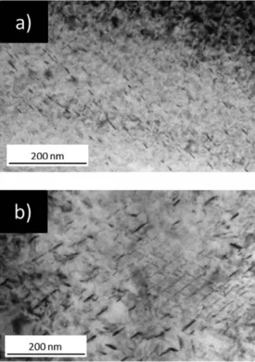
3.2.1.1. Influence of the temperature at a dose of 3 dpa. After irra
diation, a high density of small defects were observed in Ti6-4 alloy
as seen on Fig. S. At low temperature of irradiation (300 °C), as
observed on Fig. Sa, the microstructure of defects ( <a>-type loops and black dots) was so dense that almost no details can be resolved by TEM. The <a>-type loops were very small ( <!>m-7 nm) and very numerous ( density-1022 m-3).6 After irradiation at 430 °C (Fig. Sb),
the microstructure of Ti6-4 alloy was similar to that of the sample irradiated at 300 °c, but the <a> loop mean diameter seemed slightly higher (-1.5 times higher) and their density seemed slightly lower. In both cases, the high density of loops restricted the observation of the precipitates and possible dislocations.
5 The annealing was carried out at 450 °C and not at 430 °C, because 450 °C was
the targeted irradiation temperature.
6 Only defects with a diameter higher than 3 nm were considered in the counting
a lamellar phase 13 phase
a nodular phase
Fig. 3. TEM micrographs before irradiation of Ti6-4 alloy: a) a. nodular and lamellar phases surrounded by � phase and b) Dislocations forming sub-grain boundaries in nodular phase. Solid line separates the nodular a. phase and dotted lines the sub grains.
3.2.1.2. Influence of dose and flux. At low irradiation temperature
{300 °C), the defects ( <a>-type loops and black dots) were small and present in great density. Number density and mean size seemed similar whatever the dose and the flux as seen by com parison of Figs. Sa, 6a and 6b.
After irradiation at 430 °C two different kinds of <a>-type mi crostructures had to be considered. The first one, with a high density of small <a> loops, masking the possible dislocations, was only observed after irradiation at 3 dpa high flux (Fig. Sb). The second one was evidenced after a dose of 0.6 dpa high and low flux and consisted of a tangled <a> dislocation network associated with <a>-type dislocation loops (Fig. 7). The observation of the dislo cation network means a lower density of <a>-type loops after the dose of 0.6 dpa than after the dose of 3 dpa. After irradiation at the dose of 0.6 dpa high flux, this lowering of the <a>-type loop number density was not sufficient to be quantitatively measured {Table S) and consequently the tangled dislocations were hardly perceptible {Fig. 7a). These <a>-type dislocation loops seemed to be slightly Jess numerous in the case of low irradiation flux. Indeed dislocations that are hardly perceptible at high flux, are more noticeable at low flux {Fig. 7b ).
3.2.2. Radiation-induced predpitates
The crystallography of the radiation-induced precipitates was identified thanks to electron diffraction patterns. These diffraction patterns could be indexed as a � phase with a BCC crystallographic structure. In Fig. 8 can be observed an example of diffraction
pattern of the 11. irradiated phase superimposed with those of the
precipitates. The 11. phase (HCP) was oriented according to the
b)
1µm
Fig. 4. TEM micrographs showing dislocation pileups: g = 1010 B- [1213] in Ti6-4 alloy a) as received b) after thermal treatment 6 h at 450 °C.
Fig. 6. <a> loops in the rJ. phase, by TEM, g = 1011 B -[1210], for Ti6-4 alloy irradiated at the dose of 0.6 dpa and at the temperature of 300 °C: a) high flux and b) low flux.
Fig. 7. <a> loops in the rJ. phase, by TEM, g = 1011 B-[1210], for Ti6-4 alloy irradiated at the dose of 0.6 dpa and at the temperature of 430 °C: a) high flux and b) low flux.
B = [1123] zone axis. The precipitates were indexed as � phase (BCC) oriented according to the B = [11Î] zone axis. Indexation of the two phases in this pattern gave the following crystallographic orientation relationships:
B '°" [1123]'1. '°" [11Î]p;
(lÎ00) rJ. 3.5° from (lÎ0)p; (lOÎÎ)rJ.1-2° from (101 )p; (0lÎÎ)rJ. 7.5°
from (011)p
According to a stereographic projection, these relationships are
consistent with the well-known Burgers orientation relation [8],
which gives similar relationships. Fig. 8 shows a diffraction pattern
Fig. 8. Diffraction pattern B-[1123]: superposition of the rJ. phase (blue dotted lines)
and the P phase ( continuous red lin es) patterns. The ix phase corresponds to the matrix
and the P phase to the precipitates. Sample irradiated at the dose of 3 dpa and at the temperature of 430 °c, high flux. (For interpretation of the references to colour in this figure legend, the reader is referred to the Web version of this article.)
of the sample irradiated at 430 °C at the dose of 3 dpa with a high
flux. The indexed variant corresponds to the Vl variant described in the experimental procedures. Diffraction spots for precipitates
were detected for ail the irradiation conditions at 430 °C.
3.2.2.1. Influence of the temperature at the dose of 3 dpa, high flux 3.2.2.1.1. Occurrence. The precipitates were evidenced by TEM
after irradiation at 430 °C, at the dose of 3 dpa, as it can be seen on Fig. 9. Six different crystallographic orientations were predicted by the Burgers relation and were indeed indexed on the diffraction diagrams thanks to stereographic projections. But only three different spatial orientations of the particles were observed on the micrographs regardless of the sample orientation. It means that one spatial orientation corresponds to a couple of crystallographic orientations that cannot be distinguished from each other on bright field micrographs. Thus it was necessary to check on the diffraction
Fig. 9. TEM micrograph of radiation-induced precipitates into the rJ. phase, B-[1123],
diagrams that only one variant of the couple was in contrast before the counting of the particles. The three spatial orientations are
indicated by the numbers one to three on Fig. 9. The first spatial
orientation (1 on Fig. 9) includes the Vl variant as described in the
experimental procedures and on Fig. 8. The second spatial orien
tation (2 on Fig. 9) includes the V2 variant. None of the crystallo
graphic variants of the third spatial orientation (3 on Fig. 9) is oriented near a zone axis orientation and the corresponding pre cipitates are almost out of contrast on Fig. 9.
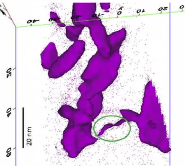
The TEM technique did not allow us to observe the radiation induced precipitates after irradiation at 300 °C. In contrast, the APT technique, by a very fine chemical analysis, evidenced them for the first time at this low irradiation temperature condition. As an example, a 3D reconstruction of the vanadium distribution in the a. matrix of the Ti6-4 alloy after irradiation at the dose of 3 dpa and at
both temperatures of 300 and 430 °C is given on Fig. 10.
In the following the local rise of vanadium is supposed to indi cate the shape of the precipitates. The APT analysis confirmed the presence of at least three spatial variants at 430 °C as seen by TEM
(numbers one to three on Fig. 10b).
3.2.2.1.2. Morphology, size and number density. The shape of the precipitates was delimited by an isosurface of vanadium in APT analyses. After irradiation at 430 °C (Fig. 12) the precipitates looked obviously platelet-like oriented along different orientations. After irradiation at 300 °C, the small size of the precipitates made it difficult to appreciate their true shape and the APT technique can introduce artefacts. Nevertheless they looked much Jess elongated after an irradiation at 300 °C than after an irradiation at 430 °C and
'f 'f 'f "
..
.
': ': 'f 'f 'f 20nm 20nm 40nm 40nm 60nm 60nm 80nm 80nm 100nm 100nm 20nm 20nm 40nm 40nm 60nm 60nm 80nm 80nm 100nm 100nmsome of them looked round-shaped (Fig. 11 ). The elongated
morphology of such particles has been usually attributed to an attempt to minimize the interface energy or to anisotropie diffusion of point defects [31,32]. The interface energy could be different for smaller particles compared to bigger ones and the diffusion pro cesses are slower at 300 °C than at 430 °C. This could explain the difference in shape of the particles between the irradiation temperatures. E C: 0 N 0 N 0 'If
Fig. 11. Precipitates after irradiation at 300 °C for a dose of 3 dpa high flux (APT an alyses). Isosurface V= 10 at.%.
� '/ 'f ': 'f 'f 'r 'l" '/ 'f 'f ': 20nm 40nm 60nm 80nm 100nm
a)
"
..
.,
20nm V 40nm 60nm 80nm 100nmb)
Fig. 10. Needle tip 30 reconstruction (APT analysis ): spatial distribution of titanium, aluminum and vanadium in Ti6-4 alloy irradiated at the dose of 3 dpa, high flux, at the temperature of: a) 300°C and b) 430°(.
1 )
.
�
b) :;,,,, -� ,. - , ,-. '-. 20 nm 0Fig. 12. Platelet-like precipitates after irradiation at 430 °C for a dose of 3 dpa high flux (APT analysis): a) top view, b) edge-on view. Isosurface V= 17 at.%.
The size and the density of the precipitates seemed to be highly
dependent of the temperature. As seen on Fig. 10, the particles were
smaller and much more numerous after irradiation at 300 ac than after irradiation at 430 ac. A mean diameter of 5 nm and a number
density of about 1024 m-3, was measured by APT, after irradiation at
300 ac. The small size of these precipitates could explain why they were not observed by TEM: the resolution of the microscope (Jess than 1 nm) would permit to image such small particles, but their diameter was similar to that of <a> loops and it appeared very difficult to distinguish them from the <a>-loop contrast. In addi tion when the
g
= 0002 diffracting vector was used, the <a>-loop contrast disappeared but the precipitates were masked by a contamination and an oxidation contrast. After an irradiation at 430 ac, the mean size was about twice as big as after an irradiation at 300 ac, and the number density was six time lower, as seen inTable 6. Precipitates were platelets with a mean length of about 10 nm. The length distribution of the particles is given in the his
tograms of Fig. 13. They confirm the increase of the particles size
with the temperature and show a widening of the size distribution of the precipitates.
In addition to the precipitation, channels with a higher vana dium content than the a. matrix was observed after irradiation at 430 ac by APT. None of these channels could be noticed after irra
diation at 300 ac. Fig. 14 gives an example of one of these channels
after irradiation at 430 ac for a dose of 3 dpa.
3.2.2.1.3. Chemical aspects. Table 7 gives the chemical compo sitions from the APT analyses of the a. phase in the non-irradiated (as-received) Ti6-4 alloy, as well as those of the a. matrix and B precipitates in the irradiated alloy at 300 ac and 430 ac for a dose of
50 45 40 � � 35 30 25 G) 20 15 10 5 0 10
"
"
� 43o•c - 3 dpa - 430°c -0.6 dpa C=:J 300°c - 3 dpa••
Preclpltate length (nm)"
Fig. 13. Length distribution of the radiation-induced precipitates deterrnined by APT analyses after irradiation with high flux in Ti6-4 alloy.
3 dpa. The measurements are compared with the EPMA analyses of the B phase in the as-received state. Attention was paid to check that the mean chemical composition in the analyzed volume is that of the a. globular phase determined by EPMA analysis. Furthermore, no significant difference in solute elements was found between globular and lamellar a. phase.
After irradiation at the low temperature of 300 ac and at the dose of 3 dpa, the precipitates were rich in vanadium (B-stabilizer) with 45 wt%. This high vanadium content was far superior to the
vanadium content of the native B-phase (Table 7) and was associ
ated to a depletion of vanadium in the parent a. phase. Indeed, at the non-irradiated state, the a. phase was composed of 2.7 wt% V whereas in the irradiated state at 300 ac, the parent a. phase con tained no more than 1.6 wt% V. The aluminum content seemed on the contrary slightly lower in the precipitates than in the parent a. phase and this difference confirmed the a.-stabilizer character of this element. At the non-irradiated state, the a. phase contained 6.7 wt% Al whereas at the irradiated state at 300 ac, the aluminum content was 6.9 wt% in the parent a. phase and 4.7 wt% in the pre cipitates. In the case of the iron content, the results were in the scattering of the measure and we cannot conclude on the parti tioning of this element. By increasing the irradiation temperature ( 430 ac), a higher vanadium content than at 300 ac, with about 50 wt% was measured in the precipitates. The vanadium content of the parent a. phase was about 1 wt%. There was no significant change of the aluminum and iron contents between the irradiated state at 300 ac and 430 ac. Lower vanadium content was noticed in
�
E ..
C
�
Fig. 14. Vanadium channel observed by APT analysis (isosurface V= 12 at.%.) in Ti6-4 alloy irradiated at 430 °C for a dose of 3 dpa.
the channels observable after irradiation at 430 °C than in the precipitates (isosurface V= 12 at. %). Thus the V-rich channels can be unequivocally be discerned from the precipitates by their lower vanadium content.
3.2.2.2. Influence of dose and flux at 430 °C. Because the
irradiation-induced precipitates were not observable by TEM after irradiation at 300 °c, and because APT analyses were conducted only for the dose of 3 dpa with high flux after this low irradiation temperature of 300 °c, the influence of dose and flux could only be analyzed after irradiations at 430 °C.
For the doses of 3 dpa and 0.6 dpa (high flux at 430 °C), both APT and TEM techniques were carried out. For both doses, no real change in number density and length of the precipitates was seen
by APT (Table 6). TEM observations confirmed the APT analyses
(Table 8). The vanadium-rich channels observed after a dose of 3 dpa at 430 °c (Fig. 14) were noticed after the dose of 0.6 dpa as well.
When Tables 6 and 8 are compared, there is a factor 2.5 in the
number density of precipitates obtained by APT and TEM. The dif ference can be explained by the different analysis scales of the two techniques and by the difficulty to image the particles due to the <a> contrast and to the oxidation and the contamination of the thin foils. Generally speaking TEM counting should not be considered as an absolute result, and ail the measures should be done in the same conditions to be comparable. The conditions to image the pre cipitates in the present paper (bright field imaging with a magni fication of 60 k) appeared as a good compromise between statistical
Fig. 15. TEM micrographs of precipitates in Ti6-4 after irradiation at 430 °C, by TEM,
g
= 1011 B-[1-213]: a) 0.6 dpa high flux, b) 0.6 dpa low flux.considerations, facility, timeliness of the data, and precision of the measures. Dark field images with a higher magnification would probably have permitted to count a bigger number of precipitates. The size of the particles were similar with both techniques.
No APT analyses were conducted on the sample irradiated at the dose of 0.6 dpa with a low flux, but TEM observations of this sample were compared to that of the samples irradiated with a high flux. As
seen on Fig. 15, the precipitates seemed to be longer with the low
flux irradiation (Fig. 15b) compared to the high flux (Fig. 15a) for the
same dose. This was confirmed by the quantitative results (Table 8).
In the case of the low flux, the precipitates were more than two times Jess numerous than in the case of the high flux irradiation conditions and their mean size (both length and width) was about twice as big. In addition, the lower density of <a>-type loops in the lower flux sample (§ 3.2.1.2) allowed to visualize the precipitates better and to highlight a higher density of precipitates on the native
dislocation network (arrowed Fig. 16).
4. Discussion
Irradiation produces a great density of point defects (PDs), va cancies and self-interstitial atoms, in displacement cascades. Then PDs can be annihilated either by mutual recombination or by diffusion to the sinks. The remaining PDs can create bigger defects (clusters, precipitates, loops), inside the cascades thanks to particle shocks, or outside the cascades thanks to diffusion and segregation phenomena. The first process will be named "ballistic effect" as opposed to the diffusional process, in the following. At low tem peratures vacancies are immobile, PDs are annihilated mainly in the cascades by mutual recombination. At low temperatures the diffusion and segregation processes are very low and the defects are
mainly due to displacement cascades [15,33].
During an irradiation at 300 °C, no notable influence of the dose and flux (for the considered doses and fluxes ranges) was noticed on the <a>-type defects in the Ti6-4 alloy. This phenomenon was already observed by the authors in a commercially pure T40 a alloy
[16]. As mentioned previously, the irradiation temperature of
Fig. 16. TEM micrograph of a preferential precipitation on the native dislocation network.
300 ac corresponds to -250 ac in reactor. Thus, the irradiation conditions and the observed microstructure with a very fine and dense dispersion of <a>-type loops seem to correspond to the "low-temperature regime" described by Zinkle et al. for austenitic stainless steel [34]. In the "low temperature regime" the punctual defects are not very mobile and the irradiation defect density and size reach a saturation at a relatively low dose. In this domain, the microstructure is relatively insensitive to variations in the tem perature, the dose, and the dose-rate. The microstructure of defects after ion irradiation at 300 ac is similar to those observed with neutrons by Tahtinen et al. [6,7] (Tirr - -50 ac), and by Kozhenikov
[2] (Tirr = 200 ac and 250 ac), with a very high density of small
defects. The structure is so dense that no details can be resolved as seen byWilkes et al. [14] in a Ti6-4 alloy irradiated by ions at 250 ac and 350 ac ( corresponding to about 200 ac and 300 ac in neutron
irradiation with Equation (1) §2). The difference in the defect
number density and size measured in the previous studies (5 x 10²³ m-3, 2-3 nm [21) and in this work (Table 5) is probably
due to the fact that only defects with a diameter higher than 3 nm were counted in this study.
The influence of raising the irradiation temperature up to 430 ac was a lowering of the <a> loops density and an increase of their mean diameter. These results are consistent with those obtained by P. Wilkes et al. [14] in a Ti6-4 alloy irradiated by heavy ions at 250, 350 and 450 ac. In addition, a lower flux seemed to enhance this temperature effect. Both these phenomena were seen previously
with a commercially pure T40 a. alloy [16], but were very significant
in T40 alloy in the same irradiation conditions whereas they
appeared very modest in Ti6-4 alloy as seen in Table 5.
In the case of the T40 a. alloy [16], the irradiation conditions and the observed microstructures with a tangled <a> dislocation network associated with <a>-type dislocation loops, was stated to correspond to the "high-temperature regime" described by Zinkle et al. [34]. In this "high temperature regime", the punctual defects are more mobile than in the "low temperature regime" and diffuse to be annihilated at sinks or agglomerate into bigger defects. In this regime, raising the irradiation temperature induces a lowering of
the defect supersaturation [33], enhances mutual recombination or
annihilation to the sinks thanks to faster diffusion processes [35]
and thus reduces the loop nucleation incidence. In addition, it en hances the diffusivity of the species and promotes loop growth. Therefore, in this "high temperature regime" the size and density of the defects are drastically dependent on the temperature. Furthermore, as said in §2, a coupling between the flux and the temperature to obtain a given microstructure is evidenced in the literature [15,19]. For the same ion irradiation temperature, lowering the flux should lead to a microstructure representative of
a higher neutron irradiation temperature. According to Equation (1)
the rise in the "neutron equivalent" temperature for an ion irradi ation at 430 ac is about 25 ac.
In the case of the Ti6-4 alloy observed in this study, the irradi ation conditions seem to correspond to the "high temperature regime", but the microstructure with a high density of small <a> type loops, after irradiation at the dose of 3 dpa with a high flux, corresponds to the "low temperature regime". Thus it can be assumed that the difference in composition of the two alloys in duces a shift in the frontier between the two "regimes" toward the higher temperatures for the Ti6-4 alloy compared to the T40. The Ti6-4 alloy is probably in an intermediate domain between the "high temperature" and the "low temperature" regime in the pre sent irradiation conditions.
In addition to <a>-type dislocation loops, a fine precipitation of vanadium-rich B phases inside the a. phase has been observed after irradiation. The formation of the B precipitates results from the decomposition of the supersaturated a. phase that can happen by
two usual ways: spinodal decomposition or nucleation. Spinodal decomposition can occur for large supersaturation. Local segrega tion in solutes can be enhanced by the inverse Kirkendall effect [15,36]. Because the diffusion of vacancies induces a solute flux in the opposite direction, solute elements that diffuse the most rapidly will be depleted at sinks (grain boundaries, dislocations, cavities and interfaces) and, on the contrary, slower diffusers will segregate at sinks. In addition, the interstitial diffusion to the sinks conducts to the diffusion of small size solutes by a dragging effect phenomenon, and can conduct to local segregations of these sol utes at sinks. These two phenomena induce enriched and depleted zones in solute elements [15,37,38] that are called Radiation
Induced Segregation (RIS) [33,39,40]. The vanadium is a small so
lute and is a slower diffuser than aluminum. Thus enrichment of vanadium, which segregates, can be assumed to exist and is
confirmed, as shown in Figs. 14 and 16, by segregations in vanadium
observed by APT and TEM after irradiation at 430 ac. Consequently, the a. phase can be considered as unstable because a local segre gation in vanadium will cause the total free energy to decrease, which takes place only in the miscibility region where the free energy curve has a negative curvature. A two-phase mixture gradually emerges by the continuous growth of an initially small amplitude fluctuation in the inhomogeneous a. phase. However, such a scenario cannot be considered due to the nonisomorphic nature of the two phases. The probable mechanism that explains the refined and homogeneous distribution of vanadium-rich B phases inside the a. phase is therefore the heterogeneous nucle ation. The heterogeneous nucleation can be viewed as a time dependent process in which vanadium drags induced by RIS or vanadium-rich clusters induced by the ballistic phenomena act as catalysts for increasing the inherent nucleation rate by reducing the free energy of nucleus formation. The sensitive temperature dependence of nucleation rate is also clearly highlighted. In fact, when the irradiation temperature decreases, the diffusing length of punctual defects decreases, thus one expects a high nucleation rate and a slow growth of the precipitates. The rise in the precipitate size associated with a lowering of their density with a rise in the irradiation temperature was evidenced here and was also observed by different authors [9-11 ].
The chemical composition of the B precipitates is clearly enriched in vanadium as compared to the native B phase. The B precipitates exhibit a concentration of 50 wt% V and 4.2-4.3 wt% Al after irradiation at 430 ac and 45 wt% V and 4.7 wt% Al at 300 ac. The calculated equilibrium concentration obtained using Thermo Calc software and Saunders titanium public database is respectively 56 wt% V, 3 wt% Al at 430 ac and 80 wt% V, 1.6 wt% Al at 300 ac. The RIS phenomenon is dominated by the solute diffusion process. It supposes an equilibrium concentration of the solute elements in the precipitates and the existence of segregations at the defect sinks. In addition the RIS phenomenon occurs in a particular tem perature/flux domain depending on the fusion temperature of the material [33,39]. In the case of Ti the RIS is expected at 430 ac in the present irradiation conditions (temperature and flux). Furthermore the values of the B precipitate solute concentrations as well as the parent a. phase are quite close to, but somewhat smaller than, the calculated equilibrium concentrations after an irradiation at 430 ac. Finely, some evidence of segregations at sinks was observed (het erogeneous precipitation at grain boundaries by MET and V-rich channels by SAT) with the 430 ac irradiation temperature. This finding supports the hypothesis that precipitate nucleation and growth at 430 ac are dominated by the RIS that reduces the nucleation barrier and enhances the solute diffusion. The RIS phenomenon supposes that particles nucleation occurs at sinks. The native dislocations are usually considered as defect sinks and appeared clearly in this study as nucleation sites for the
radiation-induced precipitates during irradiation at 430 °C (Fig. 16). The radiation-induced particles were observed not only on the native dislocation network but also in the a matrix with a uniform spatial distribution and with a density similar to that of the <a>-type loops. The only uniformly distributed defect sinks and, as a consequence, the only uniformly distributed potential sites for the precipitate nucleation seems to be the <a>-type loops. Thus <a> loops are suspected to be nucleation sites for the precipitates. On the contrary, the RIS was not expected in the temperature/flux domain of the present irradiations at 300 °C with the high flux conditions because at low temperatures the diffusion and segre gation processes are very low and the defects are mainly due to displacement cascades [15,33]. In addition, after irradiation at 300 °C, the chemical composition was quite far from the equilib rium values calculated with ThermoCalc and no vanadium rich channels were seen by APT. Thus there was no evidence of the RIS phenomenon at 300 °C and we can suspect that the nucleation of the vanadium-rich precipitates at 300 °C was dominated by the mechanism of vanadium-rich cluster formation by ballistic effects in the cascades and not by the solute diffusion (RIS). However, it should be kept in mind that the accuracy of APT measurements is lower at 300 °C than at 430 °C, because the precipitates are smaller. In addition, predicted thermodynamic equilibrium values at 300 °C were extrapolated from databases at 600 °C and may be over estimated. What is more, the temperature/flux conditions at 300 °C are not very far from the theoretical frontier of the RIS domain (calculated from the fusion temperature), and the effective frontier can be at lower temperatures than predicted. Thus the RIS phe nomenon cannot be completely excluded to explain the nucleation of the particles at 300 °c.
On another hand, as said above, the RIS is dependent on the flux
[33] and an influence of the flux on the precipitation is expected
after irradiation at 430 °c. With a lower flux, the point-defect for mation-rate is lower and the probability of point-defect recombi nation in the cascades is lower. Thus the diffusion to the sinks is promoted over recombination as if the temperature was increased
[15]. Therefore the decrease in flux is equivalent to a rise in tem
perature and gives bigger and Jess numerous precipitates as seen here.
5. Conclusion
The microstructure observed in reactors with neutrons in both the "low" and the "high" temperature domain was successfully reproduced by ion irradiations, with the occurrence of <a>-type defects and radiation-induced B phase precipitates. The role of temperature, dose and flux were experimentally studied by TEM and APT. The following conclusions can be drawn:
- At 300 °C, the microstructure of irradiation defects consisted in a very dense distribution of small defects, as seen after irradiation in reactors at temperatures below 250 °C. There was no notable influence of the dose and flux for the considered doses and fluxes ranges on the <a>-type defects at this low irradiation temperature.
- The influence of raising the irradiation temperature from 300 °C up to 430 °C was a lowering of the density and an increase of the mean diameter for <a>-type loops and radiation-induced pre cipitates. A lower flux seemed to enhance this temperature ef fect. These phenomena were very significant for precipitates whereas they appeared very modest for <a>-type loops. - The nucleation and growth of the vanadium-rich precipitates
are probably dominated by the mechanism of vanadium-rich clusters formation by ballistic effects at 300 °C and by the Ra diation Induced Segregation (RIS) phenomenon at 430 °C.
Data availability statement
Ali data generated or analyzed during this study are included in this published article.
Aclmowledgement
The authors acknowledge the support of the French National Research Agency (ANR), France, under grant ANR-12-RMNP-0005 (project TESAMI, meaning Titanium and Its Alloys under Irradia tion) and the partners of the project: Naval Group, CEA, Techni cAtom, TIMET, Neotiss, EVEA, ICB and SUBATECH, France.
The authors would like to warmly thank the staff of JANNUS facility for their assistance during ion irradiations.
The authors are grateful to the staff (CEA-DANS-DEN-DMN) for their assistance in the area of TEM examination: Th. Vandenberghe, B. Arnal.
The authors acknowledge financial support from the CNRS-CEA "METSA" French network (FR CNRS 3507) for the Atom Probe ex periments conducted on the METSA platform.
The authors are grateful to TechnicAtom for the activation measurements.
References
[1] R.H. Jones, LA. Charlot, Microstructure of irradiated Ti-70A and Ti-6Al-4V, J. Nucl. Mater. 91 (1980) 329-335.
[2] O.A Kozhenikov, E.V. Nesterova, V.V. Rybin, 1.1. Yarmolovich, Influence of neutron irradiation on deformability and fracture micromechanisms of tita nium a-alloys, j. Nucl. Mater. 271-272 (1999) 472-477.
[3] B.S. Rodchenkov, A.V. Koslov, Yu G. Kuznetsov, G.M. Kalinin, YuS. Strebkov, Irradiation behaviour of titanium alloys for !TER blanket modules flexible attachment, J. Nucl. Mater. 307-311 (2002) 421-425.
[4] B.K. Singh, V. Singh, Effect of fast neutron irradiation on tensile properties of AIS! 304 stainless steel and alloy Ti-6Al-4V, Mater. Sei. Eng. 528 (2011) 5336-5340.
[ 5] D.R. Duncan, R.j. Puigh, E.K. Opperman, Titanium alloy tensile properties after neutron irradiation, J. Nucl. Mater. 103-104 (1981) 919-924.
[6] S. Tahtinen, P. Moilanen, B.N. Singh, DJ. Edward, Tensile and fracture tough ness properties of unirradiated and neutron irradiated titanium alloys, J. Nucl. Mater. 307-311 (2002) 416-420.
[7] S. Tahtinen, P. Moilanen, B.N. Singh, Effect of displacement dose and irradia tion temperature on tensile and fracture toughness properties of titanium alloys, J. Nucl. Mater. 367-370 (2007) 627-632.
[8] W.C. Burgers, On the process of transition of the cubic-body-centered modi fication into the hexagonal-close-packed modification of zirconium, Phys. 1 (nd) 561-586.
[9] G. Ayrault, Radiation-induced precipitation in single- and dual-ion irradiated Ti-6Al-4V, J. Nucl. Mater. 113 (1983) 1-13.
[10] P. Manny, T. Legey, Impact of irradiation on the tensile and fatigue properties of two titanium alloys, j. Nucl. Mater. 296 (2001) 155-164.
[11] D.L Plumton, G.L Kulcinski, R.A Dodd, Radiation induced precipitation in 9 MeV Al ion irradiated Ti-6Al-4V, J. Nucl. Mater. 144 (1987) 264-274. [12] D.L Plumton, G.L Kulcinski, R.A. Dodd, Phase transformations in ion irradiated
Ti-6242s, j. Nucl. Mater. 144 (1987) 252-263.
[13] S.C. Agarwal, G. Ayrault, D.I. Patter, A. Taylor, F.V. Nolfi, Microstructure of single and dual-ion irradiated Fe-20Ni-15Cr and Ti-6Al-4V alloys, J. Nucl. Mater. 85-86 (1979) 653-657.
[14] P. Wilkes, G.L Kulsinski, Heavy ion irradiation of a Ti-6Al-4V alloy, J. Nucl. Mater. 206 (1978) 427-430.
[15] G.S. Was, Irradiation-induced voids and bubbles, in: Fundamentals of Radia tion Materials Science, Springer, Berlin, Heidelberg, New York, 2007, pp. 388-390.
[16] E.Jouanny, S. Doriot,J. Malaplate, M. Dehmas, L Allais, M. Le Thuaut, T. Millot, Evolution of defects in titanium grade 2 under n2+ ion irradiation, J. Microsc.
255 (3) (2017) 275-286.
[17] S. Pellegrino, D. Bachiller-Perea, j. Mater. Res. 30 (2015) 1183-1194. [18] Y. Serruys, P. Trocelier S. Miro, E. Bordas, M.-0. Ruault, O. Kaïtasov, S. Henry,
O. Leseigneur, T. Bonnaillie, S. Pellegrino, S. Vaubaillon, D. Uriot, JANNUS : a multi-irradiation platform for experimental validation at the scale of the atomistic modeling, J. Nucl. Mater. 386-388 (2009) 967-970.
[19] L.K. Mansur, Correlation of neutron and heavy-ion damage: II. The predicted temperature shift if swelling with changes in radiation dose rate, j. Nucl. Mater. 78 (1978) 156-160.
[20] D. Connetable, J. Hurz, E. Andrieux, C. Mijoule, First-principles study of diffusion and interactions of vacancies and hydrogen in hcp-titanium, J. Phys. Condens. Matter 23 (2011) 1-14.
[21] R.F. Egerton, Electron Energy-loss Spectroscopy in the Electron Microscope, second ed., Plenium Press, New York, 1996.
[22] P.A. Crozier, Measurement of inelastic electron scattering cross sections by electron energy-loss spectroscopy, Philos. Mag. A 61 (1990) 331-336. [23] D.R.G. Mitchell, Determination of mean free path for energy Joss and surface
oxide film thickness using convergent beam electron diffraction and thickness mapping: a case study using Si and P91steel, J. Microsc. 224 (2006) 187-196. [24] C.W. Lee, Y. lkematsu, D. Shindo, Measurement ofmean free paths for inelastic electron scattering of Si and Si02,J. Electron. Microsc. 51 (3) (2002) 143-148. [25] T. Leguey, R. Schaublin, P. Marmy, M. Victoria, Microstructure of Ti5Al2.5Sn and Ti6Al4V deformed in tensile and fatigue tests, J. Nucl. Mater. 305 (2002) 52-59.
[26] G. Lütjering, Property optimization through microstructural control in tita nium and aluminum alloys, Mater. Sei. Eng. 263 (1999) 117-126.
[27] P. Castany, F. Pettinari-Sturmel, J. Crestou, J. Douin, A. Coujou, Experimental study of dislocation mobility in a Ti-6Al-4V alloy, Acta Mater. 55 (2007) 6284-6291.
[28] V. Hasija, S. Ghosh, M.j. Mills, D.S.Joseph, Deformation and creep modeling in polycrystalline Ti-6Al alloys, Acta Mater. 51 (2003) 4533-4549.
[29] T. Neeraj, M.J. Mills, Short-range order (SRO) and its effect on the primary creep behavior of a Ti-6wt.%Al alloy, Mater. Sei. Eng. 319-321 (2001) 415-419.
[30] M. Brandes, M.j. Mills, j.C. Williams, The influence of slip character on the creep and fatigue fracture of an rx Ti-Al alloy, Metall. Mater. Trans. 41A (2010)
3463-3472.
[31] A. Sarce, Stability of precipitates in the anisotropie rx-Zr matrix under irradi ation, J. Nucl. Mater. 185 (1991) 214-223.
[32] A.A. Turkin, A.V. Buts, AS. Bakai, Construction of radiation-modified phase diagrams under cascade-producing irradiation: application to Zr-Nb alloy, J. Nucl. Mater. 305 (2002) 134-152.
[33] M. Nastar, F. Soisson, Comprehensive Nuclear Materials 1 : Basic Aspects of Radiation Effects in Solids/Basic Aspects of Multi-scale Modeling, Elsevier, 2012, pp, 471-496.
[34] S.J. Zinkle, P.J. Maziasz, R.E. Stoller, Dose dependence of the microstructural evolution in neutron-irradiated austenitic stainless steel, J. Nucl. Mater. 206 (1993) 266-286.
[35] M. Griffiths, D. Faulkner, R.C. Styles, Neutron damage in rx-titanium, j. Nucl. Mater. 119 (1983) 189-207.
[36] K. Nordlund, R.S. Averback, Inverse kirkendal mixing in collision cascades, Phys. Rev. B 59 (1999) 20-23.
[37] P. Hosemann, Rev. Accelerator Sei. Technol. 4 (2011) 161-182.
[38] K.C. Russell, Phase stability under irradiation, Prog. Mater. Sei. 28 (1984) 229-434.
[39] P.R. Okamoto, LE. Rehn, L.E. Rehn, Radiation-induced segregation in binary and temary alloys, J. Nucl. Mater. 83 (1979) 2-23.
[40] R. Cauvin, G. Martin, Radiation induced homogeneous precipitation in un dersaturated solid-solutions, J. Nucl. Mater. 83 (1979) 67-78.

![Fig. 4. TEM micrographs showing dislocation pileups: g = 1010 B- [1213] in Ti6-4 alloy a) as received b) after thermal treatment 6 h at 450 °C](https://thumb-eu.123doks.com/thumbv2/123doknet/14618365.733392/8.892.201.711.626.863/micrographs-showing-dislocation-pileups-alloy-received-thermal-treatment.webp)
![Fig. 8. Diffraction pattern B-[1123]: superposition of the rJ. phase (blue dotted lines) and the P phase ( continuous red lin es) patterns](https://thumb-eu.123doks.com/thumbv2/123doknet/14618365.733392/9.892.55.424.767.1072/diffraction-pattern-superposition-phase-dotted-lines-continuous-patterns.webp)