Université de Montréal
Effect of foot angle changes on body joints and segments during standing and running
Effet de changement d’angle au pied sur les articulations et les segments lors de l’équilibre debout et de la course
by
Mansour Eslami
Département de Kinésiologie
Thesis submitted to the Faculté des études supérieures in
partial fuffiulment of the requirements for the degree of Philosophiae Doctor (Ph.D) en sciences de l’activité physique
April, 2007
GV
U5H
dl
de Montréal
Direction des bibliothèques
AVIS
L’auteur a autorisé l’Université de Montréal à reproduite et diffuser, en totalité ou en partie, pat quelque moyen que ce soit et sut quelque support que ce soit, et exclusivement à des fins non lucratives d’enseignement et de recherche, des copies de ce mémoire ou de cette thèse.
L’auteur et les coauteurs le cas échéant conservent la propriété du droit d’auteur et des droits moraux qui protègent ce document. Ni la thèse ou le mémoire, ni des extraits substantiels de ce document, ne doivent être imprimés ou autrement reproduits sans l’autorisation de l’auteur.
Afin de se conformer à la Loi canadienne sur la protection des renseignements personnels, quelques formulaires secondaires, coordonnées ou signatures intégrées au texte ont pu être enlevés de ce document. Bien que cela ait pu affecter la pagination, il n’y a aucun contenu manquant.
NOTICE
The author cf this thesis or dissertation has granted a nonexciusive license allowing Université de Montréal to reproduce and publish the document, in part or in whole, and in any format, solely for noncommercial educational and research purposes.
The author and co-authors if applicable retain copyright ownership and moral rights in this document. Neither the whole thesis or dissertation, net substantial extracts from it, may be printed or otherwise reproduced without the author’s permission.
In compliance with the Canadian Privacy Act some supporting forms, contact information or signatures may have been removed from the document. While this may affect the document page count, it does net represent any loss cf content from the document.
11
Université de Montréal
Faculté des études supérieures
This thesis entitled:
Effect of foot angle changes on body joints and segments during standing and running
Effet de changement d’angle au pied sur les articulations et les segments lors de l’équilibre debout et de la course
Presented by
Mansour Eslami
Was evaluated by the following examining cornmittee: Luc Proteau. Ph.D
Committee President. Département de Kinésiologie
Paul Allard, Ph.D., P .Eng
Thesis Supervisor, Département de Kinésiologie
françois Prince, Ph.D
Internal Examiner, Département de Kinésiologie
Franck Barbier, Ph.D
External Examiner, Université de Valenciennes
Luc Proteau, Ph.D Representative of the Dean
Le pied contribue à l’équilibre en station debout et participe à une démarche harmonieuse. Un désalignernent du pied et de la jambe pourrait perturber cet équilibre et modifier l’amortissement des chocs et entraîner des charges excessives aux articulations. Les chaussures et les orthèses servent à aligner le pied et la jambe correctement. Malgré le soulagement apparent des symptômes liés aux blessures, près de 40% des coureurs n’en retirent peu ou aucun bénéfice. Les trois études formant le corps de cette thèse portent sur l’effet des modifications de l’alignement du pied et de la jambe sur les articulations et les segments proximaux lors de l’équilibre postural et à la course.
Au moins onze sujets masculins ont participé à ces études. Les mesures de la posture ont été réalisées au moyen dun système vidéo tridimensionnel comprenant cinq caméras. Une cale en bois a été placée sous les côtés antérieur, postérieur, latéral et médial du pied dominant afin de perturber l’équilibre debout sur une jambe. Lors des expériences à la course, des données vidéo et de plate-forme de forces ont été collectées simultanément.
Le premier objectif de cette recherche était de tester comment une cale qui réoriente le pied modifie l’alignement des articulations du membre inférieur, du bassin et du tronc en station debout sur une jambe. Lorsque comparée à la condition sans cale, la variabilité angulaire dans le plan frontal pour l’articulation talo calcanéenne était environ 6 fois plus importante qu’avec une cale médiale. Pour les cales antérieures et postérieures, la variabilité angulaire de la cheville et de la hanche dans le plan sagittal ainsi que celle du basin et du tronc dans le plan transverse était environ 2 à 3 fois plus élevée.
La seconde étude porte sur les mouvements à l’avant et à l’arrière pied et leurs effets sur la rotation tibiale lors de la phase de support durant la course.
À
la réception, le couplage cinématique de l’avant-pied par rapport à l’arrière-pied était déphasé. Au milieu de la phase de support, le couplage devient moins déphasé. Duiv
milieu de la phase de support à la poussée, la déphase se reproduit. Par comparaison à la course avec pieds nus, la course avec sandale a démontré une relation moins déphasée que celte qui était entre l’adductionlabduction à l’avant pied et l’éversionlinversion à l’arrière pied. Il a été démontré que la rotation tibiale n’était pas modifiée par rapport à celle à l’arrière pied lors du contact du talon par le mouvement à l’avant pied dans le plan horizontal.
Le troisième objectif était de tester si l’éversion à l’arrière pied et la rotation tibiale interne agissent sur le moment d’adduction maximal au genou et sur la force de réaction au sol lors de la phase de support à la course. Les mouvements de Parrière-pied et du tibia ont été modifiés avec l’utilisation des orthèses lors des essais à la course. Une corrélation positive a été observée entre le moment d’adduction maximal au genou et l’éversion à l’arrière-pied. Les résultats indiquent qu’une modification du mouvement à l’arrière-pied dans le plan frontal pourrait être associée
à une réduction du moment en adduction au genou excessif mais non à un amortissement de la force verticale de réaction au sol.
En général, ce travail de recherche souligne l’importance du pied en relation à ses articulations et segments proximaux lors de l’équilibre en station debout et lors de la course. Il est anticipé que ce travail pourrait aider les cliniciens à développer de meilleures orthèses.
ABSTRACT
The foot contributes to standing stability and participates to provide a smooth gait. Changes in foot and leg alignment could modify the stabilizing and shock-absorbing role of the lower-limb and, in turn, cause irregular loading on the body joints. Shoewear and foot orthoses have been advocated to alïgn the foot and leg properly. Despite apparent relief of symptoms from injuries, up to 40% of mnners were found to gain littie or no benefit through the application of foot interventions. The three studies comprising the core of this thesis are intended to establish the contributions of the foot-angle changes in relation to the angular variability and amplitude of lower limb joints, during standing and running.
At least eleven able-bodied male subjects participated to these three studies. Posture measurements were perforrned by means of a three-dimensional video-based system consisting of five cameras. A wooden wedge was p!aced under the anterior, posterior, lateral and medial sides of the dominant foot to perturb single-limb stance. In the running experiments, video and force-plate data were collected simultaneously.
The first objective of this research was to see how single-limb standing posture is affected by the lower-limb joints, pelvis and trunk, when a wedge re orients the foot. Compared to the no wedge condition, the frontal plane angle variability for the subtalar joint was about 6 times greater for the medial wedge. For the anterior and posterior wedges, angle variability of the anlde and hip in the sagittal plane and the pelvis and trunk in the transverse plane was about 2 to 3 times higher.
The second study determined the forefoot-rearfoot motion patterns and their effects on tibia! rotation during the stance phase of running. The measure of forefoot rearfoot motion patterns was manipulated by sandal during running. Forefoot-rearfoot coup!ing was more in out-of-phase at heel-strike. This transitioned into an in-phase relationship by mid-stance. From mid-stance to toe-off, this coupling pattern transitioned back to an out-of-phase relationship. The coupling pattern of forefoot adductionlabduction and rearfoot eversionhinversion, was more in-phase during the
vi
heel-strike phase of shod running than in barefoot running. Nevertheiess, there was no statistically significant reduction of tibial internai rotation.
The third specific objective tested the contributions of rearfoot eversion and tibial internai rotation to peak knee adduction moment and ground reaction force during the stance phase of running. Rearfoot and tibial motions were manipulated with the use of foot orthoses during running. A positive coneiation was observed between peak knee adduction moment and rearfoot eversion amplitude. Findings imply that rnodifying rearfoot frontal plane motion with the use of orthoses could be related to a reduction of excessive knee adduction moment but not to a cushioning of the vertical ground reaction force.
In general, this research work underiines the importance of the foot segment in relation to its proximal joints and segments during standing and running. It is anticipated that this work can heip clinicians to deveiop better orthotics.
• Appareils orthopédiques • Articulations • Cinématique • Cinétique • Posture • Avant pied • Arrière pied • Moment au genou
• Rotation tibiale interne
• Force de réaction au sol
viii • Orthotic devices • Joints • Kinematics • Kinetics • Posture • Forefoot • Rearfoot • Knee moment
• Tibiai internai rotation
• Ground reaction force
TABLE CONTENTS TITLE PAGE j COMMITTEE PAGE ii RÉSUMÉ ABSTRACT y MOTS CLÉS vil
KEY WORDS viii
LIST 0F TABLES xii
LIST 0F FIGURES xiii
LIST 0F ARBREVIATIONS xvi
DEDICATION xvii
ACKNOWLEDGEMENTS xviii
Chapter 1
1. INTRODUCTION 1
1.1 Footami Ankle Joints and Axes of Motion 2
1.2 Subtalar Joints and Its Proximal Joints and Segments in Standing
Posture 6
1.3 Forefoot-Rearfoot Coupling Motion and Tibial Rotation during
Running 8
1.4 Rearfoot and Tibial Rotations in Relation to Ground Reaction Forces
and Knee Moments 10
X
Chapter 2
2. REVIEW 0F LITERATURE 13
2.1 Postural Strategies in Maintaining Standing Posture 14 2.2 Lower Extremity Coupling Kinematics during Running 17 2.3 Rearfoot and Tibia Rotations in Relation to Knee Moment and
Ground Reaction Force 22
2.4 Specific Objectives of Thesis 26
Chapter 3
3. MNEMATIC AND MNETIC MODELS 0f THE FOOT AND
ANKLE 2$
3.1 Tibia and Foot Kinematic Model and Three-Dimensional Joint Angle
Calculation 2$
3.1.1 Marker Configuration 30
3.1.2 Global andLocalCoordiitate Systems 33
3.1.2 C’atcutation of Virtuat Markers 36
3.1.4 Joint Angles Jatculation 37
3.1.5 Determination of Foot and Tibia Angutar Vetocities 3$
3.2 Kinetic Analysis of the Ankle and Knee 39
3.2.1 Forces and Moments atthe Ankte and Knee 39
3.2.2 Newton-Euler Inverse Dynainics Method 40
Chapter 4
4. MANUSCRIPT 1
Effect of foot wedge positions on lower-limb joints, pelvis and trunk
Chapter 5
5. MANUSCRIPT 2
Forefoot-rearfoot coupling patterns and tibial internai rotation
during stance phase of barefoot versus shod running 6$
Chapter 6
6. MANUSCRIPT 3
Effect of foot orthoses on amplitude and timing of rearfoot and tibiat motions, ground reaction force and knee moment during running...9$
Chapter 7
7. DISCUSSION 123
7.1 Foot Angle Changes and Variability of Body Joints and Segments
during Single-Limb Stance 123
7.2 Forefoot-Rearfoot Coupling Patterns and Tibial Internal Rotation in
Running 126
7.3 Rearfoot and Tibia] Rotations in Relation to Ground Reaction Force
and Knee Moment During Stance Phase of Running 128
7.4 Limitations 131
7.5 Future Studies 133
Chapter 8
8. CONCLUSION 136
xii
LIST 0F TABLES
Chapter 3
Table 3.1 Anatomical, virtual and technical markers, symbols and their locations
on the tibia, rearfoot and forefoot 32
Chapter 5
Table 5.1 Mean values (standard deviation) of the excursion of rearfoot eversion and tibial internal rotation (degree) in barefoot and shod conditions. .94
Table 5.2 Mean (standard deviation) of the forefoot eversion/inversion and rearfoot eversionlinversion absolute relative angle (degree) across the five intervals of stance phase in barefoot versus shod running 95
Table 5.3 Mean (standard deviation) of forefoot dorsi/plantar flexion and rearfoot eversionlinversion absolute relative angle (degree) across the five intervals of stance phase in barefoot versus shod
running 96
Table 5.4 Mean (standard deviation) of forefoot adductionlabduction and rearfoot eversioWinversion absolute relative angle (degree) across the five intervals in barefoot versus shod running 97
Chapter 6
Table 6.1 Correlation coefficients (r values) and P values between amplitude of rearfoot eversion (EV), tibial internal rotation (TIR), active peak ground reaction force (AVGRF) and knee adduction moment (KAM) in shod and shodlorthoses conditions (P<O,05) 122
LIST 0f FIGURES
Chapter 1
figure 1.1 A dorsal view of foot joints and bones (adapted from Nordin &
Frankel, 2001) 3
figure 1.2 Subtalar jointaxis. A, Sagittal plane axis rises up at a 42° angle from the plantar surface (lateral view). B, Transverse plane (top view). The axis is oriented 16° medial to the midiine of the foot (Manter
1941) 3
Figure 1.3 Longitudinal axis of the transverse tarsal joint. A, Lateral view. B,
Top view (Manter 1941) 4
Figure 1.4 Oblique axis of the transverse tarsal joint. A, Lateral view. B, Top
view (Manter 1941) 4
figure 1.5 Mitered hinge model of leg, ankle, and subtalar joint motion (Nordin
& Frankel, 2001) 5
figure 1.6 Orientation of the calcaneocuboid and talonavicular joints axes in (a) normal, (b) inverted position of foot (Nordin & Frankel,
2001) 7
Chapter 2
figure 2.1 (a) Phase angle plots of normalized angular displacement versus normalized angular velocity curves for rearfoot eversion/inversion, (b) tibial rotation, and (c) the continuous relative phase (CRP) plot for coupling motion of rearfoot eversionlinversion (RF ev/in) and knee ftexionlextension (K fie) (DeLeo et al.,2004) 20
xiv
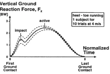
figure2.2 Illustration of impact and active vertical ground reaction force for ten trials at the speed of 4 mIs (Nigg, 2001) 24
Chapter 3
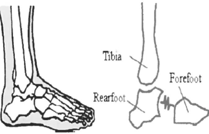
Figure 3.1 Schematic diagram of the three segment model of the foot segments
and tibia 29
figure 3.2 Markers configuration located on the tibia, rearfoot and forefoot based on Kidder et al. (1996) as well as four new virtual markers (O).The alpha-numeric symbols are described Table 3.1 (Kidder et
ai., 1996) 31
figure 3.3 Global coordinate system and local coordinate systems of the tibia (XYZ), rearfoot (xyz) and forefoot (xvz )(Carson et ai., 2001; Wu et
ai., 2002) 33
Figure 3.4 The components of the resultant moment in the joint coordinate
system at the ankle and knee 43
Chapter 4
figure 4.1 Anterior and posterior views of marker placement during barefoot
single-limb stance 63
figure 4.2 Structure of wedge (lateral view) 64
figure 4.3 RMS values and standard deviations of angle changes for the hip and subtalar joints in the frontal plane for ail wedge positions [anterior wedge (AW), posterior wedge (PW), laterai wedge (LW), medial wedge (MW)]. A statistical difference is indicated by (*) in
comparison to the no wedge condition (NW) .65
Figure4.4 RMS values and standard deviations of angle changes in the hip, knee and ankle joints in the sagittal plane for ail wedge positions. A statistical difference is indicated by (*) in comparison to the no
wedge condition (NW) 66
figure 4.5 RMS values and standard deviations of angle changes for the trunk and pelvis in the transverse plane for ail wedge positions. A statistical difference is indicated by (*) in compare to the no wedge
condition (NW) 67
Chapter 5
figure 5.1 Anterior ta) and posterior (b) views of marker placements in barefoot condition. Lateral view in shod condition (c) 92
Figure 5.2 Angle-angle plot for rearfoot eversion/inversion versus tibial internallexternal rotation from heel-strike (HS) to toe-off (TO) in the
shod and barefoot conditions 93
Chapter 6
figure 6.1 Anterior and lateral view of marker placement in the barefoot and
shod conditions 120
figure 6.2 Mean amplitude of (a) rearfoot eversion, (b) tibial internai rotaion, (c) peak knee adduction moment, and (d) peak ground reaction force. (*) indicates statistical differences between shod
O
andxvi
LIST 0F ARBREVATIONS
AGRF Active Ground Reaction Force ANOVA Analysis of Variance
AW Anterior Wedge
COP Centre of Pressure
CRP Continuous Relative Phase
EVITIR Rearfoot Eversion and Tibial Internai Rotation ratio
FFaWab Forefoot AdductionlAbduction
Forefoot Dorsi/Plantar flexion
Forefoot Eversionllnversion
KAM Knee Adduction Moment
LW Laterally Wedge
ML Medially Wedge
PW Posterior Wedge
REV Rearfoot Eversion
Rearfoot Eversionllnversion
RMS Root Mean Square
Praise be to Allait, the Cherisher and Sustainer oflite worlds
This Thesis is dedicated
To memory of my Mom and Father who first taught me the Faith
xviii
ACKNOWLEDGEMENTS
This thesis would flot have been possible without the support and generosity of some very special people who devoted their time and energy to provide me with their valuable contributions.
Many thanks due to my supervisor; Dr. Paul Allard. His belief in me aiways has been an inspiration, and his wisdom, patience and challenging supervision of this thesis, have been extremely indispensable.
A great debt is owed to the Ministry of Sciences, Research, and Technology of han and University of Mazanderan. Their support this year and in years past lias made this Thesis possible.
My family bas been a wonderfuily encouraging; to them and particuiarly to Dr. Aziz Eslami for their enduning support; I am endlessly grateful.
I would like to thank Professors, Franck Barbier, François Prince and Luc Proteau for being members of committee. I appreciate ail the time the members of committee took to read this thesis and for providing their input and thoughts on the subject.
Co-workers and Co-authors, especially Dr. Nader farahpour, Dr. Mickal Begon, Dr. Clarice Tanaka and Sébastien Hinse; their attentive considerations of this project have been extremely heipfui. Thanks to ail of them.
My thanks go to Sainte-Justine Hospital, University of Montreal and Department of Kinesiology for providing journals and references and nice atmosphere which made the research processes and outcomes nicher and more constructive.
Chapter 1
1. INTRODUCTION
The foot is an integral mechanical part of the lower extremity. It contributes to
standing stability and participates to provide a smooth gait. Changes in the atignment
of foot and leg could modify the stabilizing and shock-absorbing role of the lower
limb and, in tum, cause irregular loading on the more proximal parts of the body
(Radin et al., 1991). Shoewear and foot orthoses have been advocated to align the
foot and leg properly. These serve to increase stability during standing and reduce overloading in lower-limb joints during gait (Nigg et al., 2003). foot orthoses,
irrespective of designs or postings, were reported to be ineffective at reducing
postural instability (Hertel et al., 2001). furthermore. despite apparent relief of
symptoms from injuries, up to 40% of ruimers were found to gain little or no benefit
tbrough the application oforthoses (Gross et al., 1991). Thus, an understanding ofthe
interactions of foot function and upper body joints during standing and running is
needed to find better solutions for wedge/orthotic fitting. The three studies
comprising the core of this thesis are intended to establish the contributions of the
foot-angle changes in relation to the angular variability and amplitude of lower-limb
joints, during standing and running.
This chapter describes the anatomy of the foot and ankle related to the
2
proximal joints and segments will be described in maintaining posture during
standing. Then, abnormal motions of the subtalar joint involving excessive rearfoot
and tibia! rotations will be addressed to emphasize the importance of these rotations
in lower-limb injuries. This will be followed by a description of the effect of forefoot
motions on rearfoot and tibia motions during running. The use of foot orthoses in the
prevention rearfoot and tibia! rotation, and their relation to ground reaction forces and
knee moments, will follow. Finally, the overali structure of thesis will be presented.
1.1 Foot and Ankle Joints and Axes of Motion
The foot is comprised of 28 bones and 33 joints. Three major segments make up the
foot, namely forefoot, midfoot and rearfoot. The forefoot includes the five metatarsal,
fourteen phalanges and two sesamoid bones. The navicular, cuboid and three
cuneiform bones make up the midfoot and the rearfoot is comprised of the calcaneus
and talus. The ankle includes the tibia, fibula and talus forming the ankle mortise.
The joints between the base of five metatarsal, cuboid and three cuneiform is termed
the tarsometatarsal joints. The transverse tarsal joint consists of talonavicular joint
and calcaneocuboid joint. The joint between the talus and calcaneus is the subtalar
joint (Figure 1.1). The anide complex consists of the tibiotalar, fibulotalar, and
tibiofibular joints.
The foot acts as a rigid platform in supporting the weight of the entire body,
barefoot on the sand. The transition from rigid lever to shock-absorbing platform
depends on the orientations of rotations axes in subtalar and transverse tarsal joints.
Manter (1941) determined that the subtalar axis of rotation is oriented upward at an
angle of 42° from the plantar surface and medially 16° from the midiine (Figure 1.2).
Inversion and eversion occurs primarily in this axis.
A
B
Figure 7.2 Subtalar joint axis. A, Sagittal plane axis rises up at a 42 angle from the plantar surtace (lateral view). B, Transverse plane (top view). The axis is oriented 16° medial to the
midline of the foot (Manter 7947) Midfoot
Fofoot
Figure 7.7 A dorsal view of foot joints and bones (adapted f rom Nordin & Frankel, 2001)
4
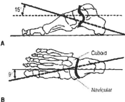
In the transverse tarsal joint, a longitudinal axis and an oblique axis of rotation
were determined. The longitudinal axis is oriented 15° upward from the horizontal and 9° medially from the longitudinal axis of the foot. Inversion and eversion occur in
this axis (Figure 1.3). The oblique axis is oriented 52° upward from the horizontal and
57° anterior-medially (Figure 1.4). Flexion and extension occur primarily about this axis.
r
‘,0--.— )--A
Cubc
Figure 7.3 Longitudinal axis of the transverse tarsal joint. A, Lateral view. B, Top view (Manter 7947)
-Figure 7.4 Oblique axis of the transverse tarsal joint. A, Lateral view. B, Top view (Manter 7947)
Generally, the transverse tarsal joint and subtalar are responsible for
joint allows the forefoot to adjust itself against the rearfoot. By doing so, the anterior
footplate is able to maintain full contact with the supporting surface.
The subtalar
j
oint along with the ankle transfer the motion from the tibia to the foot in order to reduce stress. Mann (1993) described the coupling motion of thesubtalar joint and ankle in a mitered hinge mode!. This model explains that as the
tibia intemally rotates in the transverse plane, the rearfoot at the subtalar joint everts
in the frontal plane. This occurs during early stance phase of gait. Conversely,
external rotation of the tibia during the late stance phase, causes inversion of the
rearfoot (Figure 1.5). Section 2.1 will describe how the orientations of rotation axes
oftransversetarsaljoint could affect on rigidity or flexibility ofthe foot.
Figure 1.5Mitered hinge model of Ieg, ankle, and subtalar joint motion (Nordin & Frankel,
2001)
6
1.2 Subtalar Joint and Its Proximal Joints and Segments in Standing Posture
The subtalar joints and ankles with their more proximal segments contribute to
postural adjustments during standing (Hoogvliet et al., 1997; Tropp & Odenrick,
1988). To control standing balance, the subtalar joints and ankles cause the body to
oscillate as an inverse pendulum in the frontal and sagittal planes (Hoogvliet et al.,
1997; King & Zatsiorsky, 2002). As balance becomes more of a challenge, during
such activities as standing on an unstable surface, the body moves as a rnulti-link
segment about the hips, pelvis and trunk. This takes place when adjustments at the
ankles and subtalar joints are no longer sufficient to control standing balance (Tropp
& Odenrick, 1988).
Foot and leg positions affect the maintenance of posture by the subtalar joints
and ankles (Hoogvliet et al., 1997; King & Zatsiorsky, 2002). It is believed that when
the foot and leg are misaligned, mechanical and proprioceptive properties are altered
(Nigg et al., 1999; Nordin & Frankel, 2001). The mechanical changes could be
related to the orientation of the axes of the calcaneocuboid and talonavicular joints
(Nordin & Frankel, 2001). Elfiman (1960) reported that when the subtalar joint is
everted, the axes of these joints are paraïlel and the foot is mobile. As the subtalar
joint inverts, these axes converge to lock the transverse tarsal joint, rigidifying the
midfoot as shown in Figure 1.1. In ternis of proprioceptive properties, the
maximization of muscle activity and the resulting fatigue can occur due to joints
misalignment and increasing soft tissue vibration (Nigg et al., 1999). Therefore,
increase the mobility or rigidity of the subtalar joint and ankle. This could perturb the
contributions to standing posture by the more proximal joints and segments.
Ta1onwirthujornr Ilonavi’a1aiJouLt xI
CaIrlloçu1oïrI tV
ZN
—
i’)Nonmil j,oitioii
Figure 7.6 Orientation of the calcaneocuboid and talonavicular joints axes in (a) normal, and (b) inverted position of foot (Nordin & Frankel, 2001).
The amplitude and velocity of the centre of pressure (COP) are used to assess
standing stability (Baier & Hopf, 1998; Hertel et al., 2001). The COP is the point of
application of the ground reaction forces within the base of support. Surface covered
by its excursion or sway area is indicative of standing imbalance. Hertel et al. (2001)
reported that individuals with cavus feet display a large sway area. They suggested
that this large sway area could be due to the limited range of motion between the
subtalar and midtarsal
j
oints but the large motions at the hips and proximal segments. Tropp et al. (1984) concluded that functional instability as demonstrated by swaystrategy could not show any limitation of lower-limb joints motions. These could be
related to the selected parameters which couÏd flot demonstrate any contributions of
$
lower-limb joints during standing. Furthermore, the effect of feet positions on
standing balance was not address in their study. The first study of this thesis focuses
on the inter-relationships betwecn the subtalar joint and its more proximal joints,
pelvis and trunk when the foot is oriented in different directions in a single-limb
stance test. Single-limb stance can better demonstrate the contributions of joints and
segments in maintaining posture because of the increasing the challenge of
maintaining equilibrium compared to double-limb stance (Riemaim et al., 2003).
A major assumption in the first study resided in the inference of foot
interaction with the tibia resulting in lower-limb injuries. These interactions are
highly dynamic and cannot satisfactorily be demonstrated in standing condition
(Nigg, 1987). Thus, the second and third studies assess foot and tibia coupling motion
in different rulming conditions.
1.3 Forefoot-Rearfoot Coupling Motion and Tibial Rotation during Running
Excessive rearfoot eversion and excessive tibial rotation were associated with various running injuries (Stacoff et al., 2000). Excessive rearfoot eversion was related to
Achilles tendonitis (Clement et al., 1981; Smart et al., 1980) and shin splints
(Viitasalo & Kvist, 1983) whereas excessive tibial intemal rotation was associated
with the development of knee injuries (van Mechelen, 1992). It was speculated that
excessive rearfoot eversion forces the Achilles tendon laterally producing an
asymmetric stress distribution across the tendon and leading to Achilles tendonitis
the patella and cause femoral pain syndrome (Stergiou, 1996). There is evidence that
motion at the midfoot contributes significantly to overali foot motion and tibia during
walking and running (Hunt et al., 2001; Pohi et al., 2006).
Forefoot motion with respect to rearfoot was modeled as a twisted plate (Hunt
et al., 2001). This model suggests that, during running, the forefoot produces counter
motions with respect to the rearfoot segment (Hunt et al., 2001; Sarraffian, 1993).
Nordin and Frankel (2001) suggested that from heel-strike through foot-flat, the
rearfoot is everted and the forefoot is flexible for absorbing shock and adapting itself
to irregularities in the ground floor surface. Further, Johanson et al. (1994) reported
that a deformity in the frontal plane motion of forefoot, such as the forefoot varus,
resulted in excessive rearfoot eversion, which allowed the medial metatarsal heads to
contact the weight-bearing surface. Shoes or wedges under the foot could cause the
load to shifi from the lateral side of foot to its medial side with maximum pressures
under the first and second metatarsal heads ($oames, 1985). This may be related to
changes in the directions of the ground reaction forces and ankle moment (Nordin &
Frankel, 2001).
While clinical studies ftequently model the foot as a single rigid body (Nigg
et al., 1993; $tacoff et al., 2000), its many articulations keep it from acting as a
simple hinge joint (Hunt et al., 2001; Pohi et al., 2006). Furthermore, in vivo studies
ofthe forefoot motions, subjects were tested in barefoot condition to enable tracking
10
affect on the three-dimensionai forefoot motion coupiing with the rearfoot, their
effects on tibiai rotation remained unknown. In the second study of this thesis, the
effect of shoewear on forefoot-rearfoot coupiing motions will be investigated with
respect to tibiai angular motion in running. Understanding of forefoot-rearfoot
coupling motion patterns and their effects on tibiai rotation couid point out the
importance of forefoot posted orthoses in controiling excessive motion in tibia
(Johanson et ai., 1994).
1.4 Rearfoot and libial Rotations in Relation to Ground Reaction Forces and
Knee Moments
Runners are potentially at risk to iower-limb joint injuries because they experience a
large number of repetitive ground reaction forces (Cole et ai., 1995; Hreijac et al.,
2000). The amplitude and timing of rearfoot eversion, tibia! internai rotation and knee
flexion were proposed as key components in the reduction of externai forces in the
iower-iimb during the first haif of stance phase (Hreljac et ai., 2000; Naster et al.,
2003; Stergiou & Bates, 1997). Foot orthoses are often prescribed to controi these
motions, which may reduce impact shock absorbing property, at the cost of increased
ioading at the knee during running (Bellchamber & van den Bogert, 2000). The third
part of this thesis wiil address this issue.
Wedged foot orthoses are a common treatment to redistribute of ioads to the
lower-iimb joints. Hurwitz et ai. (2000) and Hunt et ai. (2006) proposed that
primarily due to knee adduction moment. This could be responsible for greater
iliotibial band friction in runners (Andriacchi et al., 1985) and knee pain in patients with osteoarthritis (Yasuda & Sasaki, 1987). Andriacchi et al. (1985) reported that a
large knee adduction moment was associated with the distribution of load in the
medial compartments of the knees. Hunt et al. (2006) proposed that the resultant
ground reaction force and its lever arm in the frontal plane are primarily two
independent variables in the knee adduction moment. Foot orthoses could change
these two variables by manipulating foot and leg movements.
Conflicting results, however, were reported on rearfoot and tibial rotation
control by means of foot orthoses to reduce peak adduction moment during walking
(Kakihana et al., 2005; Keating et al., 1993). Yet, there has been little investigation
on knee adduction moment in runners who are affected by rearfoot and tibial
rotations brought about by foot orthoses. The third study will attempt to determine
changes in the peak ground reaction force and knee adduction moment during the
stance phase of running. Here, the rearfoot and tibial rotations were manipulated
using semi-rigid orthoses. It was postulated that the foot orthoses might flot affect
only reduction of rearfoot eversion and tibial intemal rotation, but also ground
reaction forces and joint moments which are affected by control of lower-limb
12
1.5 Structure of the Thesis
The general objective of this research proj cet is to determine the effect of foot-angle
changes on the kinematics of Iower limb joints and their relationships with ground
reaction force and knee adduction moment. A review of the role of lower-limb joints
and upper segments in standing posture, and of lower-limb joint motions related to
running injuries is presented in Chapter 2. Specific objectives of this thesis conclude
this chapter. Chapter 3 presents the kinematic and kinetic models of foot and ankle
and describes the experimental methods used to estimate three-dimensional
movement of lower-limb joints and knee moments. The following three chapters are
papers, two of which have been published. The first paper (Chapter 4) presents an
assessment of the variability in the subtalar joint and the ankle, and their more
proximal joints and segments. 0f particular importance, is an examination of the foot
in different orientations during single-limb stance. The second paper (Chapter 5)
provides an estimate of the forefoot-rearfoot coupling paftems and their effects on
tibial rotation, in both barefoot and shod running conditions. This is followed by a
determination of the rearfoot and tibia! rotations, as they relate to peak vertical
ground reaction force and knee adduction moment, during shod running and shod
with orthoses in Chapter 6. The findings are discussed in Chapter 7 and this is
Chapter 2
2. REVIEW 0F LITERATURE
Despite the wealth of literature regarding to lower-limb joint mechanics, the role of
foot orientations in standing posture and normal gait is not well understood. In
standing, ankle and hip strategies are weII documented in relation to the control of
posture afier an extemal perturbation (Horak & Naslmer, 1986; Naslmer &
McCollum, 1985). However, littie known about how posture through body joints and
segments can be affected by the alteration of foot positions. In addition, lower-limb
injuries resulting from excessive motions in the rearfoot and tibia are relatively well
understood during running; few have investigated the factors related to excessive
motions.
This chapter reviews the studies related to the kinematics of lower-limb joints,
pelvis and trunk, and their role in the maintenance of posture during double and
single-Ïimb standing. Additionally, the excessive coupling motion of rearfoot and
tibia during gait will be reviewed, and the effect of forefoot motion on this coupling
motion will be discussed. The contribution of rearfoot eversion and tibial internal
rotation to both, the vertical ground reaction force and knee moment will be outlined.
14
2.1 Postural Strategies in Maintaining Standing Posture
In adults, postural adjustments during double-limb stance on a flat surface are
achieved using ankle and hip strategies in the sagittal plane. In the ankle strategy,
muscle activity extends primarily from the distal to the proximal joints (Horak &
Nashner, 1986). The hip strategy involves the generation of torque at the hip, rather
than at the ankle, and extends motion at the trunk, pelvis and hip, using a proximal
distal sequence of muscle activations (Horak & Nashner, 1986). The hip strategy
makes larger corrections possible, (Nasimer & McCollum, 1985) whereas the ankle
strategy is limited by the foot’s ability to exert torque as it makes contact with the
surface (Tropp & Odenrick, 198$).
Although research in postural stability has been mainly on double-leg stance,
single-leg stance occurs frequently in the course of daily living, as well as in many
sport activities such as running. In addition, the challenge of maintaining single-leg
equilibrium may better clarify the contribution of different joints and segments in
maintaining posture. Hoogvliet et al. (1997) described two frontal plane strategies to
maintain posture during single-limb stance. The first refers to body rotation with the
subtalar joint acting as the center of rotation. The second is a hip strategy which
occurs about the hip with a relatively large displacement of the centre of pressure.
Riemann et al. (2003) reported that the ankle was the main source of posture
maintenance during single-limb standing. As the challenge of balance became greater
for example, on unstable surfaces- controlling posture at the hip and trunk was
dispiacement from the vector sum of the three separate angular position vectors.
Inman and Mann (197$) reported that initial control of posture was by the subtalar
joint and ankle movements. Further, Tropp and Odenrick (198$) explain that, if the
abnormalities such as anide injuries are generated in the foot and leg, compensatory
motions to maintain posture will appear in the upper segments ofthe body.
A clearly drawn definition of compensatory motion cornes from Nicolopoulos
et al. (2000), who described it as a change of position or function of one part of the
body, as it adjusts to a deviation of structure, position or flinction of another part.
Structural or positional abnorrnalities create a recurrent or persistent dernand for
compensation which may resuit in pathoÏogy (Albert & Chen, 1996). From a practical
viewpoint, when the foot is tilted during standing, compensation is accornplished
with large movements in the upper joints and segments in order to keep the centre of
mass within the base of support (Nashner & McCollurn, 1985; Tropp & Odenrick,
198$). Aligning the foot and leg in order to maintain posture, may increase the
contribution of subtalar joint and ankle, while decreasing upper segment
contributions.
Foot orthoses, combined with postings which act as wedges, are often
prescribed to improve posture by attempting to align the foot and Ïeg. Because foot
and leg segments are linked by the ankle and subtalar joint, tilting the foot by means
of a wedge affects the COP position. In a Rocker Shaped model of foot during single
16
COP could decrease once the foot is tilted to a given amplitude and direction in the frontal plane. This, in tum, couÏd have adverse effect on postural control. Therefore,
upper joints and segments could compensate by increasing their contributions in
maintaining posture (Nicolopoulos et al., 2000). These contributions are still
unknown in a single-limb stance.
Guskiewicz and Perrin (1996) reported that subjects fltted with foot orthoses
foïlowing ankle injuries, sway more than the uninjured people when assessed on a
single-limb stance. In contrast, Hertel et al. (2001) found that orthotics, irrespective
of design or posting, were ineffective at reducing postural sway afier lateral ankle
sprain. Similarly, Tropp et al. (1984) concluded that functional instability as
demonstrated by sway strategy could not show any limitation of ankle motions. This
finding could be related to the selected parameters, which failed to demonstrate any
contributions oflower limb joints in a single-limb stance test.
In summary, the literature reveals that when the foot is tilted in different
directions during single-limb stance, greater compensatory actions were taken by the
upper joints and segments. Determining the amplitude and velocity of the COP is
insufficient to detect these compensations (Baier & Hopf, 199$; Tropp et al., 1984).
A kinematic approach can establish the contributions made by both, the subtalar joint,
2.2 Lower Extremity Coupling Kinematics during Running
The forefoot-rearfoot motion pattems in the mid-foot joint, along with their effects on
tibial rotations, are flot well understood during the stance phase of rulming. These
pattems are highly dynamic that cannot be demonstrated with standing conditions.
Pronation of the subtalar joint, in respect to the talus, consists of eversion, abduction,
and dorsiflexion of the calcaneus (Donatelli, 1993). Pronation occurs in the first half
of stance phase of the walking or running cycle, allowing the foot to accommodate to
uneven surfaces to better attenuate shock (Isman & Inman, 1969; Lundberg, 1989;
Root et al., 1966). During pronation, when the calcaneus is fixed to the ground, it
cannot abduct relative to the talus. Therefore, due to the tight ankle mortise, the tibia
intemally rotates as the talus adducts. Thus, rearfoot eversion, and tibial intemal
rotation occur relatively synchronously during the first haif of stance (Buchbinder et
al., 1979; Levens et al., 1948; Tiberio, 1987). Abnormalities in foot function may
influence the timing and amplitude ofthese segments during gait.
Multi-segment foot models have provided evidence that the mid-foot joints
contribute more to the overail foot motion than was previously believed (Hunt et al.,
2001; Pohl et al., 2006). According to Saraffian (1987), the foot behaves as a twisted
plate, in that the arch raises or lowers according to the counter motions of the forefoot
and rearfoot segments. During heel-strike through foot-flat, the rearfoot is everted
and the forefoot should be flexible from the mid-tarsal joints to absorb shock and
adapt itself to irregularities in the ground floor surface in an efficient gait (Nordin &
18
prirnarily at the talonavicular joint, rather than at the talocalcanea! joint. Johnson et
al. (1999) reported that when an inversion contracture of the forefoot occurs at the
mid-tarsal joints, abnormal rearfoot pronation resuits, allowing the media! metatarsal
heads to contact the weight-bearing surface. Excessive and prolonged pronation
causes abnorma! de!ay in both, externa! and interna! rotation, resu!ting in various
symptoms in the !ower-limb (Bate et a!., 1978; Rami!! et a!., 1992). A less efficient
gait is the consequence of these biomechanica! abnorrna!ities, and can resuit in an
overuse syndrome (Weik & Martin, 1993). These investigations indicate that mid
foot
j
oints are comp!ex structures that contribute to the overal! foot motion duringlocomotion. It wi!! be inva!uab!e to have a c!ear picture of the three dimensional
motion which occurs at the mid-foot, relative to that at the ank!e comp!ex. Armed
with this know!edge, the c!inician wi!! be better ab!e to manage joint dysfunction and
the effective prescription of orthotic devices.
In the stance phase of running, the subta!ar joint has a coupling motion with
the forefoot and tibia. The orientation ofthe subta!ar joint axis influences its range of
motion. Root et a!. (1966) reported that, with a subta!ar joint axis orientation of 41°,
the range of motion was between 22° and 550•
At 42°, the range of motion was !ower
from 29° to 470
(Manter, 1941). Lundberg et al. (1989) reported an average
orientation of subtalar joint axis of on!y 32° with a range of140 to 39,80. It is difficult
to measure the orientation of the subtalar joint axis directly without invasive
techniques in vivo study. Thus, a number of authors have examined the relative
is indicative of the orientation of the subtalar joint (Nawoczenski et al., 1995; Nigg et
al., 1993; Stacoff et al., 2000 ; Williams et al., 2001).
The EV/TIR ratio provides a measure of the relative motion between rearfoot
eversion and tibial internai rotation excursions. It is measured from heel-strike to the
respective peaks which occur around mid-stance. This ratio also may be altered with
the use of footwear. The EV/TIR ratio varied between 0,65 in the normal shod
(Stacoff et al., 2000) and 2,40 in the barefoot conditions (Pohl et al., 2006). The
EV/TIR ratio is ofien used to determine if the tibia has a relatively greater motion
with respect to the rearfoot, in regard to a discrete data point (Nawoczenski et al.,
1995; Nigg et al., 1993; Williams et al., 2001). Thus, it may not be helpful in
understanding two segments coupiing pattems throughout the stance phase (DeLeo et
al., 2004).
Dynamic systems theory is another technique used to examine the coupling
motions in two adjacent segments throughout the stance phase. This technique uses a
continuous relative phase (CRP) measure to detect in-phase or out-of-phase relations
between two adjacent segments. Briefly, the CRP is calculated by first generating a
phase plane portrait of normalized angular velocity, as plotted against normalized
angular position for two segments or joints as shown in Figure 2.1. Phase angles are
then calcuiated for all points in the phase plane portrait. Finally, the CRP angle is
plotted by subtracting the phase angle of the distal segment from the phase angle of
20 120 60 •0 -60 -120 -180 0 20 40 60 80 100 (c) ¾ Stance
Figure 2.7 (a) Phase angle plots of normalized angular displacement versus normalized angular velocity curves for rearfoot eversion/inversion, (b) tibial rotation, and (c) the continuous relative phase (CRP) plot for coupling motion ot rearfoot eversion/inversion (RF ev/in) and knee flexion/extension (K f/e) (DeLeo et al., 2004).
indicates complete in-phase coupling, while 1800 or -180e indicates complete out-of
phase coupling (flamiil et al., 1999; Li et al., 1999; Stergiou et al., 2001).
For a group of healthy runners, Harnili et al. (1999) reported a CRP angle of
approximately 45° for the rearfoot and tibia coupling motion pattem at the foot-strike
phase. This pattern transitioned quickly into a more in-phase relationship (CRP
approximate[y 10°) that was maintained throughout the remainder of stance.
i I o.s 0.5 .2 >. o > o L-0.5 -0.5 —1 -1 ta) (b) CRP RF(evlin)-K(f?e) -1 -0.5 0 0.5 RF(evlin) Angle 180 -1 -0.5 0 0.5 K(tle) Angle
ferber et ai. (2002) used the CRP to examine joint coupling in healthy and
injured runners. These authors reported an in-phase relationship for rearfoot eversion
tibiai internai rotation for the healthy group and a more out-of-phase reiationship for
the injured group, throughout stance. These data suggest that a more out-of-phase
relationship for rearfoot eversion-tibial internai rotation may be related to injury.
Stergiou et al. (2001) studied rearfoot eversion-tibial abduction coupling in the frontal
plane and reported an out-of-phase relationship at heei strike which transitioned into
an in-phase relationship by mid-stance. from mid-stance to toe-off, rearfoot eversion
tibiai abduction transitioned back to an out-of-phase relationship. These data suggest
that (1) coupiing relationships are different for different segments or joint
combinations, and (2) that they may change throughout stance phase.
Hunt et ai. (2001) caicuiated the three-dimensional angular motions of the
forefoot with respect to the rearfoot, during walking. They reported that the angular
range of motion of forefoot was 12°, 4° and 100 in the sagittal, frontal and transverse
planes during the stance phase, respectively. They did not, however, describe the
relationship motion between forefoot and rearfoot during stance phase. Pohi et al.
(2006) used a cross-correlation technique to evaluate the relationship between
forefoot and rearfoot motion during barefoot running. They indicated that rearfoot
eversionlinversion was highly correiated to both, forefoot piantar/dorsiflexion (r <
-0,85) and abductionladduction (r> 0,94), with no phase shifi during the stance phase
of barefoot running. However, no significant relationship was observed between
22
shows that forefoot and rearfoot coupling motion in the frontal plane had a non-linear
relationship. Because cross-correlations are based on the assumption that linear
relationships exist between two adjacent segments (Pohi et al., 2006), they are flot
useful in determining the degree of linkage between segments that have a non-linear
relationship (Sideway et al., 1995). Using the CRP technique could determine an
in-phase or out-of-in-phase relationships between forefoot and rearfoot. Also, forefoot
rearfoot coupling motion can be compared with the rearfoot-tibia and tibia-knee
coupling motions during running, which has not yet been described.
In summary, forefoot and rearfoot variations as well as the amount of tibial
rotations could have a significant effect on foot function in gait and running. The use
of relative angular motion could flot detect this coupling during the stance phase,
because this value is rneasured from particular discrete time event. Additionally,
cross correlations deterrnine the similarity of the motion of two segments which have
a linear relationship. To provide a description of continuous forefoot-rearfoot
coupling motions, the CRP could determine an in-phase or out-of-phase relationship
at any point within the stance phase of gait.
2.3 Rearfoot and Tibia Rotations in Relation to Knee Moment and Ground
Reaction Force
The control of excessive rearfoot eversion and tibial internai rotation is considered
one of the most important correction functions performed by foot orthoses. These
al., 2001). Hreljac et al. (2000) point out that the control ofthese motions during the
stance phase may flot be the primary function of such interventions. In fact, variations
in the amplitude of lower-limb kinematics could contribute to changes in the kinetic
parameters. For example, moment is primarily calculated as the product of force and
its lever arm. Foot orthoses could change the amount of forces and lever arrns by
aligning and limiting foot and leg movement affecting the loading distribution on the
proximal joints.
The peak knee adduction moment was associated to overuse running injuries.
It was suggested that knee adduction moment may cause an increase in load in the
medial aspect of the tibial plateau and femoral condyle thereby, increasing knee pain
in runners (Hurwitz et al., 2000; Hunt et al., 2006). It is proposed that knee injuries
due to high loading specifically due to the adduction moment, can be reduced by
variations in the amplitude of lower-limb kinematics with posted orthoses.
In addition, repeated overloading resulted in degenerative changes to the
articular cartilage in animal models (Radin et al., 1985). These results indirectly
suggest that ruimers who experience high loading may be at risk to degenerative
j
ointdisease. Ground reaction force measurements and particularly the vertical force have
typically been used to describe the loading conditions in rulming (Andriacchi, 1994;
Cole et al., 1995; Perry & Lafortune, 1995; Nigg et al., 2001). Messier et al. (198$)
and Grimston et al. (1994) reported that the magnitude of active ground reaction force
24
stress fractures. Figure 2.2 illustrates a double hump pattem of the vertical ground
reaction force during the stance phase of 4 mIs heel-toe rulming. The active reaction
force is the peak vertical force that occurs during mid-stance of running. The impact
force occurs when the subtalar joint was inverted earlier than 50 ms after first contact
(Frederick et al., 1981).
Vertical Ground Reaction Force, F
_____________
LBW) heel-toe running
3 active 1 sUbject for
j lOtriaisat4mls 1 \%\%JormaIized First Last Ground Ground Contact Contact
Figure 2.2 Illustration of impact and active vertical ground reaction force for 10 triaIs at the speed of 4 mIs (Nigg, 2001).
Ground reaction force can be attenuated during early stance phase of ruiming.
This can happen through synchronous timing and proper movement of rearfoot
eversion, tibial internai rotation and knee flexion (Stergiou & Bates, 1997). Perry and
Lafortune (1995) indicated that the active ground reaction force was increased when
normal rearfoot eversion was prevented. b the contrary, no reduction was seen when
normal rearfoot eversion was excessive during rulming. Mtindermann et al. (2003)
reported that impact force was reduced when maximum rearfoot inversion was
reaction force when rearfoot eversion was decreased. These findings suggest that the
amplitude of iower-limb motion could contribute to the vertical ground reaction force
during running. It is unknown if using foot orthoses to control rearfoot eversion and
tibia! rotation is effective at cushioning the active vertica! ground reaction force.
Bates et aï. (197$) suggests that timing between the subtalar joint and knee
actions can reduce ground reaction forces. These actions are accompanied by internai
tibia 1 rotation (Nuber, 198$). During the support phase of running, peak knee flexion
and peak pronation occurs at approximate!y the same time during mid-stance (Bates
et al., 197$). Prolonging rearfoot eversion and tibia! internai rotation later than rnid
stance phase cou!d cause a disruption in the timing pattem, leading to a fai!ure to
absorb the ground reaction force. To our knowledge, no investigation lias verified that
foot orthoses ameliorate this timing disruption and cou!d therefore better absorb
forces and reduce joint loading.
b summarize, when foot orthoses control the foot pronation, the peak vertical
reaction force might be changed, because the cushioning forces could be due to the
synchronous timing and amplitude of foot pronation. This cou!d a!so affect !oading
distribution on the proxima! joints. Previous studies have compared on!y the effect of
different orthoses on lower extrernity kinematic and kinematic (Mûndermann et al.,
2003; Nester et al., 2002). Even so, the re!ationships among amplitude and temporal
characteristics of lower extremity kinematics and ground reaction forces and moment
26
the peak ground reaction force and knee moment could be altered when rearfoot eversion and tibial internai rotation are manipulated by means of foot orthoses.
2.4 Specific Objectives ofThesis
The effect of foot angle changes on the kinematics of lower-limb joints and their
effects on knee moment and ground reaction forces, is the core of this thesis. In the
first study, we hypothesized that wedges Iocated under the foot will affect equally the
plane of movement joint angle variability at the lower limb joints, pelvis and trunk.
Additionally, changes in angle variability will occur equally at these joints and
segments to maintain posture during single-limb stance.
In the second study, we hypothesized that tibial internai rotation is increased
when the forefoot-rearfoot coupling pattems are modified to a more in-phase
relationship with shoewear during the stance phase of running. The purposes were: j)
to compare the excursion of tibial internai rotation and rearfoot eversion from heel
strike to peak value during the stance phase of running in barefoot versus shod
conditions, ii) to determine differences in mean relative phase angle of the forefoot
eversionlinversion and rearfoot eversionlinversion, forefoot dorsi/plantarflexion and
rearfoot eversion/inversion, forefoot adductionlabduction and rearfoot
eversionlinversion during the stance phase of barefoot versus shod running.
The objectives of third study were to make observations under shod and shod
characteristics of the rearfoot eversion, tibia! interna! rotation, peak ground reaction
force and knee adduction moment. We hypothesized that j) foot orthoses decrease the
amplitude of rearfoot eversion, tibia! internai rotation, and knee adduction moment,
but increases the peak ground reaction force; ii) foot orthoses synchronize time to
peak rearfoot eversion, tibial internai rotation, peak ground reaction force and knee
adduction moment; iii) the amplitude of rearfoot eversion, tibial internai rotation are
2$
Chapter 3
3. KINEMATIC AND MNETIC MODELS 0F TUE FOOT AND ANKLE
This chapter describes a three-rigid segment kinematic mode! of foot and ankle. It
was adapted from Kidder et al. (1996) by adding virtua! markers on the foot and tibia
to faci!itate data acquisition and joint angle ca!cu!ation. Furthermore, the method to calcu!ate the three-dimensiona! (3D) ankle and knee moments is presented where the
foot and tibia are represented as rigid segments. These mode!s wi!! be applied to
assess the coup!ing motions of forefoot-rearfoot as we!l as rearfoot-tibia described in
Chapter 5 and to estimate the re!ationship between foot kinematics and knee moments
reported in Chapter 6.
3.1 Tibia and Foot Kinematic Model and Three-Dimensional Joint Angles
Calculations
To determine the 3D movements of the forefoot with respect to the rearfoot and their
effect on tibia! rotation, a three-segment rigid body kinematic model based on Kidder
et al. (1996) was adapted by modifying marker configurations in the forefoot and
tibia as we!! as including virtual markers during shod running. A local coordinate
system (LCS) was defined on the tibia, rearfoot and forefoot segments by
determining the inter-segment axes and rotations according to the I$B Joint
Coordinate System reconmendation (Wu et al., 2002). Then, virtua! marker positions
joint angles were obtained by the method proposed by Grood and Suntay (1983). This
recent method is a widespread clinical method for expressing a distal segment
orientation relative to the next proximal segment during gait. Since the rearfoot is
fixed on the ground during the first of stance phase of running, tibial internai rotation
is deflned as transverse motion of the foot with respect to the tibia by this method
(DeLeo et al., 2004). 11e three-segrnent rigid body kinematic model was based on
that of Kidder et al. (1996) and four additional virtual markers were used to describe
the three-dimensional rotations of the forefoot (FF), rearfoot (RF) and tibia (TB). The
three-rigid segment model is shown in Figure 3.1 with marker placement depicted in
Figure 3.2. Firstly, the rearfoot motion was expressed relative to the tibia to represent
the combined subtalar and talocrural joints motions (Wu et ai., 2002). Secondly, the
forefoot motion was described with respect to that of the rearfoot representing mid
foot motions (Pohl et al., 2005). The inter-segment axes and rotations were defined
according to the Joint Coordinate System recommendation (Wu et al., 2002).
r’4
i1 I
f
ref :tFigure 3.7: Schematic diagram of the three segment model of the foot segments and tibia (Carson et al., 2001).
30
3.1.1 Marker Configuration
Table 3.1 and figure 3.2 present thirteen 16 mni diameter reflective markers fixed to
the right foot and tibia. Three types of markers were used, namely, anatomical, virtual
and tecimical. 0f these, ten markers were positioned on bony landmarks to define the
anatomical coordinate system of the segments. 0f these, four markers were detached
for the experiments afier calibration. They were detached during rulming with sandal
because in the second study, we proposed to evaluate changes in forefoot-rearfoot
coupling brought about by the use of sandals. Since the sandals cover the base and
middle parts of the forefoot, marker placement on these parts would be impossible
without altering the footwear. furthermore, rnarker dropout, skin movement artifacts
and hidden markers could occur particularly on the medial side of the lower limb
during the running trials. These four markers are called virtual markers since there
were absent during the experimentation. Besides these ten markers, three technical
markers were placed on the tibia and forefoot. These teclrnical rnarkers were used to
estimate the virtual marker positions during the running experiments and calculate the
rotation matrices. Generally, the virtual rnarkers allow to identify the location of key
anatomical Iandmarks with respect to other markers in order to determine the
anatomical motions of each rigid segment during running trials. The technical
Ii 1 ‘
,
f
I.
J13
(_)‘.‘—
r•
ivi13
II9 IIi1
i3
—4
Q..iiiu
:i7
Figure 3.2 Markers configuration located on the tibia, rearfoot and foretoot based on Kidder et al. (1996) as well as four virtual markers (O). The aipha-numeric symbols are described in Table 3.1 (Kidder et al., 1996).
MI
32
Table 3.7 Anatomical, Virlual and Technical Markers, Symbols and their Locations on the
Tibia, Rearfoot and Forefoot.
Segmentss Symbols Anatomical locations Type of markers
Tibia
Ml Medial tibial tubercle Virtual marker/Anatomical marker
M2 Lateral tibia! tubercle Anatomical marker
M3 Medial malleolus Virtual marker/Anatomical
marker
M4 Latera! malleolus Anatomical marker
M5 Anterior middle aspect Technical marker ofthe tibia
Reaijoot
M6 Posterior calcaneus Anatomical marker
M7 Media! calcaneus Anatomical marker
M8 Lateral calcaneus Anatomical marker
Forefoot
M9 Fifth metatarsal head Virtual marker/Anatomical marker
M 10 First metatarsal head Virtual marker/Anatomical marker
MII fifth metatarsal base Anatomical marker
M 12 First metatarsal base Technica! marker
Ml 3 Between metatarsals II Technical marker and III
3.1.2 Global and Local Coordinate Systems
A global coordinate system (GCS) is required to match force-plate data with video
based information in a fixed reference frame. The origin of the global coordinate
system is located in one of the corners of the force plate, and its positive axes are
shown in figure 3.3. A local coordinate system (LCS) was defined on the tibia,
rearfoot and forefoot segments (i). of the right limb. The X axis is oriented forwards;
the Y axis upwards and Z, axis is directed towards the right.
* M% .- • 1v15 —
L
\J
vr
0 Ml ri.Figure 3.3Global coordinate system and local coordinate systems of the tibia (XYZ), rearfoot
34
The origin (O,) of the LCS of segment i was located at the joint center. The tibia
joint center coordinates °TBwere
o
TB M3+M4t
31)
where the vector position Oj and OFF arefor the rearfoot and forefoot, respectively.
o
RF M7+M8(.)
o
M9 +M10 (33)2
Positive anatomical Z axes were calculated from the lateral and medial markers in
each segment as
Z =M —M3 (3.4)
Z1=M8—M7 (3.5)
Z11. =M —M10 (3.6)
The une joining the ankle centre to the knee center is an interim YTB axis given by
M1 +M2
YTR
= 2
°7B (3.7)
Because it is flot exactly at right angle to the tibia anatomical Z axis, the anatomical
Y axes for the rearfoot Y11 and forefoot Yf are
= Z. xx. (3.8)
YIT = Zff X XJ?J (3.9)
where x, and Xpp are interim x axes define as
x1,7. =M9 —M11 (3.11)
The anatomical anterior-posterior axis ofthe tibia, X7B is
X173 ty7xZ (3.12)
The anatomical X of the rearfoot and forefoot as well as the TBfor the tibia were
calculated from the cross product of the two other orthogonal axes to ensure that the
three anatomical axes are at right angles to each other.
XJ?F = x Z. (3.13)
X,,. =YFFXZFF (3.14)
YTB=ZTBXX1B (3.15)
To obtain unit vectors (i
J
,k) for each axis, the above anatomical vectors need to benormaÏized with dividing them by their respective norm.
j =—— (3.16)
j
=.XL1J
(3.17)(3.1$)
for each segment a teclmical coordinate system (TCS) was calculated from
coordinates of three non-collinear markers that remained during the running trials.
The procedure to calculate the TC$ was exactly the sarne as for the LC$. The origin
36
calculation of the virtual marker positions using the TC$ and GCS is described
below.
3.1.3 Catcutation of Virtuat Markers
During the experimentations, four markers (Ml, M7, M9, M10) were removed and
their positions
(‘
r) were calculated from the product of the rotation matrix of theglobal coordinate system A and the virtual marker position with respect to the
global coordinate system (Gr).
LrLA Gr (3.19)
Reorganizing,
LrGAT G.
(3.20)
where
7
AT is the transpose matrix of the technical coordinate system with respect to global coordinate system.Since the virtual marker coordinates are fixed to technical coordinate systems
of the rigid segment, an average position of the virtual marker with respect to the
technical coordinate system (Lr) is estimated. Then, the virtual marker coordinates
are expressed as a function of time,t in the global coordinate system as
Gr(t)=GA(t)Lr (3.21)
GX LX
3x3 T31 Y
(3.22)
Z \O 1J Z
1 1
where X Y, Z are the coordinates of the virtual markers in the global, G and local, L,
coordinate systems. R and T are the rotation and translation matrices between those
two systems. From the equations 3.21 and 3.22, the positions of the virtual marker
can be calculated in the global coordinate system during the running trials.
3.1.4 Joint Angles Catcutation
Three-dimensional joint angles were obtained by the method proposed by Grood and
Suntay (1983). The first rotation (y)is about the medial/lateral axis (Z) of the
proximal segment (P) and corresponds to flexionlextension. Eversionlinversion is
given by the second rotation (a) about posterior/anterior axis (X) of distal (floating
axis). The third and final rotation
(fi)
is about proximal/distal axis (Y) of the distal segment (D). It is performed afier the first and second rotations and indicatesintemal/extemal rotation. The orientation matrix, A is given by
= R(Z,y)R(X,a)R(Y,fi) (3.23)
where R is the rotation matrices about their respective axis. These rotations can be
expressed as
cos ycos
fi
—5m
ysin asinfi
—sin ycos a cos ysinfi
+sin ysin acosfi
sin ycos
fi
+cos ysin asinfi
cos ycos x sin ysinfi
—cos ysin acosfi
(3.24)—cosasinfi sina cosacosfi