HAL Id: tel-00932358
https://tel.archives-ouvertes.fr/tel-00932358
Submitted on 16 Jan 2014HAL is a multi-disciplinary open access archive for the deposit and dissemination of sci-entific research documents, whether they are pub-lished or not. The documents may come from teaching and research institutions in France or abroad, or from public or private research centers.
L’archive ouverte pluridisciplinaire HAL, est destinée au dépôt et à la diffusion de documents scientifiques de niveau recherche, publiés ou non, émanant des établissements d’enseignement et de recherche français ou étrangers, des laboratoires publics ou privés.
mécanique du thorax : étude expérimentale in vivo et
analyse numérique à l’aide de modèles EF personnalisés
du corps humain
David Poulard
To cite this version:
David Poulard. Influence de l’âge et du morphotype sur la réponse mécanique du thorax : étude expérimentale in vivo et analyse numérique à l’aide de modèles EF personnalisés du corps humain. Autre. Université Claude Bernard Lyon 1, 2012. Français. �tel-00932358�
THÈSE DE L’UNIVERSITE DE LYON
en vue de l'obtention du diplôme de
Docteur de l'Université Claude Bernard Lyon 1 Spécialité : Génie Mécanique
préparée au Laboratoire de Biomécanique et Mécanique des Chocs (UMR_T 9406) dans le cadre de l'École Doctorale MEGA (ED 162)
présentée et soutenue publiquement par
David POULARD
le 19 Décembre 2012
Titre:
Influence de l’âge et du morphotype sur la réponse mécanique du
thorax : étude expérimentale in vivo et analyse numérique à l'aide
de modèles EF personnalisés du corps humain
Directrice de thèse: Mme Karine BRUYERE
Jury
M. François BERMOND, Chargée de Recherche IFSTTAR, LBMC, Bron
Mme Karine BRUYERE, Chargée de Recherche IFSTTAR, LBMC, Bron
Mme Sabine COMPIGNE, Industriel, Toyota Motor Europe, Belgique
M. Richard KENT, Professeur, Université de Virginie, USA
M. Sébastien LAPORTE, Professeur des Universités, ENSAM, Paris
Age and morphotype influence
on thoracic
mechanical response: in vivo experimental study and
numerical analysis using personalized human body
FE models
Préambule
Ce travail a été réalisé au sein du Laboratoire de Biomécanique et Mécanique des Choc (LBMC), unité mixte de l’Institut Français des Sciences et Technologies des Transports, de l'Aménagement et des Réseaux (Ifsttar) et de l’Université Claude Bernard Lyon 1 (UCBL), dans le cadre d’un projet de recherche en partenariat avec Toyota Motor Europe.
Ce rapport de thèse a été rédigé en anglais afin de faciliter son utilisation au près du partenaire industriel et dans le but d’intégrer des personnes non francophones dans le comité de jury. Un résumé en français se trouve à la fin du manuscrit.
Foreword
This work was carried out in the Biomechanics and Impact Mechanics Laboratory (LBMC), a joint unit of French institute of science and technology for transport, development and networks (Ifsttar) and the Université Claude Bernard Lyon 1 (UCBL), as part of a research project in partnership with Toyota Motor Europe.
This PhD report has been written in English in order to facilitate its use for the industrial partner and in order to integrate non-French speakers in the PhD committee. A French summary can be found at the end of the manuscript.
« Pour guérir quelque chose qui ne marche pas ou qui fait trop de bruit, il faut et il suffit de taper dessus avec quelque chose qui marche mieux ou qui fait plus de bruit. »
Les Shadoks
« Toute certitude est par essence contradictoire avec la philosophie de la recherche. »
ACKNOWLEDGEMENTS
I would like to thank my advisor - Dr. Karine Bruyère - for her help and useful experience, for her kindness and her availability, especially during the reviewing of this manuscript.
This work and the overall project would not have been possible without Dr. Sabine Compigne from Toyota Motor Europe.
I’d like to acknowledge all the volunteers who participated in this study and Dr. Francois Bermond, Patrick Joffrin, Alain Maupas, Jean-Luc Russo, Sophie Serindat, Loretta Leoni-Duplessy, Alain Gilibert, Richard Roussillon, Dr Georges Baraton, Yaël Perricard, Bilal Boussouar for their contribution and the Desgenettes Hospital for providing bone density examinations.
I owe to acknowledge Professor Sébastien Laporte and Professor Richard Kent for accepting the review of my work, as well as Professor Jean-Michel Moreau, Dr. Sabine Compigne and Dr. François Bermond for taking part in the jury committee.
I'd also like to thank the students and staff of the Biomechanics and Impact Mechanics Laboratory. They have been both friends and colleagues, and I will always be grateful for having been a part of this team.
Finally, to my parents, my brother, my friends for their moral support, over the past three years and for helping me to overcome my doubts, thank you again...
TABLE OF CONTENTS
Introduction ... 25
Chapter I - State of the art ... 27
1. Anatomy of the human thorax ... 27
1.1 Ribcage ... 27
1.2 Intercostal muscles ... 33
1.3 Viscera ... 33
2. Thoracic trauma in frontal impact ... 34
2.1 Abbreviated Injury Scale (AIS)... 34
2.2 Accidentology ... 34
2.3 Thoracic injuries mechanisms ... 36
3. Thorax mechanical response during frontal loading ... 39
3.1 Blunt impact tests ... 39
3.2 Compression tests ... 39
3.3 Sled tests ... 40
3.4 Influence of loading conditions ... 42
4. Thoracic injury assessment based on dummy responses ... 42
4.1 Anthropomorphic test devices ... 43
4.2 Thoracic injury criteria ... 44
5. Potential of in-vivo experiments for thorax mechanical response assessment ... 52
5.1 Influence of physiology ... 52
5.2 Influence of age ... 53
5.3 Influence of corpulence ... 56
6. Potential of numerical human models for personalize injury risk prediction ... 56
6.1 Introduction ... 56
6.2 FE models ... 58
6.3 Existing personalized FE models ... 58
7. Conclusion ... 64
Chapter II - In vivo analysis of thorax mechanical response under belt loading... 67
1. Introduction ... 67
2.1 Test device... 67
2.2 Definition of the deceleration pulse ... 68
2.3 Tested volunteers... 69
2.4 Conventional instrumentation ... 71
2.5 3D trajectories of body markers ... 71
2.6 Data analysis ... 75
3. Results ... 79
3.1 Definition of an individual thoracic mechanical response ... 79
3.2 Comparison with literature ... 80
3.3 Comparison of thoracic mechanical response from different age and BMI groups... 83
3.4 Definition of thoracic mechanical response groups ... 92
4. Discussion ... 100
Chapter III - Geometrical personalization of human FE model ... 103
1. Introduction ... 103
2. Materials and methods ... 103
2.1 Human body model ... 103
2.2 Geometrical personalization process ... 105
2.3 Software ... 113
3. Assessment of the geometrical personalization process ... 113
3.1 Assessment of the thoracic geometrical personalization... 113
3.2 Assessment of the whole body geometrical personalization ... 116
4. Discussion ... 120
Chapter IV - Injury risk on vulnerable individuals with personalizeD human body finite element models ... 121
1. Introduction ... 121
2. Material and methods ... 121
2.1 Geometrically personalized FE models of human body ... 121
2.2 Material properties personalization considering aging ... 123
2.3 Solver and software ... 125
2.4 Sled configuration ... 125
2.5 Simulation matrix ... 127
2.7 Rib injury assessment ... 129
3. Responses of geometrically personalized models at low speed ... 131
4. Influence of personalization levels on thoracic injury risk prediction ... 136
4.1 Influence of geometrical personalization ... 136
4.2 Influence of material property modifications ... 144
5. Discussion ... 151
Conclusion ... 153
Bibliography ... 159
Publications ... 171
Conferences ... 171
Appendix 1: Definition of a non-injurious low deceleration pulse protocol for analysis of thorax response under belt loading ... 173
Appendix 2: Definition of palpable landmarks ... 179
Appendix 3: Definition of body coordinates systems used in geometrical personalization process ... 187
Appendix 4: The Radial Basis Functions (RBF), a non-rigid transformation method for scaling an initial mesh using a set of control points (Buhmann, 2000) ... 191
TABLE OF FIGURES
Fig. 1. Ribcage anatomy (Gray, 1918). ... 27
Fig. 2. The parts of the rib (Gray, 1918). ... 30
Fig. 3. Internal structure of the rib. ... 30
Fig. 4. Typical thoracic vertebra (Gray, 1918). ... 31
Fig. 5. Rib’s axes of rotations (Kapandji, 2009). ... 32
Fig. 6. Intercostal muscles (Gray, 1918). ... 33
Fig. 7. Anatomy of pleural cavity and mediastinum (Gray, 1918). ... 34
Fig. 8. Type of thoracic injuries AIS≥2 by genders and age (Ndiaye and Chiron, 2009). ... 35
Fig. 9. Site of rib fractures depending on impact surface shape (Schmitt et al., 2009). ... 36
Fig. 10. Compression of the heart (Schmitt et al., 2009). ... 38
Fig. 11. Thoracic mechanical responses on PMHS using impactor (Kroell C.K., 1971; Nahum A.M., 1975; Neathery, 1974)... 39
Fig. 12. Supine belt loading setup and instrumentation (Cesari and Bouquet, 1990). ... 40
Fig. 13. Sled tests on PMHS with belt restraint system in a real world crash environment (Kuppa and Eppinger, 1998). ... 41
Fig. 14. Typical force-time histories (left, center) and chest contours (right) of a driver restrained by belt or airbag in frontal impact (Kallieris et al., 1994; Yoganandan et al., 1991). ... 41
Fig. 15. Examples of injury pattern in sled tests by using 3-point belt and airbag (Kallieris et al., 1994). ... 41
Fig. 16. Force at 20% chest deflection for a 50th male as a function of loaded area (Kent et al., 2004). ... 42
Fig. 17. Examples of injury risk curves for different severities. ... 45
Fig. 18. Probability of AIS≥3 thoracic injury versus age and shoulder belt load (Foret-Bruno et al., 1998). ... 46
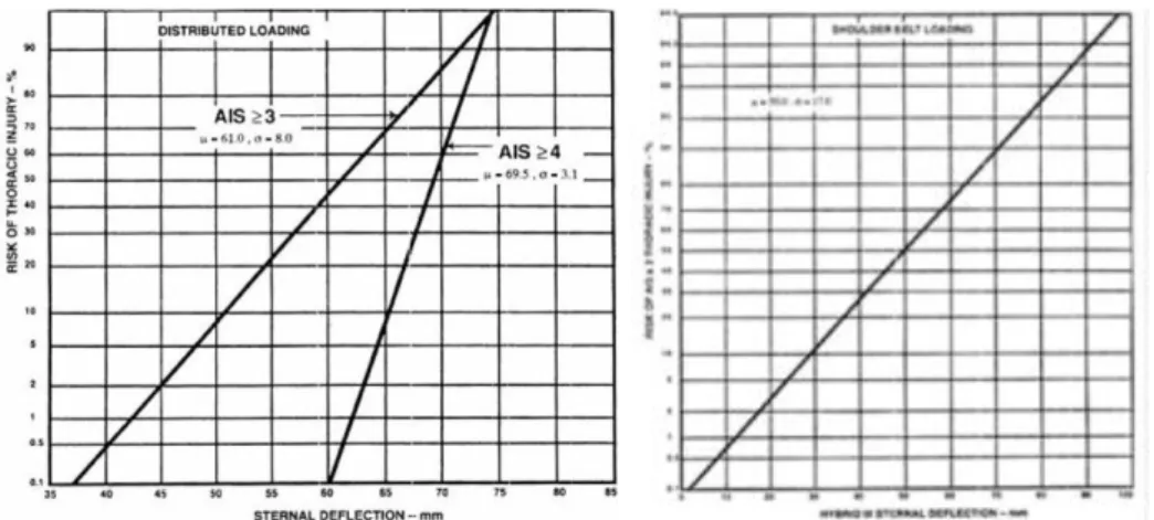
Fig. 19. Risk of thoracic injuries as a function of sternal deflection for a mid-size adult male (left) and as a function of Hybrid III sternal deflection (right) (Mertz et al.,
1991)... 47
Fig. 20. Risk curve for AIS≥4 chest injury based on Viscous Criterion for blunt frontal
impact (Lau and Viano, 1986)... 48
Fig. 21. Illustration of the Combined deflection on a deformed thorax (Song et al.,
2010)... 50
Fig. 22. Chest compression during relaxed (left) and braced (right) conditions (Kemper et al. 2011). ... 52
Fig. 23. Ratios for age changes in the ultimate tensile strength of soft tissues (Yamada,
1970)... 54
Fig. 24. Age-related change in rib slope (Gayzik et al., 2008; Kent et al., 2003). ... 55 Fig. 25. Illustration of mechanism by which increased rib angle increases thoracic
stiffness while decreasing chest deflection tolerance (Kent et al., 2005). ... 55
Fig. 26. Overview of the HUMOS2 scaling tool (Vezin and Verriest, 2005). ... 60 Fig. 27. Sled configuration based upon a standard sedan car environment of a front
passenger restrained by a 3-point belt. ... 68
Fig. 28. Comparison of sled pulses applied in vivo. ... 69 Fig. 29. Distribution of tested subjects compared to the initial targets based upon
anthropometry charts (Jürgens et al., 1990). ... 70
Fig. 30. Landmarks spread over volunteer during belt loading. ... 72 Fig. 31. Overview of camera location and field of view. ... 72 Fig. 32. Reconstruction of an object in space from the images taken by several cameras.
Adapted from (Compigne et al., 2004). ... 73
Fig. 33. Calibration of the sled scene with the calibration object. ... 73 Fig. 34. Comparison of different methods of interpolations of mid-sternum landmark
trajectory for the computation of mid-sternum deflection. ... 74
Fig. 36. Computation of the resulting shoulder belt load FRes (adapted from Eickhoff et
al., 2011). ... 76
Fig. 37. Standard deviation ellipse on force-deflection curve (adapted from Shaw et al., 2006)... 77
Fig. 38. Definition of Dynamic Stiffness (DS) and Effective Stiffness (ES) on experimental force-deflection curve... 78
Fig. 39. Comparison of mid-sternum compression corridors for 50th percentile male from the present study (n=3) and Kemper et al. (2011; n=5). ... 80
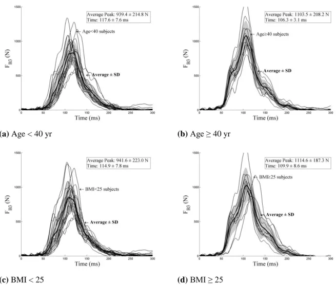
Fig. 40. Time history of the external shoulder belt force FB3 for age group and BMI group... 84
Fig. 41. Time history of the lower shoulder belt force FB4 for age group and BMI group... 85
Fig. 42. Time history of the lap belt force FB6 for age group and BMI group. ... 85
Fig. 43. Time history of the resultant shoulder belt force FRes for age group and BMI. ... 86
Fig. 44. Time history of mid-sternum compressions for different age and BMI groups. ... 87
Fig. 45. Maximum belt loads for different age and BMI groups. ... 87
Fig. 46. Maximum compression for different age and BMI groups. ... 88
Fig. 47. Comparison of sternal relative trajectories in sagittal plane for age and BMI group... 89
Fig. 48. Maximum sagittal excursion for different age and BMI groups. ... 89
Fig. 49. Thoracic force-deflection curve for different age and BMI groups. ... 91
Fig. 50. Maximum force-deflection characteristics for different age and BMI groups. ... 91
Fig. 51. Thoracic force-deflection curve computed from model parameters for different age and BMI groups. ... 92
Fig. 52. Correlation of K,μ parameters with age and BMI. The coefficient of determination R2 for linear regression was displayed when correlation was found significant (p<0.05). ... 92
Fig. 53. Pareto chart of the percent variability explained by each principal component from PCA. ... 94
Fig. 54. Projection of the variables (blue line) and the subjects (red symbol) against the
selected principal components. ... 95
Fig. 55. Age and BMI group factor maps for the first three principal components. ... 96
Fig. 56. Dendrogram illustrating the arrangement of the clusters produced by AHC. ... 97
Fig. 57. AHC group factor maps for the first three principal components. ... 98
Fig. 58. THUMS features (Toyota Central R&D Labs Inc.). ... 104
Fig. 59. Thorax and spine mesh (Toyota Central R&D Labs Inc.). ... 104
Fig. 60. Synthesis of the personalization process. ... 106
Fig. 61. Segmentation of the 50th percentile male THUMS model. ... 107
Fig. 62. Generation of initial surface nodes of the left forearm ... 107
Fig. 63. Personalization of thoracic surface points by RBF with the 42 thoracic anatomical points... 109
Fig. 64. Definition of thoracic anatomical landmarks for thoracic geometry personalization. ... 109
Fig. 65. Personalization of left arm surface points by homothety with limb length and circumference. ... 110
Fig. 66. Definition of lateral anatomical landmarks used for posture personalization. ... 112
Fig. 67. Rotation of target surface nodes according to volunteer’s posture. ... 112
Fig. 68. Mesh interpolation by RBF using surface nodes. ... 113
Fig. 69. MRI-scans used for the assessment of the thoracic geometrical personalization. .... 114
Fig. 70. View of the distance di found for skin point of the reference geometry CT-scan to the closest point of the personalized thorax mesh using thoracic skin set. ... 115
Fig. 71. Six geometrically personalized FE models. ... 122
Fig. 72. Distribution of tested subjects compared to the initial targets based upon anthropometry charts (Jürgens et al., 1990). ... 123
Fig. 73. Generic interior vehicle model with a personalized THUMS human body model. ... 125
Fig. 74. Low speed (gray) and high speed (black) pulses used for the sled test
simulations. ... 127
Fig. 75. Definition of the points used for chest deflection measurement during
simulation. ... 129
Fig. 76. Prediction of bone fractures in simulation. ... 129 Fig. 77. Comparisons of external shoulder belt load FB3 between geometrically
personalized models and in-vivo sled tests at low speed (4 g, 8 km/h). ... 133
Fig. 78. Comparisons of internal shoulder belt load FB4 between geometrically
personalized models and in-vivo sled tests (4 g, 8 km/h). ... 133
Fig. 79. Comparisons of the lap shoulder belt load FB6 between geometrically
personalized models and in-vivo sled tests (4 g, 8 km/h). ... 134
Fig. 80. Comparisons of the resultant shoulder belt load FRes between geometrically
personalized models and in-vivo sled tests (4 g, 8 km/h). ... 134
Fig. 81. Comparisons of mid-sternum deflections between geometrically personalized
models and in-vivo sled tests (4 g, 8 km/h)... 135
Fig. 82. Comparisons of mid-sternum compression between geometrically personalized models and in-vivo sled tests (4 g, 8 km/h)... 135
Fig. 83. Comparisons of the thoracic forces-deflection responses between geometrically personalized models and volunteers (4 g, 8 km/h). ... 136
Fig. 84. Maximum outputs for different geometrically personalized models. ... 138 Fig. 85. Force-deflection obtained for geometrically personalized models at high speed
(IJ40). ... 140
Fig. 86. Von Mises stress contour obtained for geometrically personalized models in high speed sled tests at maximum bony midsternal deflection time (upper: cortical, lower: cartilage & trabecular). ... 141
Fig. 87. Significant correlations of outputs with the number of fractured ribs. ... 143 Fig. 88. Maximum outputs for different personalized models considering aging. ... 145 Fig. 89. Force-deflection obtained for personalized models considering aging at high
Fig. 90. Von Mises stress contour obtained for personalized models considering aging in high speed sled tests at maximum bony midsternal deflection time (upper:
cortical, lower: cartilage & trabecular). ... 148
Fig. 91. Autochoc, crash simulator of MACIF. ... 174
Fig. 92. Testochoc, crash simulator of French Road Safety. ... 174
Fig. 93. Ifsttar sled. ... 174
Fig. 94. Mean deceleration pulses of the three devices. ... 177
Fig. 95. HIII AM50 (black) and HIII AF 05 (grey) sternal deflection measured by internal dummy sensor (solid lines) and stereovision (dotted lines). ... 177
Fig. 96. Thorax mechanical responses of two volunteers (S01 in grey, S03 in black) overlayed with Dummy ones. (thick lines) ... 177
Fig. 97. Side view of spine kinematics of S01 (left) and S03 (right) subjects relative to the sled. 2D trajectory of T8 is shown in black line. ... 177
Fig. 98. External anthropometric measurements taken on volunteers. ... 184
Fig. 99. Body coordinates system. ... 187
Fig. 100. Anatomie de la cage thoracique (Gray, 1918). ... 195
Fig. 101. Réponses mécaniques du thorax évaluées sur impacteurs (Kroell C.K., 1971) ; (Nahum A.M., 1975; Neathery, 1974). ... 195
Fig. 102. Relèvement costal chez les personnes agées (Gayzik et al., 2008; Kent et al., 2003)... 197
Fig. 103. Vue globale du dispositif. ... 199
Fig. 104. Définition des raideurs thoraciques DS et ES. ... 199
Fig. 105. Comparaison de corridors de compressions pour des volontaires proche du 50ème percentile homme entre cette étude (n=3) et Kemper et al. (2011; n=5). ... 200
Fig. 106. Courbe de force-déflection thoracique pour different groups d’âge et de BMI. .... 200
Fig. 107. Dendrogramme illustrant la répartition des groupes produit par la classification hiérarchique ascendante. ... 201
Fig. 109. Synthèse du processus de personnalisation géométrique. ... 203 Fig. 110. IRM utilisés dans l’évaluation du processus de personnalisation géométrique. .... 204 Fig. 111. Modèles personnalisés géométriquement soumis à un pulse similaire aux
essais invivo ... 206
Fig. 112. Modélisation d’un intérieur générique adapté au modèle THUMS personnalisé géométriquement placé en position passager. ... 206
Fig. 113. Modèles personnalisés géométriquement pour l’étude de l’influence de la
personnalisation géométrique ... 207
Fig. 114. Contraintes d Von Mises stress obtenus pour quatre modèles personnalisés géométriquement soumis à un pulse de 13g à 40 km/h (haut: cortical, bas: cartilage & traveculae) ... 208
LIST OF TABLES
Table 1. Material properties of the cortical bone (Yamada, 1970). ... 31 Table 2. Thoracic tolerance reduction ratio with age at the injury level of AIS3 (Zhou
et al., 1996). ... 35
Table 3. AIS rating for skeletal and soft tissue thoracic injuries (Schmitt et al., 2009). ... 38 Table 4. Key dimensions and weights for various sizes of dummies (Nahum and
Melvin, 2002). ... 43
Table 5. Frontal impact criteria and tolerances for the thorax (Schmitt et al., 2009). ... 51 Table 6. Volunteer studies on thorax mechanical response in antero-posterior loading. ... 53 Table 7. Material property of the cortical rib in an elderly thoracic model based on the
50th percentile male THUMS (Tamura et al., 2005). ... 60
Table 8. Material property of the ribcage for adult and elderly model (Ito et al., 2009). ... 61 Table 9. Overview of recent thorax FE model from (Charpail, 2006; Yang et al., 2006) ... 62 Table 10. Anthropometric characteristics of volunteers subjected to sled tests. ... 70 Table 11. Thoracic mechanical characteristics dataset obtained from in vivo sled tests. ... 81 Table 12. Thoracic mechanical characteristics dataset from in vivo sled tests: different
age and BMI groups. ... 82
Table 13. Reduced thoracic mechanical dataset used for PCA and ACH. ... 93 Table 14. The principal component coefficient for each variable obtained using PCA.
Markers variables are underlined. ... 94
Table 15. AHC group description according to age, genders and BMI groups ... 98 Table 16. AHC group description according to anthropometries. ... 98 Table 17. AHC group description according to markers variables. ... 99 Table 18. Surface nodes extracted for each body part ... 106 Table 19. External anthropometric measurements used in the personalization process. ... 111 Table 20. Results of woman personalized models with different candidate nodes as
Table 21. Optimum set candidate nodes as thoracic palpable points. ... 117 Table 22. Results of man and woman personalization for different combination
candidate nodes as thoracic palpable points on global anthropometry dimensions. ... 118
Table 23. Results of man and woman personalization for different combination
candidate nodes as thoracic palpable points on thoracic anthropometry dimensions. ... 118
Table 24. Results of man and woman personalization for different combination
candidate nodes as thoracic palpable points on weight. ... 119
Table 25. Results of man and woman personalization for different combination
candidate nodes as thoracic palpable points on mesh quality. ... 119
Table 26. Anthropometric characteristics of volunteers subjected to THUMS
personalization process. ... 121
Table 27. Thoracic anthropometries of volunteer 948 and 118 ... 123 Table 28. Ratio for personalization of material properties according to age from Ito et
al. (2009). ... 124
Table 29. Material properties of the initial THUMS model (1) and the aged THUMS
model (2). ... 126
Table 30. Cortical thickness of the initial THUMS model (1) and the aged THUMS
model (2). ... 126
Table 31. Level of material property personalization and associated versions of
personalized THUMS models. ... 126
Table 32. Simulation tests matrix ... 128
Table 33. Computation of Torso Abbreviated Injury Scale (TOAIS) according to the
number of fractured ribs and their location (AIS 2005). ... 130
Table 34. Thoracic mechanical characteristics obtained on geometrically personalized
models and volunteers at low-speed (4g, 8km/h). ... 132
Table 35. Thoracic mechanical characteristics dataset obtained on geometrically
personalized models at high-speed (13g, 40km/h). ... 139
Table 36. Fractures summarize for geometrically personalized models at high speed
Table 37. Computation of Torso Abbreviated Injury Scale (TOAIS) according to the number of fractured ribs and their location for geometrically personalized models
at high speed (IJ40). ... 143
Table 38. Thoracic mechanical characteristics dataset obtained on personalized models considering aging at high-speed (13g, 40km/h). ... 146
Table 39. Fractures summarize for the personalized models considering aging ... 149 Table 40. Computation of Torso Abbreviated Injury Scale (TOAIS) according to the
number of fractured ribs and their location for the personalized models considering aging. ... 150
Table 41. Definition of landmarks acquired on volunteer (front & back) during sled
tests (1/3). ... 179
Table 42. Definition of the anatomical landmarks acquired on left side of the volunteer during sled tests. ... 181
Table 43. Definition of the thorax anatomical landmarks acquired on thorax volunteer
for geometrical personalization process. ... 182
Table 44. Definition of the anatomical landmarks acquired on THUMS geometry. ... 183 Table 45. Definition of the anthropometric measurements taken on volunteers. ... 185 Table 46. Résultats des modèles personnalisés géométriquement pour différents jeux de
INTRODUCTION
Although significant improvements have been achieved in mitigating road traffic fatalities, frontal impacts play a predominant role in the frequency of road traffic fatalities as they account for up to 46% of the mortality (Klanner, 2001). This impact configuration often causes bony fractures mainly in the thoracic region. In particular, several studies have reported that elderly people are susceptible to sustain sternum and rib fractures, thereby, leading to high mortality and morbidity rates (Lafont and Laumon, 2003; Ndiaye and Chiron, 2009).
Yet, age is a global parameter, strongly linked to corpulence and it seems important to define their influence on intrinsic parameters explaining thorax mechanical response in dynamic loading: properties of biological tissues (bone, cartilage), costo-vertebral and costo-chondral joint stiffness and joint limits, thorax morphotypes (spine curvature, rib angle).
Work schedule n° 2 “Thorax vulnerability of elderly car users” project was conducted at Ifsttar in partnership with Toyota Motor Europe. It aimed to quantify the influence of age on thorax mechanical response and its consequences on injury mechanisms in frontal impacts. For that, two steps were defined:
First, to identify the age specificities on thorax mechanical response by performing a in vivo parametric study
Secondly, to show the ability of personalized FE human body model to predict increased injury risk.
First objective of the thesis is to develop and implement an in vivo test protocol to analyse the link between subject intrinsic parameters (gender, age, corpulence, morphology of the thorax) and thorax mechanical response under belt loading. This analysis should answer the following questions:
What are the parameters explaining the thorax mechanical response during an antero-posterior loading?
What is the influence of age genders and BMI on these parameters?
In addition, there are no injury assessment tools accounting for differences in anatomical features and biological material properties that are observed between adults and elderly.
Compare to ATD, human numerical models have the potential to predict local physical variables that can be related to injury. Moreover, they offer a large potential of customization in term of geometry, material and joint properties. Nevertheless, the choice of the level of customization and its sensibility to predict thoracic injury risk is still a scientific obstacle.
Thus, the second objective of the thesis is to use customize FE models to do the same analysis in the injurious domain. For that, first step aims at implementing a geometrical personalisation process in order to adapt the geometry and the posture of a human FE model to various cases. Second is based on simulations in the injurious domain to isolate the role of geometrical parameters possibly linked to the thorax mechanical response under dynamic loading and their role in severity.
In Chapter 1, after some anatomical description of the thorax, thoracic injury mechanisms are summarized. Then, a state of the art of thorax mechanical response in antero-posterior loading and thoracic injury criteria is presented. Their limitations to account for differences in anatomical features and material properties between adults and elderly were listed. Finally, the benefit of in vivo experiments to enlarge the limited amount of available response data and the potential of personalized numerical model to predict personalize risk injury were also presented.
Chapter 2 presents first the in vivo protocol for the analysis of thorax mechanical response under belt loading carried out on adults of various anthropometries and age. Then, the influence of age and overweight on thorax mechanical response is analyzed.
Chapter 3 describes the methodology used to personalize the geometry and posture of the THUMS model using external landmarks and anthropometric dimensions taken on volunteers. The process was assessed on one subject by comparing computed thorax geometry and IRM data and on other subjects by comparing anthropometric dimensions.
Chapter 4 provides the analysis of simulations of personalized models of six specific subjects. First, a validation of the models under a low pulse is presented. Then, simulations of more severe pulse are used to compare different levels of personalization in the injury risk.
CHAPTER I - STATE OF THE ART
1. Anatomy of the human thorax
The human thorax is the upper part trunk between the neck and the abdomen. The thoracic region is bounded above by the shoulder girdle and the first pair of ribs, posteriorly by the thoracic spine and the posterior arch of the ribs, laterally by the ribs and anteriorly by the sterno-costal plastron.
The thoracic segment consists of:
the bony structure of the thorax or ribcage which protects the viscera contained therein,
the musculature and the skin which constitute the outer shell of this segment,
the intra-thoracic viscera (heart, lungs, vessels ...).
1.1 Ribcage
The ribcage is formed by the sternum, twelve pairs of ribs with cartilage and twelve thoracic vertebrae (Fig. 1). The main role of the rib cage is to maintain and protect vital organs and visceral structures.
The ribs are posteriorly attached to the thoracic vertebrae. Anteriorly, the upper seven pairs of ribs are directly fixed to sternum by the mean of an elastic cartilage, the costal cartilage. The 8th, 9th and 10th pairs of ribs join indirectly the sternum with the costal cartilages of the ribs above. The two last (11th and 12th) pairs of ribs, called floating ribs, are attached to the posterior abdominal wall muscles.
1.1.1 Sternum
The sternum is a symmetrical long flat bony plate where the ribs are attached. Although it is fused, the sternum consists of three main parts: manubrium, body of sternum and xiphoid process. The sternal angle is located at the point where the body joins the manubrium. While manubrium and the body are constituted of bone, the xiphoid process is cartilaginous for youth, but more or less ossified for the adult.
1.1.2 Costal cartilages
The costal cartilages are bars of hyaline cartilage that connect ribs 1-10 to the sternum (either directly for the true ribs or indirectly for the false ribs). The junction between costal cartilage and rib is termed the costo-chondral junction. All costo-chondral junctions are hyaline cartilage joints which firmly bind the rib to the cartilage via continuity of the perichondium (the fibrous outer layer of the cartilage) with the periosteum (the fibrous outer layer of the rib bone). No relative motion occurs between the rib and the cartilage at the costo-chondral junction (Moore and Dalley 1999). The junctions between costal cartilage and sternum are called the sterno-costal junctions. The sterno-costal junction of the first rib consists of a primary cartilaginous joint which do not allow motion between the cartilage and the manubrium (Forman, 2010). The sterno-costal junctions of the second through seventh ribs consist of synovial joints which allow some relative rotation between the cartilage and the sternum during respiration (Moore and Dalley 1999).
During the inspiration, the elevation of ribs leads the costal cartilages to undergo a movement of rotation relatively to the sternum (chondrosternal joint) and torsion around their longitudinal axis. The energy expended on the inspiration is stored by the cartilages thanks to their elastic deformation. At the time of muscle relaxation, the cartilages via their elasticity take part in the return of thorax to its initial position (Kapandji, 2009).
The costal cartilages contribute very materially to the elasticity of the walls of the thorax especially the perichondrium, that surrounds the costal cartilage (Forman, 2010).
Limited studies have investigated the material properties of the costal cartilage. Yamada et al. (1970) provided a Young's moduli of costal cartilage of 26 MPa often used in simulation (Yamada, 1970). Nevertheless, Yamada found a strain-softening in tension and a greater stiffness in compression, contrary to nearly all other data available on the mechanical behaviors of hyaline cartilages (Forman, 2010). These differences are likely due to a difference in test methods, and it is difficult to resolve these differences due to the absence of a test method description in Yamada reference (Forman, 2010).
1.1.3 Rib anatomy
The rib is described as elastic flat and long bone with two faces (internal / external) and two edges (top / bottom), and with three curvatures in space:
A curvature along the faces: a medially concave curvature with two bends which are called posterior angle (costal angle) and anterior angle.
A curvature along the edges: it gives the appearance of an S-shape with a back end and one end rose ventral plunging.
A curvature along the axis: it corresponds to the torsion on the rib, and explains that the side of the dorsal segment of the rib is directed downward and backward, while that of the ventral segment is oriented upward and forward.
The rib consists of three parts:
The posterior or vertebral extremity: it consists of a head, a neck and a tuberosity. The head is composed of two facet joints that come to articulate with the thoracic vertebrae. The tubercle is protruding rib back; its articular surface meets the articular surface of the transverse process of thoracic vertebra of same number.
The body is the main part of the rib that takes origin in the tubercle, follows the direction of the neck on a short ride, then bent inwards, forming the costal angle. The body is flattened from within.
The ventral or anterior extremity: it consists of an excavation that receives the outer end of costal cartilage (costo-chondral junction).
Fig. 2. The parts of the rib (Gray, 1918).
The body of the rib is made of highly vascular trabecular (or "spongy") bone (with interstitial bone marrow), surrounded by a thin outer layer of dense cortical bone (Fig. 3). It was found that the distribution of cortical bone was non-uniform and the geometry of cross section very variable as showed in Fig. 3 (Mohr et al., 2007).
a) Cross-sectional view of rib body from a μCT scan (Forman, 2010)
b) Variation of rib cross-section along the longitudinal axis (Mohr et al., 2007).
Fig. 3. Internal structure of the rib.
Cortical bone consists of layers of an arrangement of cylindrical structures called osteons. It is composed of mineral salts (for about 60% by mass), water (25%) and collagen. This structure is heterogeneous, anisotropic and viscoelastic. Young's modulus varies from 15000 to 35000 MPa (Burstein et al., 1976; Yamada, 1970). The behaviour of compact bone is different in tension and compression. Although it has a lower modulus of elasticity in compression than in tension, the ultimate stress and strain at failure are greater for a bone subjected to compression (Cowin, 2001). This observation suggests that the breaking of the compact bone is determined
by its ability to withstand tensile loading (Charpail, 2006). Some material properties of the cortical bone are given in Table 1.
Table 1. Material properties of the cortical bone (Yamada, 1970). σfailure in traction (MPa) εfailure in traction (%) σfailure in compression (MPa) εfailure in compression (%) σfailure in flexion (MPa) 109 1.35 162 1.8 160
Trabecular bone is composed of bone (or trabeculae) and marrow. Its structure has an important role in terms of damping due to the bone marrow that contains therein (Charpail, 2006). It is heterogeneous, viscoelastic and anisotropic. The tranbecular bone may be considered as a material having an elastic phase, a phase of compaction in compression and a damage phase in tension. Its mechanical behaviour is very sensitive to the shear rate: the modulus of elasticity increases with the strain rate (Charpail, 2006). Density also plays an important role on the behaviour (Charpail, 2006). Young's modulus varies from 1.4 to 9800 MPa and the failure stress varies from 0.2 to 25 MPa (Charpail, 2006).
1.1.4 Thoracic vertebrae
Thoracic vertebrae known also as dorsal vertebrae compose the middle segment of the vertebral column, between the cervical vertebrae and the lumbar vertebrae. They are each composed of a vertebral body, two transverse apophyses and a spinous process (Fig. 4). The twelve thoracic bones and their transverse processes have surfaces that articulate with the ribs.
Laterally, the vertebral bodies contain, mostly two facet joints, each of which constitutes half of an articular surface for articulation with the head of a rib. Some rotation can occur between the thoracic vertebrae, but their connection with the rib cage prevents much flexion or other excursion. In this manuscript, we designate the thoracic vertebrae with the letter T followed by the number of the vertebra: for example T7 symbolizes the thoracic vertebra number 7.
a) Inferior view b) Lateral view
1.1.5 Costovertebral joints
On each level of the thoracic spine, a pair of ribs articulates with the vertebrae by two joints:
the costovertebral joint between the rib head and the intervertebral disc and the vertebral bodies.
the costo-transverse joint between the rib tubercle and the transverse process of the underlying vertebra.
Kapandji hypothesizes that the costovertebral joint, on the one hand, and the costo-transverse joint, on the other hand, are mechanically linked (Kapandji, 2009). Their combined movement during breathing is a rotation around a common axis passing through the center of each of these two joints (Fig. 5). For the lower ribs, this axis is closer to the sagittal plane (a), consequently the thoracic cavity space increases along the transversal axis during rib elevation. For the upper ribs, the axis coincides with the frontal plane (b) which increasing the thoracic cavity space along the anterior-posterior direction. In the case of a frontal quasi-static loading of the ribcage, it has been showed that this axis of rotation migrates to remain parallel to the direction imposed (Eckert et al., 2000).
During inspiration, the elevation of the ribs implies the rotational movement of the costal cartilage relatively to the sternum (chondro-sternal joint) and torsion about the longitudinal axis. The costal cartilage stores potential energy due to the inspiration and releases it, to return to its original position during expiration.
1.2 Intercostal muscles
Ribs are interconnected by the intercostal muscle group, forming a solid but flexible barrier between the ribs (Fig. 6). Intercostal muscles are:
external intercostal muscles are attached from the lower border of one rib to the upper border of the rib immediately below, with their fibers orientated obliquely forward and downward. During the inspiration, the external intercostal muscles are tensed in order to produce an upward movement of the anterior thorax;
internal intercostal muscles are attached similarly but their fibers are orientated obliquely backward and downward. The tensing of the internal intercostal muscles results in the outward movement of the anterior thorax, contributing to the expiration.
Fig. 6. Intercostal muscles (Gray, 1918).
1.3 Viscera
The ribcage protects vital organs from injuries involved in respiration and blood circulation. Thoracic cavity can be divided into three cavities:
the right and the left outer cavities contain the lungs. Each lung is surrounded by a thin membrane called visceral pleura. The entire volume of the rib cage is covered by another thin membrane, the parietal pleura.
the center cavity, called mediastinum, contains the heart, the esophagus, the trachea and large vessels.
Fig. 7. Anatomy of pleural cavity and mediastinum (Gray, 1918).
2. Thoracic trauma in frontal impact
2.1 Abbreviated Injury Scale (AIS)
Traumatic injuries referencing and severity are performed with the Abbreviated Injury Scale (AIS). The AIS was developed to provide to researchers a simple numerical method for ranking and comparing injuries by severity and to standardize the terminology describing the lesions.The values of AIS quantify injuries and not their consequences. AIS can be used as an intrinsic ²evaluation of the severity of the injury and not as a measure of disability that may result.
At the end of this section, Table 3 provides an overview of different injuries and their according AIS.
2.2 Accidentology
Various parts of the vehicle interior (like the steering wheel, safety belt, or the dashboard) can be in contact with the thorax in frontal collisions. In these conditions, sharp impact to the thorax is rare, occurring only due to obstacles inside or when the occupant is ejected from the vehicle. Consequently, most thorax injuries caused by contact mechanisms are caused by blunt impact.
Statistics showed that thoracic injuries were the main source of serious casualties of elderly ones (Lafont and Laumon, 2003). Considering AIS≥2 thoracic injuries in the elderly population, it was observed that it was mainly rib and sternum fractures as showed in Fig. 8 (Ndiaye and Chiron, 2009).
Fig. 8. Type of thoracic injuries AIS≥2 by genders and age (Ndiaye and Chiron, 2009).
It is well established that tolerance of the human thorax under dynamic loading decreases as age increases (Zhou et al., 1996). Using, the published data of PMHS tests under 3-point belt, the injury severity of each age group was assessed by the mean number of thoracic fractures normalized by the value of the 20-29 age group. Under same loading conditions, the injury severity increases substantially as age increases. From these results, it was assumed that the number of rib fractures increases linearly by approximately 0.33 rib fracture per year based on age at the time of death (Petitjean et al., 2003). By using the number of fractured ribs of the young group as a standard, Table 2 synthetises the recommended reduction ratios at the injury level of AIS3.
Table 2. Thoracic tolerance reduction ratio with age at the injury level of AIS3 (Zhou et al., 1996).
Age range 16-35 36-65 66-85
Reduction ratio 1 0.47 0.28
Three different injury mechanisms can be occurred when the thorax is injured in blunt impact: compression, viscous loading and inertia loading of the internal organs. Furthermore any combination of these three basic phenomena can occur (Schmitt et al., 2009).
The resulting injuries can be categorized as skeletal injuries and soft tissue injuries. Most often the thoracic wall and the lung are injured together with rib fractures, sternum fractures and pleura ruptures. American epidemiological studies have highlighted that internal thoracic
0% 10% 20% 30% 40% 50% 60% 70% 80% 90% 100%
Young WomenOld Women Young Men Old Men
Rib fracture with or without
hemo/pneumothorax Flail chest
Internal/vessels Whole area (crush)
vital organ injuries are relatively infrequent in 3-point belt restrained victims in frontal collisions (Yoganandan et al., 1991).
2.3 Thoracic injuries mechanisms
2.3.1 Rib fractures
The rib fracture is the complete rupture of one or more ribs. The fracture can be closed if the skin and the soft tissue overlaying the fracture remain intact or open if the chest wall is perforated by sharp edges of broken ribs. In less serious cases, the rib fracture is self-healing and causes localized pain, discomfort during breathing and sleeping.
However, when the chest wall is perforated by sharp edges of broken ribs, life threatening complications may appear. In particular, when multi rib fractures occurred, a portion of the chest wall is released from the entire skeleton. These phenomena called flail chest makes it difficult to expel the air out of the lung.
Generally, sagittal loading of the ribcage is more likely to cause single rib fracture, while lateral impact more often results in multi rib fractures. Rib fracture occurs at the maximum point of curvature or at the location where a force is applied. As the ribs have a stronger curvature in the lateral part with less soft tissues that cover the ribs, lateral fractures are more usual.
The site of lateral rib fractures depends on the shape of the impacting body (Fig. 9). According to PMHS studies (Melvin et al., 1975; Stalnaker and Mohan, 1974), the number of rib fractures depends on the magnitude of rib deflection rather than on the rate of deflection. However, due to the viscous nature of the thorax, the maximal force depends on the loading rate. Maximal force appears to be related to the number of rib fractures for a given loading rate.
2.3.2 Lung injuries
The most frequent lung injuries are lung contusions. Lung contusions appeared with excessive thorax compression. This often happens with combination with flail chest but can occur without any rib fracture. Unlike bone fractures, lung contusion is rate-dependent (Fung and Yen, 1984). At high velocities, a shock wave is transmitted to the lung tissue and can cause microscopic ruptures of vessels.
However, the laceration and lung perforation traumatisms caused by fractured ribs are more critical to life (Schmitt et al., 2009). This may result in a pneumothorax or a hemothorax. The pneumothorax is an abnormal presence of air in the pleural cavity which is due to the perforations of the pleura and the lung producing a loss of air from the lung tissue to the pleural cavity. During the inspiration, the pleural cavity fills with air whereas during the expiration, the laceration in the lung tissue is compressed preventing the air in the pleural cavity to be expelled. Therefore, the lung progressively deflates. The hemothorax is an accumulation of blood in the pleural cavity due to bleeding injuries in the thorax, e.g. lacerations of blood vessels running between the intercostal muscle layers in each intercostal space. As blood is incompressible, the volume in which the lung can expand is reduced.
2.3.3 Other injuries
The space between the sternum and the thoracic vertebrae is particularly minimal, thus the compression of the anterior chest wall can cause the direct traumatic impact of the sternum with internal anatomical components or the displacement and the possible tearing of the mediastinum structures. A significant thorax deceleration results in a difference in kinetic energy between the mediastinum components which is responsible for shearing, tearing or impact of the organ tissues (Schmitt et al., 2009).
In case of frontal collision implying thoracic impact, the heart can be subjected to several injuries including contusion and laceration (Fig. 10). Contusions appear with heart crushing on the anterior face of the sternum. The lacerations of the pericardial sac, which enclosed the heart, are caused by broken part of the bony structure. Likewise, the perforation of the heart can arise in case of high thoracic compression magnitude. Another life threatening complication due to a thoracic impact at high velocity is a disorder of the heart electric conduction bringing about a cardiac fibrillation or even a cardiac arrest (Schmitt et al., 2009).
Furthermore, major thoracic blood vessels like the aorta can be injured. Rupture and laceration are the most likely mechanisms resulting front blunt impact trauma to the thorax.
Cavanaugh reports that arterial injury account for 6% to 8% of AIS>2 only, but represent 30% of the estimated harm (Cavanaugh, 1993). It should be noticed that the majority of the victims sustaining an aortic trauma die at the scene of the accident.
Fig. 10. Compression of the heart (Schmitt et al., 2009).
The most vulnerable aortic region is located at the junction of the aortic arch and the descending thoracic aorta (Creasy et al., 1997). The rupture or the light fissure of this anatomical part occurs either from the traction or the shearing generated between a movable group composed by the heart and the aortic arch, and the immovable descending portion of the aorta which is joined to the thoracic wall, or simply due to the direct compression over the vertebral column. An excessive sudden increase of the intraluminal pressure is also a possible injury mechanism.
Table 3. AIS rating for skeletal and soft tissue thoracic injuries (Schmitt et al., 2009). AIS Injury severity Skeletal injury Soft tissue injury
1 Minor 1 rib fracture Contusion of bronchus
2 Moderate 2-3 rib fractures
Sternum fracture Partial thickness bronchus tear
3 Serious
4 or more rib fracture on one side 2-3 rib fractures with
hemo/pneumothorax
Lung contusion Minor heart contusion
4 Severe
Flail chest
4 or more rib fractures on each side
4 or more rib fractures with hemo/pneumothorax
Bilateral lung laceration Minor aortic laceration
Major heart contusion
5 Critical Bilateral flail chest
Major aortic laceration Lung laceration with tension
pneumothorax
6 Untreatable Aortic laceration with haemorrhage
3. Thorax mechanical response during frontal loading
3.1 Blunt impact tests
Numerous tests with different configurations were conducted in laboratory on PMHS to assess thorax biomechanical response in frontal impacts. First understanding of thoracic biomechanical response to antero-posterior loading was assessed in the past on Post Mortem Human Surrogates (PMHS) using blunt hub impactor tests (Kroell C.K., 1971; Lobdell et al., 1973; Nahum A.M., 1975; Neathery, 1974). These blunt impact tests were representative simulations of the impact from the steering wheel to an unrestrained occupant (due to the low rates of seatbelt use in the 1960’s and 1970’s).
PMHS were subjected to dynamic, antero-posterior blunt loading of the thorax, involving a 15 cm diameter circular rigid impactor (Kroell C.K., 1971). The impact was accomplished by an impacting mass travelling at constant velocity (4.3 m/s - 10 m/s) in the horizontal direction and striking the thorax of an upright-seated surrogate (Fig. 11).
Fig. 11. Thoracic mechanical responses on PMHS using impactor (Kroell C.K., 1971; Nahum A.M., 1975; Neathery, 1974).
Corridors were formed by bounding the individual force-deflection responses at several impact velocities in order to illustrate the rate-related changes in thorax behaviour (Neathery, 1974). These corridor responses were used for the validation standard Hybrid III dummies (Schneider et al., 1989).
3.2 Compression tests
Several authors carried out series of PMHS positioned supine on a table and subjected to a seatbelt-like loading as described in Fig. 12 (Cesari and Bouquet, 1990; Kent et al., 2004; L’Abbe et al., 1982). The analysis of thoracic deflection showed that the most extensive deformations is situated at the point 8 which is on a relatively soft part of the thorax, as well
as at the point 1 which is more deflected than the two other points on the sternum. Moreover, these results strongly support the fact that the lower region of the human thorax is more compliant than the upper region, because of changes in the overall geometry and individual rib geometry.
Fig. 12. Supine belt loading setup and instrumentation (Cesari and Bouquet, 1990).
In compression tests, the thorax is loaded between the table and the belt. The advantage of this protocol is to provide a fixed reference plane in the analysis of the thorax deformation. The authors support the idea that the interactions between the ribs and the table have a negligible effect on the thoracic deflection. The main limitation of the compression tests is the possible restriction of rib rotation due to the supine position. This could virtually increase the thoracic stiffness due to constraints in costovertebral joints. In this test configuration, the subject is put in a different situation than that of a belted car occupant in a frontal collision where the belt loading is only due to the occupant inertia.
3.3 Sled tests
In sled test, forward motion of the subject is stopped by the belt like in real-world crashes (Fig. 13). In the 1990's, sled tests were carried out on PMHS in order to quantify thoracic deformations in simulated frontal impacts with several kinds of restraint system (Crandall et al., 1994; Kallieris et al., 1995; Kallieris et al., 1994; Yoganandan et al., 1993; Yoganandan et al., 1991). Fig. 14 illustrates the typical belt force-time histories obtained during sled tests in which the subject was restrained by a standard 3-point belt (Kallieris et al., 1994; Yoganandan et al., 1991). In addition, the pattern of thoracic deformation contours obtained from Chestband indicated considerable local compressions of the thorax at the belt path (Fig. 14).
Fig. 13. Sled tests on PMHS with belt restraint system in a real world crash environment (Kuppa and Eppinger, 1998).
Fig. 14. Typical force-time histories (left, center) and chest contours (right) of a driver restrained by belt or airbag in frontal impact (Kallieris et al., 1994; Yoganandan et al., 1991).
In this configuration, the most common thorax injuries were fractures, especially rib fractures. The thoracic injury severity seems to be influenced by the age of the occupant, the impact severity and the restraint condition. The type of restraint system used causes specific patterns of rib fractures, whereas the number of rib fractures seems to vary depending on both the subject's age and the impact velocity (Fig. 15).
Fig. 15. Examples of injury pattern in sled tests by using 3-point belt and airbag (Kallieris et al., 1994).
3.4 Influence of loading conditions
Although blunt impact tests allowed the increase in the understanding of the thorax behavior, the current automotive environment is different than the environment when the hub impact tests were being conducted. In particular, injuries from belt or air bag loading are becoming more important as their uses are standard in recent vehicles (Kent et al., 2003).
Kent et al. conducted several PMHS tests, with different protocols (Kent et al., 2004). The human cadavers were subjected to four loading conditions on the anterior thorax (single belt loading, double belt loading, distributed loading and hub loading). He demonstrated that the calculated effective stiffness of the thorax is strongly dependent on the load distribution. The distributed loading condition generates the highest effective stiffness whereas the hub load generates a lower effective stiffness than the other conditions.
Fig. 16. Force at 20% chest deflection for a 50th male as a function of loaded area (Kent et al., 2004).
The force required to generate an injurious level of deflection is strongly dependent on the load distribution on the thorax (Kent et al., 2004). Thus, corridors defined using impactors should not be used to assess thorax mechanical response under belt loading.
4. Thoracic injury assessment based on dummy responses
Anthropomorphic test devices (ATD), commonly termed crash test dummies are mechanical surrogates of the human body that simulate its dimensions, weight proportions and joints (Mertz, 1993). They are used in the field of transport safety to assess the injury risk and thus to assess the effectiveness of various restrains systems and car designs. ATD are instrumented with transducers that measure accelerations, deformations and loads of main body parts. These measurements are analyzed to compute specific injury criteria that are link to injury risk.
4.1 Anthropomorphic test devices
ATD are classified according to size, age, sex and impact direction. The midsize adult male dummy is the most utilized size in automotive restrain testing. It approximates the median height and weight of the 50th percentile adult male population. The height and weights of the small female and large male adult dummies are approximately those of the North American 5th percentile female and the North American 95th percentile male respectively. Key dimensions and weights for various sizes of dummies are given in Table 4.
Table 4. Key dimensions and weights for various sizes of dummies (Nahum and Melvin, 2002). Key dimensions and
weights
Infants Children Adults (percentile)
6 mo 12 mo 18 mo 3 yr 6 yr 5 th female 50th male 95th male Dimensions (mm)
Erect sitting height 439 480 505 546 635 812 907 970
Buttocks to knee 170 198 221 284 381 521 589 638 Knee to floor 125 155 173 221 358 464 544 594 Shoulder to elbow 130 150 160 193 234 305 366 381 Elbow to fingertip 175 198 213 254 310 399 465 503 Standing height 671 747 813 953 1168 1510 1751 1873 Weights (kg) Head 2.11 2.49 2.72 3.05 3.48 3.68 4.54 4.96 Neck 0.29 0.34 0.35 0.43 0.41 0.81 1.54 2.04 Torso 3.04 4.38 5.22 6.61 10.76 24.14 40.23 53.00 Upper extremity 0.85 1.18 1.31 1.79 1.98 4.67 8.53 10.94 Lower extremity 1.53 1.31 1.60 2.63 4.28 13.52 23.36 31.79 Total weight 7.82 9.70 11.20 14.51 20.91 46.82 78.20 102.73
The first crash test dummy used by the domestic automobile industry for restraint was Sierra Sam, a 95th percentile adult male dummy that was developed by Sierra Engineering in 1949 for ejection seat testing by the U.S. Air Force (Mertz, 1993). The most used of the early frontal impact dummies was the Hybrid II midsize adult male dummy, developed by General Motors in 1972 to assess 3-point belt systems. In addition to midsize male, small adult female and large adult male were developed. Hybrid II dummy family was known to have lack in head and neck biofidelity and had little instrumentation (Nahum and Melvin, 2002).
Hybrid III dummy family was developed to improve the biofidelity and instrumentation drawbacks of the Hybrid II family (Mertz, 1993). These dummies consist of a small adult (5th percentile) female adult, a midsize adult (50th percentile) male dummy, a large adult (95th percentile) male dummy and a 3-year-old and a 6-year-old child dummy. The midsize male dummy which made its first appearance in 1976, is the standard crash test dummy in frontal impact. Hybrid III are limited in their biofidelity and in their application type. Indeed, the
Hybrid III chest is two times stiffer than the thorax of PMHS (Cesari and Bouquet, 1994). In addition, the Hybrid III dummy does not adequately assess the risk thoracic lesion (Foret Bruno et al., 1998). It comes in contradiction with the accidentology in the evaluation of the restraint belt with force limiter 4 kN and airbag (Petitjean et al., 2002). Similarly, crash test dummies which are extremely simplified depiction of human anatomy cannot take into account physiology.
Hybrid IIIs are designed to research the effects of frontal impacts, and are less valuable in assessing the effects of other sorts of impacts, such as side impacts. The SID (Side Impact Dummy) family of test dummies has been designed to measure rib, spine, and internal organ effects in side collisions. An international consortium was established to oversee the development of a universal side impact dummy termed WorldSID (Moss et al., 2000).
The successor of Hybrid III dummy, THOR (Test device for Human Occupant Restraint) has been developed to become the successor of Hybrid III dummy. This development program, undertaken by GESAC Inc. in 1995 and oversee by National Highway Traffic Safety Administration (NHTSA), resulted in the design and development of an advanced frontal crash test dummy that incorporates improved biofidelity and significantly expanded instrumentation (Shams et al., 2005). Other companies had recently started developing their own version of the THOR dummy.
4.2 Thoracic injury criteria
An injury criterion is defined as a physical parameter (acceleration, force, penetration) or a function of several physical parameters which correlates well with the injury severity of a body region for a specific type of lesion. Injury criteria are measurable engineering parameters which have the highest injury predictive ability among all others.
Injury risk curves are used to define the injury risk for a given human body response. They are mostly based on data from tests using animals, Post Mortem Human Surrogates (PMHS) or human volunteers. Examples of risk curves are shown in Fig. 17. The injury criterion is presented along the horizontal axis, while the injury risk is presented along the vertical axis. It should be noted that depending on the shape (which is related to the mathematical method used) of the risk curve, a small difference for the injury criterion value could result in large differences for the injury risk.
A protection criterion is defined as a threshold value of the criterion which is associated with a chosen percentage of the risk of sustaining injury.
In the following part, the thorax injury criteria used in automotive regulations are described, along with the emerging criteria proposed for future standards. A synthesis is given in Table 5.
Fig. 17. Examples of injury risk curves for different severities.
4.2.1 Acceleration
In the U.S., the earliest chest injury criterion to enter a crash test regulation which was specified in the Federal Motor Vehicle Safety Standards (FMVSS) 208 was the whole body deceleration tolerance criterion. Mertz and Gadd recommended that the peak chest acceleration measured at the mass centre of the chest does not exceed the value of 60 g for acceleration pulses of 100 ms and shorter, in order to avoid severe thorax injuries (Mertz and Gadd, 1971). Nowadays, the FMVSS 208 injury criteria specify that the 3-ms clip value of resultant chest acceleration at the gravity centre of the upper thorax of the Hybrid III dummy should be limited to 60 g in 48-km/h frontal impact tests against a rigid barrier.
4.2.2 Force
Foret-Bruno studied the possible relationship between the risk of injury and the force applied by the belt to the shoulder (Foret-Bruno et al., 1998). They examined the statistics of 256 car accidents in frontal impact including the textile load limiters and 6 kN limiters. The analysis of the limiter value in relation to the occupant injuries led to the thoracic injury risk curves according to age as function of the shoulder belt force (Fig. 18).
0% 25% 50% 75% 100% 0 1 2 3 4 5 6 Inj ur y ri sk Injury criterion "AIS 2" "AIS 3" "AIS 4"
Tolerance 50 %
risk AIS 3
Fig. 18. Probability of AIS≥3 thoracic injury versus age and shoulder belt load (Foret-Bruno et al., 1998).
In addition, a statistical model was developed from these injury risk curve correlating the risk of severe injury (AIS3+) with the effort in the shoulder and the age:
Equation I-1
4.2.3 Compression criterion
Chest compression C is defined as the chest deformation divided by the initial thickness of the thorax. Analysing blunt impact tests, Kroell concluded that the maximum chest compression correlated well with AIS (Kroell C.K., 1971). The following relationship was established:
Equation I-2
Compressions of 30% and 40% correspond respectively to a thorax injury rated AIS2 and AIS4. A compression of 40% represents 92 mm of chest deflection on a 50th percentile male thorax (229 mm) likely cause multiple skeletal injury, especially flail chest (Fig. 19). A tolerated maximum compression of 33% corresponding to a 50% probability of an AIS≥3 thoracic injury was extrapolated in the 50th percentile male Hybrid III dummy to be a maximum allowable sternal deflection of 75 mm (represented for a 45 year old male in blunt frontal impact). Mertz developed thoracic injury risk curves, for AIS≥3 thoracic injury on the basis of the sternal deflection responses of the Hybrid III 50th adult male dummy restrained by a 3-point belt load system (Mertz et al., 1991).