HAL Id: hal-02307955
https://hal.inria.fr/hal-02307955
Submitted on 8 Oct 2019
HAL is a multi-disciplinary open access
archive for the deposit and dissemination of sci-entific research documents, whether they are pub-lished or not. The documents may come from teaching and research institutions in France or abroad, or from public or private research centers.
L’archive ouverte pluridisciplinaire HAL, est destinée au dépôt et à la diffusion de documents scientifiques de niveau recherche, publiés ou non, émanant des établissements d’enseignement et de recherche français ou étrangers, des laboratoires publics ou privés.
Cooperation between multiple RPL networks
Brandon Foubert
To cite this version:
Brandon Foubert. Cooperation between multiple RPL networks. Networking and Internet Architec-ture [cs.NI]. 2018. �hal-02307955�
(__((___UFR_de_mathématique_et_d’informatique___))))
(___(*(*(___Université_de_Strasbourg__)))___))
Master of Science in Computer Science
Computer Networks and Embedded Systems
Master’s thesis presented by
Brandon Foubert
Cooperation between multiple
RPL networks
Internship supervised by
Julien Montavont
[email protected]In the
ICube laboratory
TABLE OF CONTENTS
Table of Contents iii
Introduction iv
1 Hosting structure 1
1.1 The ICube laboratory . . . 1
1.2 The computer science research department . . . 1
1.3 The network research group . . . 1
1.4 My assignment . . . 2
2 Scientific context 3 2.1 The internet of things . . . 3
2.1.1 IoT constraints . . . 3
2.1.2 IoT network layer . . . 4
2.2 Routing protocols . . . 5
2.2.1 Distance-vector and link-state protocols . . . 5
2.2.2 Proactive and reactive protocols . . . 6
2.2.3 Hop-by-hop and source routing protocols . . . 6
2.2.4 Routing in the IoT . . . 6
2.3 IPv6 Routing Protocol for LLNs: RPL . . . 7
2.3.1 Basic operations . . . 7
2.3.2 Point-to-multipoint and point-to-point traffic support . . . 9
2.3.3 Objective function . . . 9
2.3.4 Advanced features . . . 10
2.3.5 Instances . . . 10
2.4 Problem statement . . . 11
2.4.1 Border router failure . . . 11
2.4.2 Funneling effect . . . 11
3 State of the Art 13 3.1 Border router redundancy . . . 13
3.2 Multiple sinks . . . 13
3.2.1 Virtual DODAG root . . . 14
3.3 Load balancing . . . 15
4 Contribution: RPL-NAT-LB 16 4.1 Considered IoT scenario . . . 16
4.2 Multiple border routers . . . 16
4.2.2 Virtual DODAG root . . . 17
4.3 Multiple IPv6 prefixes . . . 17
4.3.1 Motivations . . . 17
4.3.2 Network address translation . . . 18
4.4 Load balancing . . . 19 4.4.1 Motivations . . . 19 4.4.2 Prerequisites . . . 20 4.4.3 Explicit redirection . . . 20 5 Experimentation 22 5.1 Implementation . . . 22 5.1.1 Contiki OS . . . 22 5.1.2 Cooja . . . 22 5.1.3 Implementation cost . . . 22 5.2 Experiment setup . . . 23 5.2.1 FIT/IoT-LAB . . . 23 5.2.2 Experimental parameters . . . 23
5.2.3 Network layout and scenario . . . 24
5.3 Results . . . 25
5.3.1 Obtained topology . . . 26
5.3.2 Considered metrics . . . 26
5.3.3 End-to-end packet error rate per node . . . 27
5.3.4 MAC packet error rate per node . . . 27
5.3.5 MAC errors repartition . . . 29
5.3.6 Bandwidth repartition . . . 30
5.3.7 Battery capacity decrease . . . 31
5.3.8 Total transmission of control messages . . . 32
6 Conclusion 35 6.1 Contribution . . . 35 6.2 Discussion . . . 36 6.3 Perspectives . . . 36 6.4 Personal review . . . 36 Bibliography 37
INTRODUCTION
The idea of the Internet of Things (IoT) is to connect multiple objects with wireless commu-nication capabilities so those can share information across the Internet. Those objects face many constraints such as reduced storage memory, limited computation power and scarce energy. Due to those constraints, a dedicated computer networking protocol suite is needed. Those protocols must stay efficient even under unfriendly environment conditions such as bad link quality or interference. The Institute of Electrical and Electronics Engineers (IEEE) and Internet Engineering Task Force (IETF) organisms proposed a new network stack composed of new protocols specialized for IoT devices. Especially, the proposed protocol for the net-work layer is the IPv6 protocol, because it offers connectivity with many other devices as well as excellent scalability. While native IPv6 can be used in IoT networks, it is inefficient as it is, and protocols modifications are required in order to make it adequate. Particularly, the proposed de facto routing protocol for IoT networks is the Routing Protocol for Low power and lossy networks (RPL). RPL builds a Direction Oriented Directed Acyclic Graph (DODAG) rooted at one node. This node is known as the root, and in the case of IoT it generally is a border router which acts as a gateway to the Internet.
Because of the way RPL operates, it may suffer from inherent issues. As the border router relays all the traffic between the IoT network and the Internet, it is a single point of failure.Upon border router failure, all nodes depending on it may lose global connectivity with the Internet. Moreover, nodes close to the root must forward traffic from farther nodes in addition to their own, which may cause heavy congestion as well as energy depletion inequality. This is known as the funneling effect, and may lead to severe underachievement such as network partition. Border router failure and the funneling effect may heavily impact the quality of communication in IoT networks. Hinted by the RPL specification, border router redundancy could be a solution to both issues. However, there is currently no standard mechanism specified.
Hence, the purpose of this master’s thesis is to specify a full solution to enable border router redundancy. To achieve this, we propose a mechanism leveraging cooperation between colocated RPL networks, allowing failover upon border router failure and load balancing. It is introduced thoroughly in the rest of this document along with the results from experiments on real hardware.
Thesis Outline
In this thesis, we will first present the hosting laboratory and research group into which the internship had been conducted. Secondly, we will introduce the IoT as well as RPL and what issues it faces. Thirdly, we will review existing related work among the scientific literature. Then, we will detail our proposal, followed by the results obtained from experimentation. To conclude, we will discuss the conducted work and the potential future research.
CHAPTER
1
HOSTING STRUCTURE
This chapter first introduces the ICube laboratory, which was the internship hosting struc-ture. Then we will move onto the layout of the hosting research group and the internship assignments.
1.1
The ICube laboratory
The ICube laboratory [1] is one of the biggest research force in France. Directed by professor Michel de Matelin, it is split into seven distinct lab locations in the cities of the Strasbourg euro-metropolis and Illkirch-Graffenstaden. It is a mixed research unit between the Stras-bourg University and the French National Center for Scientific Research (CNRS). Created in 2013, it actually hosts around 650 members. Regrouped under the common theme of engineering sciences, this research force is divided into four departments, which in turn are subdivided in groups. Illustrated on the organization chart in Figure 1.1, those four research departments are:
• the computer science department
• the imaging, robotics, remote sensing and biomedical department • the solid-state electronics, systems and photonics department • the department of mechanics
1.2
The computer science research department
The computer science department is directed by professor Pierre Gan¸carski and is composed of 6 research groups out of the 16 groups of the whole laboratory. Each one is specialized in certain fields of computer science, and works on various subjects such as computer graphics and geometry, bioinformatics, data science or computer networks.
1.3
The network research group
The network research group [2] directed by professor Thomas No¨el is part of the computer science department. It hosts several professors and associate professors, a CNRS researcher and an engineer, as well as PhD students and interns. The network group main research topics are the Internet of Things (IoT) and core networks. The group is also involved in several research projects (e.g. Future Internet of Things [3]).
Detailed organizational chart of the ICube laboratory
Sci head: P. PARREND Tech head: R. RIPP & A. KRESS Computer
science department
Deputy dir. : P. GANÇARSKI
Team 1 - IGG Head : D. BECHMANN Assist. : F. HETROY-WHEELER Team2 Réseaux Head : T. NOËL Assistant : C. PELSSER Team 3 - ICPS Head : J. GUSTEDT Assistant : S. GENAUD Team 4 -SDC Head : N. LACHICHE Assistant : C. WEMMERT Team 5 - CSTB Co-resp : O. POCH Co-resp : P. COLLET Team 6 - IMAGeS Head : F. HEITZ Assistant : C. RONSE Imaging, robotics, remote sensing and biomedical department
Deputy dir : F. HEITZ
Team 6 - IMAGeS Head : F. HEITZ Assistant : C. RONSE Team 7 - AVR Head : B. BAYLE Assistant : P. RENAUD Team 8 - TRIO Head : J. ZALLAT Assist. : P. GRUSSENMEYER Team9 - IMIS Head : J-P ARMSPACH Assistant : L. MARLIER Solid-state electronics, systems and photonics
department
Deputy dir : P. MONTGOMERY
Team 10 - MaCEPV Head : T. HEISER Assistant : F. Le NORMAND Team11 - SMH Head : W. UHRING Assistant : C. LALLEMENT Team12 - IPP Head : S. LECLER Assist. : P. MONTGOMERY Department of mechanics
Deputy dir : R. MOSÉ
Team 13 - MécaFlu Co-resp : I. CHARPENTIER Co-resp : Y. HOARAU Team 14 - MMB Co-resp : N. BAHLOULI Co-resp : R. WILLINGER Team 15 - GCE Head : C. CHAZALLON Assistant : V. LE HOUEROU Team 16 - CSIP Head : D. CAVALLUCCI Assistant : V. GOEPP
Sci head: F. LAWNICZAK
Tech head: N. BOURDET Dir.: J-P. ARMSPACH Sci head: D. MATHIOT
Tech head: D. MULLER Dir.: M. de MATHELIN Sci dir. : P. de FRAIPONT
Sci head: T. NOËL Tech head: G. SCHREINER
Siham TOUCHAL Frédérique OSTRÉ Jean-François RAPP Fabienne VIDAL Executive secretariat Anne MULLER Building Illkirch Fabienne VIDAL Cronenbourg Sébastien SCHMITT IPB Frédérique OSTRÉ Development and characterisation of materials for photovoltaics platform (C3Fab) Bioinformatics and complex systems platform (BICS) - CTAI Regional Image processing and remote sensing service platform (SERTIT) - CTAI Innovative imaging of health platform (Imagines) - CTAI Mechanics of Fluids and Materials, Biomechanics platform (MFMB) V7 - 01/2018 Director Michel de MATHELIN
Administrative and financial hub
Magali DARRIEUMERLOU Marina URBAN Illkirch Christelle CHARLES Magali DARRIEUMERLOU Adrienne VARGUN Peggy RUPP Cronenbourg Marina URBAN Boussingault Catherine HELMERINGER Audrey ZIMMER Humann Anne NEY IPB Aude RIEDINGER Illkirch Jean-Marc MULLER Aline GERARD Stéphane PRUNIERE Stéphane GAERMER Cronenbourg Nicolas COLLIN Sébastien SCHMITT Boussingault Michael ESSA Human resources, logistical et safety Fabienne VIDAL
Training Prevention and safetyStéphane ROQUES
Illkirch Jérôme COLIN Cronenbourg Stéphane ROQUES Florent DIETRICH Boussingault Philippe SCHMITT IPB Paulo LOUREIRO DE SOUSA IRCAD Philippe ZANNE REFERENTS CENTRAL SERVICES RESEARCH PLATFORMS Communication Anne-Sophie PIMMEL Quality referent Jean-François RAPP Steering assistance Églantine HIRSCH Jean-François KONG IT Jean-Marc MULLER Internet Network Technologies Lab platform (INeT Lab) - CTAI
Dir : director Sci head : scientifical head Tech head :technical head
Figure 1.1: ICube organization chart (from the ICube website [1])
1.4
My assignment
On a more personal note, I was an intern in the network research group for 6 months, and I worked on the topic of IoT. My subject was ”Cooperation between multiple RPL networks”, and it will be introduced in details in Chapter 2. My adviser and main collaborator was the associate professor Julien Montavont, although I worked with several members of the group. As a research intern, those were the tasks I was assigned to:
• conduct a state of the art related to my subject
• propose an original contribution to resolve existing issues • implement a proof of concept software
• evaluate the implementation on a real testbed • write a report summarizing my work
Now that the internship hosting structure has been briefly introduced, the next chapter will present the scientific context related to the matter of concern of this work.
CHAPTER
2
SCIENTIFIC CONTEXT
This chapter will present the scientific context that motivated the internship subject. First we will define the internet of things and its constraints. Then we will move onto a specific subset of networking in the IoT: the routing, and we will introduce the de facto IoT routing protocol. Finally we will expose the issues this protocol may face.
2.1
The internet of things
The recent years have seen a drastic reduction of both physical size and economical cost of electronic components and devices. This opportunity opened the door to equip physical objects with computation and communication capabilities by integrating small and cheap electronic components into everyday objects. With small radio chips, those objects can form networks and benefit from a global Internet connectivity. This is what is known as the Internet of Things (IoT). The IoT have numerous application, such as environmental monitoring, home automation, medical or healthcare uses and many more. Depending on the application, IoT devices may embark additional sensors or actuators, to collect data or trigger physical mechanisms. The IoT is expected to be widely deployed in the next few years. Cisco’s IoT Group anticipated that by 2020 there could be more than 50 billion IoT devices interacting with the Internet [4].
2.1.1
IoT constraints
Because of the reduced size and cost, as well as the environmental factors depending on the applications, these IoT objects need to put up with heavier constraints compared to classic electronic devices (e.g. desktop computers). Constraints include but are not limited to: low computation power, few storage memory, maximum physical size or weight, water or heat resistance... Furthermore, one universal constraint shared by IoT devices is the limited energy available: for mobility and flexibility’s sake, these devices usually run on battery and one can only supply so much power. Manual change of batteries for a swarm of IoT devices is not practical, thus IoT devices need to make the most out of the available energy and save as much as possible. Studies have shown that most of the IoT devices’ energy is consumed by radio communication [5, 6]. Hence, one way of reducing energy consumption is to reduce transmission power. Combined with large deployment area and simpler radio modulation, this directly leads to another constraint: IoT devices, that from now on will be refered as nodes, may not be in direct reach of every communication’s destination. Thus, nodes must form what is known as multi-hop networks. This mean that most nodes need to forward communications from neighbor nodes toward their final destination. Multi-hop
IEEE 802.15.4 MAC IEEE 802.15.4 PHY 6LoWPAN IPv6 CoAP UDP IPv6, IPv4 TCP, UDP HTTP Physical/Link Layers Network/Internet Layers Transport Layer Application Layer
IoT Stack Internet Stack
IEEE 802.3, 802.11 MAC IEEE 802.3, 802.11 PHY Figure 2.1: IoT stack
networks composed of nodes using small-range radio chips are known as Low-Power and Lossy Networks (LLNs).
As the classic networking protocol suite does not take energy or other constraints into account, IoT devices cannot operate with the well-known TCP/IP network stack. Therefore these particular systems need dedicated protocols that can run on limited hardware and that does not inconsiderately waste energy. Organization like the Institute of Electrical and Electronics Engineers (IEEE) and the Internet Engineering Task Force (IETF) specified new standard protocols adapted to the particularities of IoT systems. Figure 2.1 illustrates the new IoT stack alongisde the classic TCP/IP stack. The IEEE standard for the physical and link layers is known as IEEE 802.15.4 [7]. In a few words, 802.15.4 enables low power communication between devices, offering two Medium Access Control (MAC) modes: beacon-less mode, where nodes compete for the medium using unslotted CSMA/CA, and beacon mode where the network coordinator synchronizes nodes using a superframe and allocates time slots to each node. 802.15.4 also imposes a 127 bytes Max Transmission Unit (MTU), which can be very constricting.
2.1.2
IoT network layer
The IoT network layer is the IPv6 standard [8]. IPv6 not only allows IoT devices to communi-cate with other hosts across the Internet, but also offers considerable scalability capabilities, which is critical as the IoT is expected to be composed of billions of devices. However, the MTU of a 802.15.4 frame is restricted to 127 bytes. Using 25 bytes for the 802.15.4 header, 40 bytes for the IPv6 header and 8 bytes for the UDP header, there are only 54 bytes left for data in a 802.15.4 frame. Less than half of the space would be left for data, thus greatly lowering the expected performance. Increasing the MTU for a 802.15.4 frame was not con-sidered (at least not before 802.15.4g) because special hardware would be required. Thus the only possibility left was to reduce the size occupied by the necessary headers.
The IPv6 Low power Wireless Personal Area Networks (6LoWPAN) layer [9] sits between layer 2 and 3 and because it uses layer 2 information on layer 3 operations and vice versa. It offers an IPv6 frame format for transmission over IEEE 802.15.4 as well as multiple compres-sion and fragmentation mechanisms, enabling larger data transmiscompres-sion over a single frame while still keeping the 127 bytes MTU. Regarding the upper IoT stack layers, any well known transport (TCP/UDP) or application (HTTP...) protocol could be used theoretically. As transport protocol, UDP is still preferred to TCP, not only because of TCP’s complexity, but also because its features (reliability, congestion and flow control, etc.) are covered by another layer (e.g. communication reliability with IEEE 802.15.4 using link layer acknowledgments) or are not mandatory considering IoT traffic. Considering the application layer, the Con-strained Application Protocol (CoAP) [10] is well-used. CoAP is a web transfer protocol designed for the IoT, offering services close to HTTP while demanding less resources.
2.2
Routing protocols
Focusing on the network layer, its main responsibilities could be roughly summarized in three tasks: logical addressing, message forwarding and routing. Logical addressing allows network devices to have one or multiple unique addresses specifying their network location. Message forwarding enables hosts from the same or distinct networks to communicate thanks to messages being relayed by others devices on the path. Routing is the operation of shifting a message from a source to a destination. The aim of routing protocols is to find the best path for messages between two devices communicating. The ”best” path is the one which gives the best results considering specified metrics or constraints (e.g. minimal time consumption, minimal hop count, etc). Routing protocols are subdivided in two families: inter-domain and intra-domain routing protocols. The former group is composed of protocols routing between different networks (e.g. the border gateway protocol), and the latter group comprises protocols routing between devices that are part of the same network. Our work concerns routing in the IoT and thus is focused on intra-domain routing protocols. This section briefly introduces the strategies employed by routing protocols.
2.2.1
Distance-vector and link-state protocols
Intra-domain routing protocols come in two paradigms: distance-vector and link-state pro-tocols. With distance-vector protocols, nodes only have a local view of the network, as each node only knows itself and its neighbors. Nodes announce known destinations associated to a cost, thus each node can chose for each destination the best next-hop in its neighborhood considering its metrics and constraints. Nowadays classical IP networks rarely use distance-vector protocols, because severe issues may arise like routing loops. In addition link-state protocols generally provide better performance. Unlike distance-vector protocols, link-state protocols nodes have a global view of the network. Based on that global map, each node can calculate its best route for each destination. Distance-vector protocols are generally simpler to implement and operate, while link-state protocols require more computational power and memory to do so. However, link-state protocols usually provide better performance, thus these are favored in nowadays networks.
2.2.2
Proactive and reactive protocols
Considering when to build routes, routing protocols use two strategies: proactive and reactive. Proactive protocols gather information at all times, trying to keep up to date information about every possible route in the network. Thus, a proactive routing protocol engages the operations to build and share the routes as soon as a node is up. Those protocols provide low latency, but may have an expensive cost on the battery lifetime because routes are built and maintained before they are needed. On the opposite, reactive protocols only build route when it is required. Routes are only built upon the start of a communication with another host. While those protocols are more thrifty battery-wise, they also suffer from higher latency because routes are built on demand.
2.2.3
Hop-by-hop and source routing protocols
When a message is carried through the different layers of the network stack and ends up in the network layer, it is called a network packet. A packet contains routing information (e.g. source and destination addresses). Two paradigms are used for packet routing, hop-by-hop and source routing. Hop-by-hop routing operations are illustrated in Figure 2.2a. With hop-by-hop forwarding, each node has its own routing table. A source node looks up the next hop for a packet’s destination in its routing table before forwarding the packet. The next hop then verifies if the packet is destinated to itself, and if not repeats the same operations as the source node. Nodes repeat this process until the packet reaches its destination.
On the opposite, with source routing the whole packet path is wrote into the packet header by the source. Thus, intermediate nodes forward packets by looking up the next hop in the packet header without needing a routing table. Only a single ”coordinator” node could have a routing table when using source routing, while other nodes only retain the next hop to reach the coordinator. Source routing operations are illustrated in Figure 2.2b. If a source node different from the coordinator sends a packet, it is first forwarded to the coordinator node. Then the coordinator writes the source routing path in the packet’s header before forwarding it to the next hop. Intermediate nodes look up the next hop in the source routing header to forward the packet until it reaches the destination. Source routing provides better memory-efficiency compared to hop-by-hop forwarding. However the packets’ routing header greatly increases, enlarging traffic volume in the network. Source routing is also a centralized approach, thus upon central node failure other nodes can not communicate. Hop-by-hop on the other hand is distributed in a way that there is generally an alternate route toward destinations.
2.2.4
Routing in the IoT
Link-state may at first seem like a good choice for an IoT routing protocol: less issues and better performance. However, this would be highly inefficient because of the constrains of IoT devices, as maintaining a global map of the network is expensive memory-wise. Moreover, discovering and maintaining the entire network map requires to exchange a large amount of messages. Radio links in LLNs may also be of poor and unstable quality, leading to an increase in control traffic upon each update of the network map according to link state
2 Network link 3 1 4 2 -> 2 3 -> 3 4 -> 2 1 -> 1 2 -> 1 4 -> 1 1 -> 1 3 -> 1 4 -> 4 1 -> 2 2 -> 2 3 -> 2 Packet path
(a) Hop-by-hop routing example - node 1 sends a packet to node 4 which is forwarded according each node routing table
2 3 1 4 2 -> 2 3 -> 3 4 -> 2, 4 SRH -> 4 SRH -> 2, 4 Default -> 2 Default -> 1 Default -> 1
(b) Source routing example - node 1 writes the path in the Source Routing Header (SRH) and sends a packet to node 4
Figure 2.2: Packet routing strategies
variations. Thus, distance-vector protocols are preferred in IoT networks.
The two main IoT routing protocols are the Lightweight On-demand Ad hoc Distance-vector Routing Protocol - Next Generation (LOADng) and the IPv6 Routing Protocol for Low-Power and Lossy Networks (RPL). LOADng is a reactive distance-vector hop-by-hop routing protocol derived from the Ad hoc On-Demand Distance Vector Routing (AODV) protocol, which was created for Mobile Ad hoc Networks (MANETS). RPL is a proactive distance-vector hop-by-hop protocol (with source routing capabilities). RPL is the IETF standard for routing in LLN, thus we focused our work toward improving this protocol.
2.3
IPv6 Routing Protocol for LLNs: RPL
The IPv6 Routing Protocol for Low-Power and Lossy Networks, which will be referred to as RPL for the rest of this document, is the standard routing protocol of the IETF for LLNs [11]. It is a proactive intra-domain distance-vector routing protocol. The IETF defined several specifications for routing requirements in building automation [12], home automation [13], industrial routing [14] and urban routing [15]. RPL was designed to fulfill the requirements introduced in those specifications.
2.3.1
Basic operations
LLN are mostly used to monitor an environment or other physical conditions [16]. Collected data is generally transmitted to a special node (known as gateway or sink) for storing or re-transmission to the external world. Such traffic is categorized as multipoint-to-point (M2P).
Network link DODAG link DIO message Root Rank 0 DIO A B C
(a) Root multicasts DIO, A joins DODAG Root Rank 0 Rank 1 Rank 2 A B C
(b) A sends DIO, B joins DODAG and sends DIO
Root Rank 0 Rank 1 Rank 2 Rank 2 A B C
(c) C has A and B in parent set, A as preferred parent Figure 2.3: DODAG building example
RPL is specially designed to support M2P traffic by proactively building a Destination Ori-ented Directed Acyclic Graph (DODAG), which is a directed acyclic graph rooted at a single node known as the DODAG root. In addition, the DODAG structure allows nodes to keep redundant routes for reliability purpose in case of link or node failure. The DODAG root could act as a Border Router (BR) whenever the LLN is connected to a separate LLN or to another IP network.
RPL builds the DODAG based on the rank of nodes. The rank defines the relative position of nodes with respect to the DODAG root. For example, a node with a rank set to 1 is closer to the DODAG root than a node with a rank set to 3. So moving away from the DODAG root will strictly increase the rank. The computation of the rank depends on the objective function (cf. Section 2.3.3). The DODAG root starts RPL operations by periodically multicasting DODAG Information Object (DIO) messages. Those messages contain all the necessary parameters to enable surrounding nodes to join the DODAG. Upon reception of several DIO, a node joins the DODAG by listing all potential parents in the DODAG. This list is known as the parent set. Among the parent set, it selects its preferred parent, i.e. the preferred next hop toward the DODAG root. Then, the node calculates its own rank based on its preferred parent rank plus a fixed constant and may advertises further the DODAG by sending its own DIO. An example of DODAG building is presented in Figure 2.3.
RPL dynamically adapts the transmission frequency of DIO thanks to Trickle [17] to limit the energy consumption. Simply put, the interval between two consecutive DIO is doubled after each transmission while the network is stable. Whenever a change is detected, the interval is shortened in order to converge quickly to a stable state. As a result, Trickle can slow down control traffic to reduce both energy consumption and network contention, and fasten it up to react quickly to network changes. However, Trickle can lead to large intervals of time between two DIO transmissions. If a node wants to join the DODAG while the network has been stable for a long time, it may wait for a very long delay before receiving a DIO (up to 2-3 hours according to [11]). To mitigate this issue, a DODAG Information Solicitation (DIS) message can be send to request immediate DIO transmission. Multicast
DIS are considered as a network instability, thus the interval between DIO is shortened which triggers DIO transmission. On the opposite, unicast DIS messages are used to refresh DODAG information, so the interval between DIO stays the same and the DIS receiver should reply to the sender with a unicast DIO.
2.3.2
Point-to-multipoint and point-to-point traffic support
Point-to-Multipoint (P2MP) traffic pattern is the opposite of MP2P traffic, from one node to many nodes. This is generally used in LLN when the root node needs to distribute messages to all of its nodes at once (e.g. firmware update). Point-to-Point (P2P) traffic pattern is from one node to another single node in the network. P2MP and P2P support are enabled thanks to the downward route mechanism.
Constructing a DODAG with DIO only builds upward routes (i.e. traffic can only go up the DODAG to the root). Once a node has joined a DODAG, it can send a Destination Advertisement Object (DAO) message to build a downward route to itself. A DAO contains information such as the RPLInstanceID and the DODAGID (cf. 2.3.4) to identify a DODAG, and also the preferred parent’s address of the DAO’s sender. A DAO is always sent in unicast to one’s preferred parent. However, a DAO may be forwarded up the DODAG depending on the enabled downward route mode of operation. Downward route construction have two modes of operation: storing and non-storing.
In storing mode, all nodes maintain a routing table and send messages according to it. Regarding DAO processing, it is forwarded up the DODAG until it reaches a node that already knows the advertised destination. Storing mode corresponds to hop-by-hop routing, as each node looks up a destination’s next hop in its routing table before forwarding a message. Using non-storing mode, only one central node maintains a view of the whole network, the DODAG root. When the root sends a packet to a node in its DODAG, this packet is source routed (i.e. the whole packet’s path is wrote in a source routing header). When a node different from the root sends a packet, it is first forwarded up to the root which then source route it. Regarding DAO operations, it is always forwarded up until it reaches the root. Intermediate nodes on the path from the source to the root do not retain any information about DAOs they forward.
2.3.3
Objective function
One important element of design of RPL is that it separates the internal operations conducted to route packets and the mechanism to build routes. The Objective Function (OF) defines how the latter is operating. The OF describes how a node selects and optimizes its routes. It also defines how a node can convert given metrics and constraints to a value known as the rank, which represents the distance between a node and its DODAG root. Simply put, the OF defines what is the objective of each node when building routes (e.g. minimizing the number of hops). Currently, two OFs are standardized for RPL: the Objective Function Zero (OF0) [18] and the Minimum Rank with Hysteresis Objective Function (MRHOF) [19].
OF0 is designed with implementation interoperation as a guideline, thus it does not define how metrics are turned into a rank. This operation is left to the implementation (usually, the hop count metric is used). OF0 goal is for a node to join a DODAG that provides good
connectivity with a large set of nodes or routing infrastructure (such as the Internet). OF0 also defines that a node should choose a preferred parent among its parent set plus a backup parent in case of the preferred one’s failure.
MRHOF is designed to find routes with the smallest cost and to avoid unnecessary route reconfiguration. For that, the metrics used by MRHOF are turned into a rank by calcula-tion. An hysteresis is used to ensure that small changes of a metric value do not trigger route reconfiguration, which would lead to an increase in the control traffic and network instabil-ity. MRHOF can use several additive metrics [20] that are regrouped in two categories as illustrated in Table 2.1. MRHOF can also use constraints in addition to those metrics, (e.g. node energy).
Node metrics Link metrics
Node state and attribute object Throughput object Hop count object Latency object
Link reliability object Table 2.1: Metrics for MRHOF objective function
The Expected Transmission Count (ETX) is the default metric of MRHOF and is a part of the link reliability object. The ETX is a measurement of link quality between two nodes. It represents the mean number of transmissions needed to successfully transmit a packet from source to destination. ETX is illustrated in equation 2.1 in which P DR stands for Packet Delivery Ratio, s is the source node and d is the destination.
ET X = 1
P DRs→d× P DRd→s
(2.1)
2.3.4
Advanced features
A RPL node identifies a DODAG with four values: a RPLInstanceID, a DODAGID, a DODAGVersionNumber and a Rank. The RPLInstanceID identifies a given RPL instance (cf. 2.3.5). The DODAGID identifies a DODAG which is part of the RPL instance. The DODAGVersionNumber points at one precise version of that DODAG. The Rank represents the position of a node with respect to the DODAG root.
A root node can order a global repair (i.e. DODAG reconfiguration) by increasing the DODAGVersionNumber identifier. Upon reception of a DIO containing a DODAGVersion-Number higher than the one they retained for the DODAG they are a part of, nodes start over the DODAG building and recalculate a new rank, then start to send updated DIO with the new DODAGVersionNumber.
2.3.5
Instances
A RPL instance can contain one or multiple root nodes, thus also one or multiple DODAGs. Each instance can provide different routes to different IPv6 prefixes, or pursue a different objective than another instance, therefore using a different objective function. A single node
can be part of multiple instances at the same time, but distinct RPL instances should not interact together. A RPL instance can be composed of:
• a single root maintaining a single DODAG
• multiple roots maintaining multiple distinct DODAGs • multiple roots coordinated to maintain a single DODAG
2.4
Problem statement
RPL creates its routes by building a DODAG which is rooted at one single node. Such routing structure may suffer from two main issues: border router failure and funneling effect.
2.4.1
Border router failure
If a RPL root is connected to another IP network, it may act as a Border Router (BR). This external network could be an access network or an ISP network that provides Internet connectivity. In such situation, sensor’s data collected by nodes could be directly send to a remote station across the Internet. However upon BR failure, the whole LLN will be disconnected from the Internet as illustrated in Figure 2.4. BR failure could be an electronic or electrical failure, a software bug as well as an heavy congestion leading to an irreversible overload, preventing all or a part of the LLN to communicate with the Internet. Hence, data packets destined to the Internet will be delayed or even dropped which puts time or loss sensitive applications (e.g. healthcare monitoring) at risk. The BR is therefore a single point of failure.
Border router
X
Network link
Internet
Collect station
DODAG link
Figure 2.4: Upon border router failure Internet connectivity is lost
2.4.2
Funneling effect
Due to the DODAG structure and the OF and metrics used, the traffic load is generally not fairly shared into RPL network. Using RPL, a node must forward all the traffic from its sub-DODAG toward the BR on top of its own traffic. The closer a node is from the BR, the more likely it is to have many children in its sub-DODAG. This can lead to a situation in
which a node concentrates a large part of the traffic, increasing the contention in this area and potentially creating a congestion in the network. This phenomenon is known as the funneling effect and is illustrated in Figure 2.5. Studies have shown that wireless communication is the main reason of energy depletion of nodes [5, 6]. As a result, nodes that suffer from the funneling effect will prematurely run out of energy, disconnecting their sub-DODAG from other nodes. As a dynamic protocol, RPL can react to this by allowing nodes to either choose a new preferred parent from their parent set or perform a DODAG repair if the parent set is empty. However, there are situations where such solutions are inadequate, leading to a permanent disconnected DODAG (i.e. several nodes are unreachable).
Root
DODAG link
Figure 2.5: The funneling effect (the thicker a link is, the more traffic it carries)
In this chapter, we have seen the scientific context surrounding LLN and the routing task of the network layer. We have briefly presented the operations conducted by RPL, which is the IETF standard for routing in LLN. Then we have introduced the inherent issues that RPL may face, border router failure and funneling effect. In the next chapter, we will present preceding works from the scientific literature focusing on load sharing and using multiple end-points in LLN.
CHAPTER
3
STATE OF THE ART
This chapter will review some existing works within the scientific literature related to our matter of interest. As mentionned in [21], over the recent years there has been a lot of work aimed at improving RPL with various mechanisms. However few works were conducted on the topics of multi-sink and multi-instance RPL. Furthermore, this survey shows no existing work classified in the ’General DAG’ category, which is the intersection of multi-sink and multi-instance category, despite the considerable attention the RPL RFC devoted to it. This gap in RPL studies was our main motivation for the conducted work we present in this thesis.
3.1
Border router redundancy
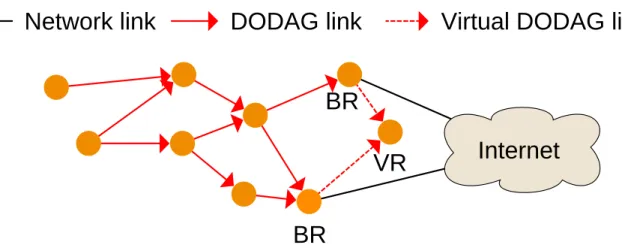
The issues mentioned in Chapter 2 could be solved with one unique mechanism: border router redundancy. The idea is to introduce multiple border routers in one LLN. This would resolve border router failure as nodes could still have an exit point toward the Internet upon failure of one BR. It would also mitigate the funneling effect by distributing the traffic load among multiple exit points. RPL supports the usage of multiple BRs with the concept of virtual DODAG root. The idea is to have multiple DODAG roots acting as standard nodes and pretending to be connected to a unique DODAG root. However the RPL specifications only suggest the concept of virtual DODAG root and do not provide a complete specification. This thesis proposes a complete solution to support border router redundancy in RPL networks to alleviate issues resulting from border router failure or funneling effect. This contribution is presented in Chapter 4.
3.2
Multiple sinks
Multi-sink paradigm introduces BR redundancy and thus mitigates the aforementioned issues. This section presents published scientific works that propose mechanisms to integrate multi-sink into RPL operations. In [22], several RPL-based routing protocols using multi-multi-sink are designed and evaluated through simulations. Each root node advertises its own DODAG with its own RPL Identifiers. A source node selects the closest sink before sending a packet according to the minimal hop count. Performance evaluation of this protocol using different approaches links better results with a higher number of sinks in the network. This work however does not consider the failure of one root node. With their following work [23], the authors propose a RPL-based routing framework aiming to improve RPL performance with different kind of traffic patterns. Multiple gateways are introduced to reduce the memory overhead due to RPL storing mode. The simulation results show overall better performance, but the aforementioned issues are still not considered. A proposal to dynamically augment the
number of sinks in RPL networks is described in [24]. The proposed mechanism introduces ”rescue sinks” in RPL networks deployment. Those sinks would not run until a suffering node calls for help (i.e. a congested node sends DIO with special information). Near rescue sinks would then turn on and absorb a part of the traffic that was originally destined to the suffering node. This idea would not only greatly increase the cost of network deployment, but is also somewhat inefficient as rescue sinks could be used permanently to increase the performance of the network and save nodes’ energy. Furthermore the efficiency of such mechanism would be entirely dependent of the location of each rescue sink, which is not studied thoroughly.
3.2.1
Virtual DODAG root
The concept of Virtual DODAG Root (VR) is first introduced in the RPL specification and will be thoroughly presented in Chapter 4. To put it simply, multiple root nodes that are part of a single DODAG are coordinated to look as if they were one unique root. It aims to offer multiple attachment points to nodes that are part of the DODAG instead of only one. An implementation of multiple LoWPAN border router is presented in [25]. Here, a single root BR maintains the network, while other BRs do not advertise themselves as roots. The difference with simple nodes is that those BRs have a link with an outer network (e.g. Internet) through which they relay messages to the unique DODAG root in the LLN, which in turn forward them to the destination. This eases the traffic load inside the LLN as outer links are preferred if available. However this solution is not optimal as the BRs that are different from the root could directly forward messages to their destination across Internet instead of relaying them to the LLN root. Furthermore, the utility of a central root BR comes from the fact that in IoT networks nodes are not likely to have a direct link to the Internet. The work presented in [26] offers a different design to introduce BR redundancy. Multiple BRs are connected to a common backbone network, into which is located the unique RPL root (i.e. the root is outside of the LLN). All BRs will then be part of the root DODAG as simple nodes, enabling BR redundancy. However this does not allow different networks to be connected to different backbone networks. In [27], the authors propose a mechanism to allow multi-sink support in RPL leveraging a VR. One central unit known as the ”registrar” synchronizes DODAG parameters for all root nodes, thus a VR is created and maintained by the registrar. This enables load balancing as nodes join the DODAG through different roots, but its efficiency is highly dependent on the position of the roots, which had not been studied. Moreover, this work does not take into account the failure of a root node and how orphan nodes could recover from it, nor does it offer a dynamic way to redirect nodes upon congestion once the network is stable. The work presented in [28] proposes a similar way to create a VR in a RPL network. A central unit known as the ”Anchor Agent” (AA) is located outside of the LLN and synchronizes DODAG parameters for all BRs. Load balancing is also introduced thanks to multiple root nodes. On the opposite of the previously cited work, it takes into account the failure of a root node. The AA, upon BR unreachability is able to redirect the IPv6 prefixes from the failed BR to another operating BR. Orphan nodes can then reattach to this new BR and recover from their BR failure, without breaking their ongoing connections as the advertised IPv6 prefix is the same. This mechanism uses IPv6 tunnels, which encapsulate IPv6 packets inside IPv6 packets. However, this increases headers’ size in LLN communications, thus reducing further the size left for data. All those
works suffer from the same weakness: the use of one central device to maintain a VR. As it is operated by real hardware, the virtual root is not properly virtual, thus can face failure. Using a central device on which depends the proper functioning of the routing operations just shifts the single point of failure onto this device.
3.3
Load balancing
Using multi-sink indirectly provides load balancing depending on the localization of the sinks. However it is too hazardous to be really efficient and cannot adapt to dynamic variation of traffic. The authors of [29] propose to leverage the RPL objective function so nodes chose their preferred parent not only based on the metrics presented in 2.1 but also taking into account the load of potential parent. Queue utilization in addition to the hop count is used to compute ranks so nodes privilege uncongested path, thus it provides higher performance than RPL under congestion. However, using several parameters to compute a rank requires to associate a weight with each component. Moreover, different instances may pursue different objectives and thus use different objective function. Also, node redirection is not coordinated, thus upon heavy congestion every path may be congested and nodes will change path over and over without stabilizing. The authors propose a probabilistic parent change to avoid this: each node have a given probability to redirect, therefore this mechanism does not provide optimal redirections. Moreover, we believe that avoiding congestion should not be a specific objective of a network, but rather an inherent mechanism of a routing protocol. The mechanism presented in [30] proposes a load-balancing scheme based on multiple gateways. It is not based on RPL but still aims for 6LoWPAN networks use, and its operations make it very similar to RPL. A Virtual height Level (VL) parameter reflects the load of each node. A node selects the lowest VL in its neighborhood as next hop, thus sharing the load. However, being similar to [29] this mechanism suffers from the same downsides as well. In [31], a mechanism leveraging cooperative multiple instances based on game theory is proposed. It leverages the use of multiple instances within a single RPL network supervised by a single root. Cooperation between nodes that are part of different instances results in better overall performance. However this work does not consider BR failure nor does it provide a failover mechanism between instances. A coordination framework is proposed in [32]. This mechanism enables information piggybacking over DIO message. When a node that is part of a DODAG overhears DIOs from another DODAG, it records and transmits those with its own DAOs. Information is carried over to the DODAG root, which allows distinct networks roots to discover themselves and exchange metrics to optimize their network. Then roots can decrease the radius of DIOs transmissions to indirectly redirect nodes to a neighbor root, thus balancing the traffic load. Though it does not allow for precise redirection or consider BR failure, this is an interesting mechanism to which we will refer later in our contribution as it allows co-located BR to discover each other and exchange initialization information.
In this chapter, we have seen the scientific works related to the subject of this thesis. We briefly exposed why we think those works do not fully resolve the issues raised by BR failure and funneling effect. The next chapter will detail our own contribution.
CHAPTER
4
CONTRIBUTION: RPL-NAT-LB
The previous Chapter explained why, in our opinion, the existing scientific works related to RPL issues introduced in Chapter 2 do not provide a sufficient answer. Thus in this thesis we propose an original contribution which aims at alleviating BR failure and funneling effect. Our contribution, called RPL with Network Address Translation and Load Balancing (RPL-NAT-LB) is composed of three parts: first part follows the hint of the RPL RFC and introduces border router redundancy in LLNs. Second part uses the Network Address Translation (NAT) protocol to enable multiple IPv6 prefixes support between cooperating BRs. Third and final part introduces a load-balancing mechanism to alleviate the funneling effect.
4.1
Considered IoT scenario
Our solution was designed according to our vision of the most likely IoT networks deployment scenario. Our guess is that IoT networks will be widely spread in home, urban and industrial environments, thus many networks would be colocated with others. IoT networks would be composed of different devices, produced by different companies, competing for control over the communication medium (most likely the air). We propose to leverage this colocation to enable cooperation between networks. In industrial environments, an economical obstacle could exist as companies would not want their network to cooperate with a competitor’s one. However regarding urban and home networks, we think that the main matter of concern is network efficiency. Thus, colocated networks could share links and nodes to mitigate the nefarious effects steming from BR failure and funneling effect.
4.2
Multiple border routers
Taking into account the considered scenario, each colocated IoT network would have one ded-icated BR for its own network. Therefore if we can enable BRs coordination, BR redundancy would come at no additional cost.
4.2.1
Motivations
Multiple BRs in a single network bring multiple advantages: first, it increases the resilience of the network, as upon BR failure another could retrieve the orphan nodes, thus preserving their Internet connectivity. Secondly it offers load balancing, as the traffic load can be shared between multiple exit points. Moreover, BR redundancy can enable multi-homing support. Multi-homing occurs when a single network have multiple Internet accesses via
multiple Internet Service Providers (ISPs). Thus if one ISP undergo failure resulting in loss of Internet connectivity for its clients, a multi-homed network would maintain Internet connectivity through another ISP. Multi-homing provides load balancing as well as traffic load can be splitted between ISPs. Considering our scenario, different BRs from different networks may have different ISPs, which would enable multi-homing. BR redundancy was hinted by the RPL specification with the concept of virtual DODAG root.
4.2.2
Virtual DODAG root
The Virtual DODAG Root (VR) was first introduced in [11], but this document did not fully specified how it should be operating. As illustrated in Figure 4.1, a VR is obtained when multiple BRs from an unique RPL network coordinate themselves to act as if they were a unique DODAG root. This introduces BR redundancy without the need to modify deeply RPL operations. Therefore, the first part of our contribution enables VR support in a similar way to [27, 28]. All BRs maintaining the VR share the same RPL identifiers presented in Chapter 2, and use the same IPv6 addresses. Thus, all BRs are part of and maintain the same DODAG. All BRs send the same DIO, therefore nodes joining the DODAG only see one sole BR on network layer, and they can then join the nearest BR. As each BR keeps its unique MAC address, the differentiation between them is done on link layer. Using a VR requires parameters synchronization between BRs before starting the dissemination of DIO messages. BRs must also regularly update RPL identifiers as they may change (e.g. upon global repair). Works presented in [27, 28] use a central synchronizing point to maintain and distribute RPL parameters among BRs. In contrast to those, we use a distributed mechanism instead of a central one. Using an opportunist discover scheme between BRs from distinct networks, similarly to what is proposed in [32], BRs could discover themselves and then exchange their public IPv6 with piggybacking over control messages if needed (i.e. BRs not in direct radio reach of each others). They could then share the DODAG parameters and start maintaining a VR and a new DODAG. This benefits from the advantages of using a VR while avoiding the single point of failure represented by an unique synchronization point. Unfortunately, considering our privileged scenario one issue could arise as different IPv6 prefixes may be used in different networks.
4.3
Multiple IPv6 prefixes
A global IPv6 network address is composed of three parts: the routing prefix, the subnet ID and the interface ID. The network prefix is the union of the routing prefix and the subnet ID. It identifies a given network, while the interface ID points to a given device part of this network. Different IPv6 networks should use different IPv6 network prefixes.
4.3.1
Motivations
The DODAGID RPL identifier refers to a unique DODAG, and is also the IPv6 address of a the DODAG root. In LLNs, BRs can distribute the IPv6 prefix used by the nodes taking part in the network, thus the DODAGID of a given BR is based on its prefix. The
BR
DODAG link
Internet
BR
VR
Virtual DODAG link
Network link
Figure 4.1: Virtual DODAG root
DODAGID is shared between all of the BRs taking part in a VR. Considering our scenario, distinct networks owned by different companies are likely to use and announce different IPv6 prefixes, thus raising a conflict with the use of a VR. BRs must synchronize and distribute one unique IPv6 prefix in the LLN, as BRs from the same VR share the same DODAGID and cannot use different IPv6 prefixes. Therefore, BR must synchronize on using one same IPv6 prefix in the DODAG, though as BRs may not be connected to the same backbone network, they may not be able to announce the same IPv6 prefix. The first motivation for multi-prefixes support is to resolve this issue. Furthermore, enabling multi-prefixes support could help enable IPv6 mobility as well. IPv6 mobility lets a device move from one network to another without having to change its IPv6 address. Without IPv6 mobility, a node that switches networks (e.g. upon BR failure) must discard its current address and configure a new one according to the new prefix. This requires time and resources and also breaks all ongoing communication with hosts located across the Internet. Moreover, most if not all of the works referenced in Chapter 3 make the hypothesis that the whole network uses one same IPv6 prefix. While this may be reasonable in the deployment of lone networks, we think that it is less likely to be a valid requirement when considering the cooperation of multiple networks owned by the different organizations.
4.3.2
Network address translation
Network Address Translation (NAT) is a widely used protocol in IPv4 networks. This mech-anism specified in [33] was the main crutch preventing IPv4 to collapse from address exhaus-tion. The principle of NAT is to match IP addresses with corresponding IP addresses. It was often used in IPv4 networks to assign one public IP address to a whole private subnet composed of several hosts. Although NAT has provided many benefits, it was the cause of some difficulties as well: as the association of an host located in a private network was done on connection initialization, it was not possible to initiate a connection with an host located behind a NAT as it was (e.g. when running a server). When IPv6 was specified, one of the objectives was to get rid of NAT to avoid those issues. With the huge pool of IPv6 addresses,
Network link
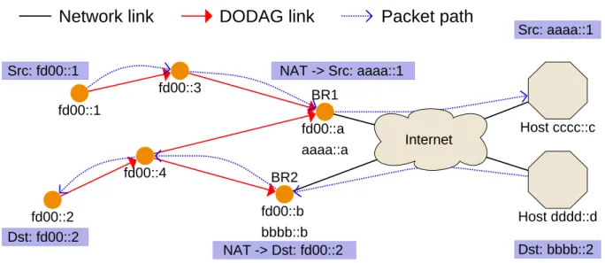
fd00::1 fd00::4 BR2 fd00::b bbbb::b BR1 fd00::a aaaa::a fd00::2 fd00::3 Internet Src: fd00::1 NAT -> Src: aaaa::1 Src: aaaa::1 Dst: bbbb::2 NAT -> Dst: fd00::2 Dst: fd00::2 Host cccc::c Host dddd::dDODAG link
Packet path
Figure 4.2: NAT example - address translation upon packet fowarding
each host can have is own IPv6 address without risking address exhaustion. Despite this, a specification for IPv6 NAT still exists [34]. One of the justification to use NAT with IPv6 is that it can help enable multi-homing. Thus, in the second part of our contribution we adapted the NAT protocol within RPL to use an unique local prefix to synchronize multiple networks using different prefixes. BRs can each announce a different prefix, but they will distribute a default Unique Local IPv6 Unicast Addresses (ULA) prefix [35] into the LLN. Therefore, as illustrated in Figure 4.2, BRs will translate the source’s or destination’s IPv6 address depending on the packet’s destination before forwarding. Every node will then be able to communicate with all nodes from another network regarding RPL operations as they will use the same IPv6 prefix. Cooperating BRs can then share their IPv6 prefixes through the Internet and position themselves as backup routes for prefixes owned by colocated BRs. Upon a BR failure, orphan nodes can join a neighbor BR while keeping the same IPv6 address, therefore preserving their connections with hosts across the Internet.
4.4
Load balancing
Hosts in the same network may not produce the same amount of traffic quantity. Load balancing is the action of evenly splitting the traffic load between hosts and intermediate devices, aiming at avoiding bottlenecks and uneven workload distribution. This is even more important in LLN than in classic IP networks because of the limited amount of energy and the multi-hop topologies.
4.4.1
Motivations
While the first two parts of our contribution solve BR failure, they only partially solve funneling effect. Bottlenecks may stem from the funneling effect, which in turn cause heavy congestion in the network. Using multiple BRs shares the load depending on the position of
those nodes, but it cannot alleviate dynamic congestion. A new load balancing mechanism could allow to dynamically share the load, thus reducing the risk of congestion and energy depletion inequality. We find referenced works in Chapter 3 not totally satisfying, hence we propose a new mechanism to dynamically balance the traffic load.
4.4.2
Prerequisites
Therefore, the third part of our contribution is a flexible mechanism to explicitly redirect nodes from a congested network to a less loaded one. Automatic redirection decided by the nodes themselves, similarly to [29], is fast and does not increase the control traffic in the network. However, this allows imprecise redirection to take place, which may only improve the connectivity of a single node while handicapping another part of the network. Moreover, this can cause jitter as nodes may not stabilize (e.g. if the whole network is heavily loaded). Instead, we propose an explicit redirection mechanism supervised by the cooperating BRs. This enables optimal node redirection from a global network point-of-view. This, however, has two prerequisites: first, we need to use the non-storing mode of downward routing of RPL. With non-storing, the BR of a network will receive all DAOs from all of the nodes joining its LLN, while using the storing mode does not guaranty that DAOs will travel all the way to the BR (not forwarded by the first node that already knows the advertised destination). If a BR receives all DAOs from its child nodes, it then knows all the nodes of its DODAG and their parent. Secondly, because of the VR, the BRs all look the same on network layer. Thus, we use RPL instances to differentiate which BR each node is attached to: each BR uses a unique RPLInstanceID. Each node is then a part of only one instance, and upon explicit redirection from its BR, must switch to another instance.
4.4.3
Explicit redirection
We define a redirectable node as one that has one or more neighbor nodes from a different RPL instance, which is learned when receiving DIOs. Upon reception of a DIO from a different instance, a node activates a special Redirectable Flag (RF) in its DAOs. A redirectable node also retains the IPv6 and link addresses from the best node (i.e. lowest rank) of another instance. DAOs are transmitted regularly, thus a BR quickly knows each redirectable node from its DODAG. In order to avoid bad links, a node sets its RF to 0 if it does not receive a DIO from another instance after two DIO intervals.
A BR has two modes in our protocol: normal and congested. In normal mode, the classic RPL operations are conducted. A BR enter congested mode depending on an user de-fined trigger (e.g. max sub-DODAG size, queue losses, etc). BRs can dynamically exchange DODAG information between them via the Internet (e.g. sub-DODAG size) and enter con-gested mode depending on specific calculation (e.g. significant difference in the sub-DODAG size). Cycling through its node list, a congested BR chooses the best nodes to redirect (e.g. if it needs to redirect X nodes, it redirects one node with X-1 children). Then, a BR sends in unicast a new control message that we introduced to redirect nodes, known as a DODAG Redirection Solicitation (DRS), and deletes the redirected node from its sub-DODAG list. As for now, a DRS is a simple ICMPv6 message containing no additional information. Those
X
DRS DIS DIO 6Network link
Internet
5 4 BR2 BR1 3 1 2DODAG link
Control messages
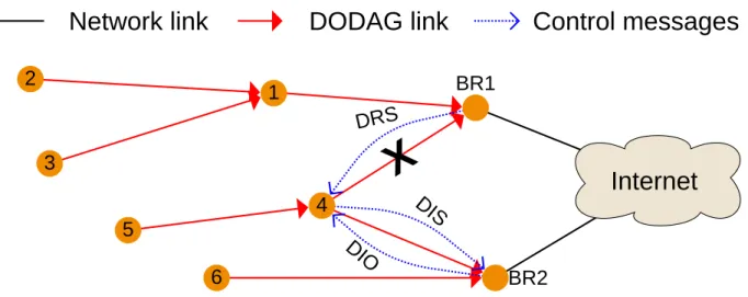
Figure 4.3: Redirection example - overloaded BR1 redirects nodes 4 and 5 with a DRS, node 4 join BR2’s instance and node 5 follows it
operations are repeated until the congested mode trigger is released (e.g. even sub-DODAGs size between BRs).
Upon DRS reception, a node enters a transitioning redirection state. It first sends a unicast DIS to the best node from a different instance it has seen before using the retained addresses, to receive a fresh DIO instead of storing one that could potentially be obsolete at the moment of DRS reception. Upon DIO reception the node switches instances and joins another new DODAG from the another instance. However, upon non reception of a DIO before next DAO transmission, this node stops its redirection and turns off its RF. This allows nodes to keep their connectivity until effective redirection, thus avoiding the traffic loss that could occur within DRS and DIO reception. Furthermore, if a node receives a DIO from their preferred parent with a different RPLInstanceID, they immediately follow it to the new instance based on the received DIO. This enables multiple redirections with one DRS, and avoid issues occurring when a BR could redirect a node before receiving DAOs from its children. Those operations are illustrated in Figure 4.3.
Throughout this chapter, we have detailed each part of our proposal, known as RPL-NAT-LB. The VR alleviates BR failure, the NAT protocol enables multi-prefixes support and the explicit redirection with DRS mitigates congestion steming from funneling effect. In the next chapter, we will present the implementation and experimentation of our proposal.
CHAPTER
5
EXPERIMENTATION
This chapter first presents our proposal implementation under Contiki OS. Then we de-tail the experiments conducted on FIT/IoT-LAB along with the results obtained from our contribution compared to RPL.
5.1
Implementation
To assess the efficiency of our proposal, it was implemented based on the existing open-source code of a well-used IoT operating system, known as Contiki.
5.1.1
Contiki OS
Our implementation uses Contiki OS version 3.x. Contiki OS [36] is a lightweight open-source operating system for IoT devices. It was created by Adams Dunkel in 2002 and was since improved by many scientists and industrial actors around the globe. It has become one of the most used operating systems for IoT. We have choosen to implement our contribution under Contiki for several reasons: firstly Contiki is widely spread and widely used. Secondly, it is supported by our testbed platform, and finally it is entirely written with the C programming language. Contiki comes with a full IPv6 network stack as well as an implementation of the RPL standard, known as Contiki RPL.
5.1.2
Cooja
Contiki provides its very own wireless network simulator, known as Cooja. Cooja is a simu-lator with emusimu-lator capabilities, as it offers to emulate different node hardware, which allows to obtain more precise results than basic simulation. While results obtained by simulations will not be presented here, we find it fair to mention Cooja anyway as it was a useful tool to quickly implement new features in Contiki OS and test those under a controlled environment.
5.1.3
Implementation cost
Our implementation cost in terms of memory used (in bytes) is visible in Table 5.1. Regarding the border router firmware, our contribution compared to using RPL enlarge the firmware by 5884 bytes. As for the node firmware, compared to using RPL, using our contribution enlarge the firmware by 5200 bytes. In perspective with the harware of the motes used in our experiments (cf. Table 5.2), we find the size difference to be acceptable.
Border router Node RPL 1063744B 1100896B RPL-NAT-LB 1069628B 1106096B Table 5.1: Compiled firmwares’ sizes in bytes
Microcontroller unit ARM Cortex M3 Architecture 32 bits
Frequency 72 MHz
Random access memory 64 kB Read-only memory 16 MB
Radio chip AT86RF231 Table 5.2: M3 open node hardware
5.2
Experiment setup
We started to experiment on a real testbed with our contribution implemented on top of Contiki RPL. This section introduces the IoT-LAB testbed on which we have tested our proposal, as well as the test scenario and network layout we used.
5.2.1
FIT/IoT-LAB
We chose to conduct our experiments on a real testbed known as FIT/LAB [37]. IoT-Lab is one of the platforms provided by the Future Internet of Things (FIT) project [3]. It is a large scale testbed allowing any computer scientist to test wireless networks composed of small and constrained devices. The testbed is located in six different cities in France, and is composed of a total of 1791 wireless sensor nodes. IoT-Lab offers a tool box as well as an SSH frontend to quickly launch experiments and retrieve results trough the serial link of each node. The testbed is composed of different hardware offering different testing environments, like different hardware or even mobile nodes. Our contribution was evaluated using the testbed from the IoT-Lab site located in Illkirch-Graffenstaden. We used the M3 nodes provided in IoT-Lab, whose hardware capabilities are presented in Table 5.2.
5.2.2
Experimental parameters
Experimental parameters used for the tests can be found in Table 5.3. As Media Access Control (MAC) layer, we have decided to use the simplest protocol available in Contiki, as the aim of our work is not to evaluate the performance of the MAC layer. The role of the MAC layer is to control the radio scheduling of each node and to avoid radio collisions. Carrier Sense Multiple Access Collision Avoidance (CSMA/CA) is a widely used MAC protocols in classic wireless networks such as Wi-Fi. Using CSMA, each node competes for the use of the shared communication medium (the air). If a collision is detected, the transmitting node stops, waits and after random backoff time, retries to transmit its data. We enabled the acknowledgment mechanism proposed by 802.15.4, in order for the nodes to know when a
MAC layer IEEE 802.15.4 CSMA/CA MAC acknowledgments Enabled
MAC Tx queue size 1 packet
RDC mechanism No RDC (NULLRDC) Traffic type UDP packets
Traffic rate 1 packet per second
Tx power 3 dBm
Rx power threshold -60 dBm Motes used 10 M3 open node
RPL mode Non-storing
RPL OF MRHOF ETX
Congested mode trigger Sub-DODAG size threshold Table 5.3: Experimental parameters
frame was lost and to retransmit it. We have also reduced the size of the waiting transmission queue of nodes in the network, to introduce congestion without having to use a large number of nodes or to saturate the link.
Regarding the Radio Duty Cycling (RDC) mechanism, we chose to use the NULLRDC available in Contiki as we do not intend to evaluate RDC mechanisms. The role of a RDC mechanism is to save energy by turning off the radio chip when it is not needed, while at the same time trying to preserve performance as much as possible. NULLRDC simply does nothing (i.e. the radio chip is on all the time), which corresponds to a RDC ratio of 100%. Nodes in the network generated traffic which was simple UDP packets, containing a single integer corresponding to the sequence number of the packet. Such packets were sent at a rate of one per second. The transmission power was left at its maximum capability with M3 motes, which is 3 dBm. However, we reduced the reception power threshold to -60 dBm. This means that transmission would be forwarded from the physical layer to the link layer only when they would be of a minimum quality represented by the threshold value, allowing us to have control over the RPL topology. We used a total of 10 M3 motes for our experiments. RPL mode of operation for building downward routes was non-storing, to have the root nodes know every node from their sub-DODAG. RPL objective function was MRHOF, using the ETX metric, as this is a rather well accurate and widely used link quality estimator. Finally, the trigger we used for congested mode was a threshold on one’s BR sub-DODAG size equal to the total number of nodes divided by the number of BRs.
5.2.3
Network layout and scenario
To assess the efficiency of our proposal, we tested it on a controlled topology, in order to understand the observed results. We used 10 M3 nodes of IoT-LAB, two of which were BR, and the 8 other were simple nodes sending a regular amount of traffic destined to an host outside of the network. The nodes’ output was collected through the serial link for each one of the 8 traffic generating nodes. Regarding the two BR, a Serial Link IP (SLIP) tunnel was used to collect BR output as well as to send the prefix that each BR should distribute.
Figure 5.1: Physical topology of the testbed
This tunnel enables IP packet transmission through a serial link, thus allowing us to receive packets coming from the LLN on our computer. The physical topology of the network is visible in Figure 5.1. All the M3 motes of the Strasbourg site are represented. The blue ones are those we used in our experiments, along with their corresponding node ID. We chose to use the two nodes with the more distance to each other as BR, nodes 18 and 53. In our scenario, we wanted to recreate what could happen when a new network boots in colocation of a stable one. Therefore, the BR node 53 starts 60 seconds latter than the BR node 18. The 8 other nodes that are not BR start to transmit UDP packets at a rate of 1 packet per second after 30 seconds. The expected result is that by the time node 53 awakes, all 8 other nodes would have already joined the DODAG of node 18 and started to transmit data destined to an outer host. Thus the network would experience congestion, to which RPL would not be able to recover, while our proposal could balance the traffic load. As the topology is usually stable after about 10 minutes, we chose to make each experiment last for an hour. In order to have statistically significant results, we launched a total of 100 experiments. Half were using RPL and half RPL-NAT-LB. In the next section, we will present the results we obtained from those experiments.
5.3
Results
In this section, we first show the DODAG obtained from the experiments. Then we introduce the collected metrics to evaluate the performance of RPL-NAT-LB and RPL. We finally present the obtained results under the experiment conditions described in the last section.
![Figure 1.1: ICube organization chart (from the ICube website [1])](https://thumb-eu.123doks.com/thumbv2/123doknet/14685086.744385/7.918.136.788.132.599/figure-icube-organization-chart-icube-website.webp)