RESEARCH OUTPUTS / RÉSULTATS DE RECHERCHE
Author(s) - Auteur(s) :
Publication date - Date de publication :
Permanent link - Permalien :
Rights / License - Licence de droit d’auteur :
Institutional Repository - Research Portal
Dépôt Institutionnel - Portail de la Recherche
researchportal.unamur.be
University of Namur
Engineering Configuration Graphical User Interfaces: A Model-based Perspective
Boucher, Quentin; Perrouin, Gilles; Acher, Mathieu; Heymans, Patrick
Publication date:
2012
Document Version
Early version, also known as pre-print
Link to publication
Citation for pulished version (HARVARD):
Boucher, Q, Perrouin, G, Acher, M & Heymans, P 2012, Engineering Configuration Graphical User Interfaces: A
Model-based Perspective: Paper submitted to ECMFA'12..
General rights
Copyright and moral rights for the publications made accessible in the public portal are retained by the authors and/or other copyright owners and it is a condition of accessing publications that users recognise and abide by the legal requirements associated with these rights. • Users may download and print one copy of any publication from the public portal for the purpose of private study or research. • You may not further distribute the material or use it for any profit-making activity or commercial gain
• You may freely distribute the URL identifying the publication in the public portal ?
Take down policy
If you believe that this document breaches copyright please contact us providing details, and we will remove access to the work immediately and investigate your claim.
University of Namur Rue Grandgagnage, 21 B-5000 Namur
Belgium
T
ECHNICAL
R
EPORT
Friday 2ndMarch, 2012AUTHORS Q. Boucher, G. Perrouin, M. Acher, P. Heymans APPROVED BY P. Heymans
EMAILS {qbo,gpe,mac,phe}@info.fundp.ac.be STATUS Paper submitted to ECMFA’12
REFERENCE P-CS-TR ECMFA-000001 PROJECT NAPLES
FUNDING La Wallonie
Engineering Configuration Graphical User Interfaces: A
Model-based Perspective
Interfaces: A Model-based Perspective
Quentin Boucher1, Gilles Perrouin1, Mathieu Acher1, and Patrick Heymans1,2
1 PReCISE Research Centre, University of Namur, Belgium 2 INRIA Lille-Nord Europe, Universit´e Lille 1 – LIFL – CNRS , France
{qbo,gpe,mac,phe}@info.fundp.ac.be
Abstract. Mass popularisation of configurable solutions is a priority of most companies. Hundreds of configurators with an interactive graphi-cal user interface (GUI) are developed to assist customers in activating or deactivating a large number of inter-related configuration options. In practice, such complex configuration GUIs are developed in an ad hoc manner (e.g., configuration rules are hard-coded), raising several issues in terms of correctness, flexibility and maintenance. In this paper, we adopt a model-based perspective for comprehensively engineering con-figuration GUIs. We rely on feature models to describe concon-figuration op-tions and their complex relaop-tionships. We propose a generic model-based architecture for engineering configuration GUIs, in which well-defined and scalable reasoning operations can be integrated. We design and de-velop model transformations that can generate customised configuration GUI elements from feature models. We illustrate the approach using the Mozilla’s XUL GUI environment.
1
Introduction
In a more and more competitive environment, product customisation is taken to the extreme by companies in order to gain market share. Companies provide customisation tools, more commonly called product configurators, to assist their customers in deciding upon the characteristics of the product to be delivered. This trend is further strengthened by the ever growing presence of such config-urators on the Internet: the reference [1] lists more than 800 of those web-based configurators coming from 28 domains, from car to food including apparel. How-ever, unreliable and poorly designed configurators can rapidly become a strong handicap. In particular, configurators should preclude inconsistent activation or deactivation of configuration options while proposing appropriate, user-friendly graphical user interface (GUI).
Our experience reveals that some existing configurators are implemented in an ad hoc fashion. For instance, we have observed in two industrial cases that re-lationships between configuration options are hard-coded and mixed with GUIs’ code. As constraints are scattered in the source code, severe maintenance issues
occur. For example, engineers are likely to introduce errors when updating or adding new constraints between options in the configurator. Moreover, as recog-nized by our industrial partners developing such configurators, the correctness and the efficiency of the reasoning operations are not guaranteed. More reliable and maintainable solutions are thus needed.
In this paper, we explore a pragmatic and model-driven way to generate con-figuration GUIs. We rely on feature models (FMs) to represent and reason about the configuration options and their complex relationships. FMs have been inten-sively studied by academics during the last two decades in the software product line community [2]. FMs are now equipped with formal semantics [3], auto-mated reasoning operations and benchmarks [4, 5], tools [6–8] and languages [9, 10]. In essence, an FM aims at defining legal combinations of features autho-rised or supported by a system. In our case, configuration options are modelled as features and each configuration (specification of a product) authorised by the configurator corresponds to a valid combination of features in an FM. A strength of FMs is that state-of-the-art reasoning techniques, based on solvers (e.g., SAT/SMT/CSP), can be reused to implement decision verification, prop-agation, and auto-completion in a rigorous and efficient way [4, 9, 11]. Therefore FMs are a very good candidate to pilot the configuration process during which customers decide which features are included in a product.
Once FMs have been elaborated, there is still need to produce a GUI, includ-ing the integration of underlyinclud-ing reasoninclud-ing mechanisms to control and update the GUI elements. On the one hand, some FM-based configuration GUIs rely on solvers [6–8]. But such GUIs do not consider presentation concerns and their generation process is rigid, avoiding the derivation of customised GUIs [12]. Fur-thermore existing graphical representations of FMs (e.g., FODA-like notation or tree-views) are not adapted to user-friendly configuration [13]. On the other hand, model-based approaches for generating GUIs simply produce the visual aspects of a GUI [14–17]. This is not sufficient for configurators since constraints’ verification is paramount for their usability and performance.
Our approach is to combine the best of both worlds, i.e., correct configu-rations together with user-friendly generated GUIs. We present a model–view– controller (MVC) architecture to design configurators, which separates concerns between an FM (configuration options modelling), its associated solver (au-tomated reasoning support) and the presentation of the GUI. To fill the gap between FMs and configurators’ GUIs, the di↵erent constructions of the FM formalism are restituted as GUI elements through model transformations. The transformations are based on a metamodel for TVL [10], a textual language for feature modelling. Transformations can be parameterised to derive specific configuration GUIs. We use model-to-text transformation rules to show how to translate a TVL model into a XUL GUI, XUL being the XML-based UI language of the Mozilla Foundation.
Structure of the paper. In Section 2, we describe the problem of engi-neering configuration GUIs, report our experience in industry and discuss the related work. In Section 3, we present TVL and its metamodel. In Section 4, we
sketch our MVC-like configurator architecture. We also detail how configuration GUIs can be generated and customised from a TVL specification, using XUL as a target language. In Section 5, we discuss key properties of our model-based approach and outline research directions. Section 6 concludes the paper.
2
On Engineering Configurators
2.1 Challenges
The cornerstone of a configuration is the reasoning engine that is responsible for keeping the configuration environment consistent by handling user’s deci-sions, instantiating constraints, propagating the results and managing (usually preventing) conflictual decisions. Another crucial aspect of a configurator is the GUI proposed to customers. By simplifying and facilitating the configuration process, a configurator should compensate for consumers’ lack of technical ex-pertise. In this way, the configuration GUI becomes a decisive criterion for cus-tomer satisfaction. Our preliminary investigation of web-configurators design and our experience acquired during industry collaborations reveal that existing configurators are developed in an ad hoc fashion:
– practitioners reinvent the wheel when implementing the reasoning engine: operations are not formally defined, raising correctness or runtime efficiency issues;
– the logical relationships between configuration options are hard-coded, in-ducing sever maintenance overheads;
– the GUI itself is very rigid, hindering reuse across platforms (e.g., web-based vs standalone vs mobile) and its customisation to user profiles.
More specifically, we report on two industrial collaborations. In the first case, the company develops critical communication systems and uses a configurator to parameterise their deployment as well as their behaviour at runtime. Thousands of configuration options are proposed in a Qt interface and all the code is written in C++. We observed that i) the reasoning operations essentially consist in a set of if-then-else instructions; ii) numerous portions of code have been manually duplicated to realize the logics and update the GUIs; iii) the reasoning opera-tions are scattered in di↵erent places (C++ files); iv) constraints are documented in natural language through comments. As recognised by engineers, the logical part of the configurator is difficult to maintain and evolve while the reasoning operations have not been designed to guarantee decision verification and propa-gation. In the second case, the company develops an all-in-one tool that guides document preparation including the customisation of printing options and the preview of documents. In the current version of the tool, mismatches between the preview and the actual output can occur, and, in rare cases, documents may not even be printable on the selected printer. Indeed, only some constraints im-posed by the printers are implemented in the source code, mostly for time and complexity reasons. According to the engineers, implementing those constraints
is a complex task since it requires to have an overview of the complete archi-tecture of the tool. In both industrial cases, our partners expressed their need to migrate their legacy configurators towards more reliable, maintainable, and flexible solutions.
2.2 A Model-based Perspective
To address the issues raised when engineering configurators, we argue that the configuration options and their complex and often large number of logical rela-tionships should be properly described in a dedicated model (i.e., an FM). How the model is elaborated [18] or reverse engineered [19, 20] is an important issue but out of the scope of this paper. The expected benefits of using a model-based approach are as follows:
Reliability and efficiency. State-of-the-art reasoning techniques (i.e., SAT/SMT solvers) can be reused and generated from the FM in order to manage (e.g., control, propagate) the selection/deselection of configuration options; Maintenance. The specification of constraints is well-defined and centralized
in one place, instead of being informally documented and scattered in the source code;
Flexibility. Some elements of the FM can be customised into concrete GUI elements through model transformations.
2.3 Related Work
Model-based generation of GUIs is an important research field in the HCI com-munity. A whole spectrum of approaches ranging from purely manual design to completely automated approaches have been proposed. On the one hand, a manual design is not adequate in our context. Mechanisms for reasoning about customers’ interactions and for updating accordingly some graphical elements should be automatically derived. On the other hand, fully automatic approaches generally fail to produce good GUIs.
Consequently, we focus on partially automated approaches which make up the bulk of existing literature. Most of those approaches store extra informa-tion for GUI derivainforma-tion in models. It is referred as Model-based User Interface Development (MBUID) and is generally supported by a dedicated environment. The di↵erent MBUIDs and their environments have been surveyed by Gomaa et al. [14]. However, none of them addresses the specific issues that arise when gen-erating configurators like the integration of underlying reasoning mechanisms for controlling and propagating customers’ choices in the GUI. Modelling techniques have been developed to support adaptations of interfaces at runtime [16, 17]. In the same way, configurators should be adapted to reflect the customers’ inter-actions (i.e., selections/deselections). In our context, the kind of modifications applied to the configurator interfaces are typically lightweight (e.g., some values are greyed) and can be predicted. Moreover, we can take advantage of planned variability to make use of efficient solvers to manage the configuration process.
In the software product line community, most existing variability-related tools represent feature models (and allow users to configure them) using tree-views. We can mention pure::variants [6], FeatureIDE [7] or Feature Modeling Plug-in [8]. Those tools have a graphical interface in which users can select/dese-lect features in a directory-tree like interface where constraints are automatically propagated. Several visualisation techniques have been proposed to represent FMs [13], but they are not dedicated to end users which are more accustomed to standard interfaces such as widgets, screens, etc. An exception is the AHEAD tool suite of Batory et al. [12]. Simple Java configuration interfaces including checkboxes, radio buttons, etc. are generated using beautifying annotations sup-ported by the GUIDSL syntax. Such configurators cannot be put into the hands of end users as they are tool dependent, i.e., they cannot be included into an existing GUI like a company’s web page. Furthermore, tree-views are too basic and not adapted for the majority of end users.
For completeness, we also have to mention that several authors combined MBUID approaches with FMs. Among them, we can mention Pleuss et al. who automatically derive the individual GUI design corresponding to a configured product [21]. However, we pursue di↵erent goals: Pleuss et al. aim at generat-ing the GUI of products derived from the product line while our interest is on generating the interface of a configurator allowing end users to derive products according to their needs. Schlee and Vanderdonckt [22] also combined FMs with GUI generation. The variability of the interface is modelled with an FM, which will be used to derive the corresponding GUI. Their work is closer to ours but seems abandoned since 2004. They do not address all the issues mentioned above (e.g., customisation, reasoning).
3
Modelling Configuration Options
In sharp contrast with current practice where configuration specification and reasoning are mixed with GUI implementation, we believe that the specification of configuration options should be done explicitly and independently from the GUI. As discussed in the introduction, an FM can be used to this end. FMs are tree-like, directed acyclic graphs whose nodes denote features and whose edges represent top-down hierarchical decomposition of features. Almost all existing FM languages are based on the FODA notation [2] which uses graphs with nodes and edges in a 2D space, so called feature diagrams. Over time, textual alternatives to graphical representations have been proposed [23, 9]. Reasons for that trend are the apparent difficulty to navigate, search and interpret large FMs. Furthermore, the constructs available or displayed are usually limited.
3.1 TVL
To cope with the limitation of existing notations, we proposed TVL [10], a tex-tual FM language targeted to software architects and engineers and supported by formal analysis tools. TVL can represent FMs that are either trees or directed
acyclic graphs. The language supports standard feature decomposition opera-tors: or - (group someOf keyword), xor - (group oneOf), and - (group allOf), cardinality-based- (group [m..n]) decompositions. Optional features can also be declared using the opt keyword. Five di↵erent types of feature attributes are supported: integer (int), real (real), Boolean (bool), structure (struct) and enumeration (enum). The domain of an attribute can be restricted to a predefined set of values using the in keyword. Attributes can also be assigned fixed or calculated values using the is keyword. Several standard operators are available for calculated attributes (e.g. arithmetic operations). Their value can also be computed using aggregation functions over lists of attributes. In FMs, constraints can be attached to features to define relationships between features and/or attributes. For example, the selection of a feature could require the selec-tion of another one or, oppositely, prevent the selecselec-tion of a third one. In TVL, constraints are Boolean expressions that can be added to the body of a feature.
(a) TVL FM Voting Encoder VoteValues Yes No Abstain [2..*] Role Manager Voter DefaultVote Yes No a And-decomposition group cardinality [i..j] a a Xor-decomposition Legend <requires> <require s>
(b) A possible FODA representation
Fig. 1: PloneMeeting FM
Fig. 1(a) illustrates some of the concepts defined above. It is an excerpt of the complete FM we built for the voting system of PloneMeeting, the meeting management project of PloneGov3. A possible representation in FODA
nota-tion [2] of the TVL model is proposed in Fig. 1(b). As there is a gap between the FODA notation and TVL, we take the liberty of translating enumeration attributes as subfeatures.
3.2 TVL Metamodel
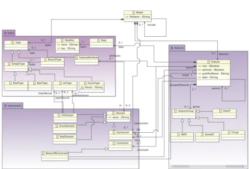
Our approach to configuration GUIs engineering is generative, that is, from TVL models, we aim at generating customised configurators. We need representations of TVL models to transform their elements (e.g., features) into concrete config-uration GUI elements. Hence, the first task is to provide a metamodel for TVL on top of which model transformations can be defined. We rely on the Eclipse Modelling Framework (EMF), a widely used open source modelling environment exploited by most of model transformation languages. Fig. 2 presents an excerpt of the metamodel we have defined for the TVL language.
Fig. 2: TVL metamodel (excerpt)
The entry point is the metaclass Model which contains all the elements of a given TVL specification and may refer to other specifications if needed. The metamodel is organised around three main packages:
– Types: The types package describes standard TVL types instances of ab-stract metaclass Type. real is mapped to RealType, int to IntType, struct to RecordType and so on. These types are used to specify feature attributes through the FeatureAttribute metaclass. Data models informal key/value pairs.
– Features: The features package models the variability part of TVL. Groups are defined as instances of the abstract FeatureGroup metaclass. The option-ality of a feature (opt keyword) is modelled through the optional attribute and the root attribute specifies whether the feature is at the top of the decomposition hierarchy.
– Expressions: The expressions package is responsible for modelling fea-ture expressions, domain restriction on types (instance of the abstract meta-class Domain) and constraints (only “requires” and “excludes” constraints are shown here).
4
Model-based Infrastructure for Configurator
Generation
In this section, we present a model-based infrastructure for engineering configu-rators. We first introduce a generic architecture to integrate the reasoning
facil-ities of the FM into the GUI. We then exemplify how such an architecture can be realized by means of model transformations that generate the configuration GUI, including generic controller components for managing user’s decisions. 4.1 An Architectural Pattern for Configurators
The role of software architecture in the reusability and evolvability of software has long been acknowledged. We rely on design patterns to define a generic ar-chitecture for configuration interfaces. The key idea is to separate variability reasoning done on the FM, event handling (user actions) and the actual rep-resentation of the GUI. Thus, our architecture is inspired by the Model-View-Controller (MVC) pattern [24] and is decomposed in three tiers (see Fig. 3).
User action Update FM
Notify Update GUI Forward update Changes Configuration API SAT/SMT Solver Reasoning layer Control layer Presentation layer Controller View model Feature model Translate Rendering engine 1 2 3 4 5 6
Fig. 3: A MVC-like architecture for Configurators
In this paper, we focus on the MVC-related models (shown in black typeface) while the supporting components (greyed out) are considered as third-party software. The roles involved in our adaptation of the pattern are as follows:
– Model: In our case, the model is an FM. The TVL model is used to e↵ec-tively engineer a configuration GUI. It is connected to a reasoning engine (SAT/SMT solver), which is responsible of interactive configuration exposed through a generic API.
– View: The view contains a description of the GUI to be displayed to the user. This description is generated from the FM using the transformation rules described in Section 4.2. Rather than generating the interface in its implementation language (e.g. HTML, Swing, etc.) we derive a model for it. This has two advantages; i) GUI models are more concise and thus easier to generate and ii) we can target several platforms from the same GUI model, extending the applicability of the generation.
– Controller: Finally, the controller is the central point of our architecture. It listens to user actions, updates the FM (selected features, attribute values, etc.) and interacts with the reasoning engine to determine the list of changes to be propagated to the GUI. Once done, it updates the GUI model by hiding, making visible or updating elements a↵ected by the changes.
From a dynamic perspective, interaction between components works accord-ing to the numbered arrows. The initial step is to translate the FM in a format compatible with the SAT/SMT solver (e.g. as a CNF problem). This translation is made once and allows efficient reasoning by exploiting this robust technology. Once an instance of the FM is encoded within the solver, the configurator can be used interactively. For example, ticking a checkbox in the GUI will trigger an event through the view model and propagated to the controller (User action). Depending on the nature of this action, the controller will generate an update request (Update FM) for the configuration API. This API will in turn update the FM instance (e.g. by setting a Boolean variable corresponding to the feature associated with the checkbox to true via the Forward update event). The solver will compute the new list of features to be de/selected as a result. This result will be transferred to the controller (Notify) that will make decisions regarding changes in the GUI. The GUI is then updated (update GUI) accordingly.
Our architecture slightly di↵ers from the original MVC pattern in the sense that there is no direct link between the FM and view model. The main reason is that interactive configuration can induce complex GUI updates for which a specific behavior has to be provided. Since most of this behavior can be made generic, controllers can be reused amongst di↵erent GUIs. In the following, we present how to generate the view model from a TVL Ecore model and to design a reusable controller and exemplify our approach on the Mozilla’s XUL language. 4.2 View Generation
As a possible target GUI implementation language for view generation, we use the XML User Interface Language (XUL) which is an XML-based UI Description Language (UIDL) included in the application framework of the Mozilla Founda-tion4. It has the advantage of being a cross-platform markup language for user
interfaces and has been used to implement applications such as Mozilla Firefox or Thunderbird, for example. The language supports web standards like a.o. CSS to define the appearance and Javascript for the presentation logic. XUL user interfaces are rendered by Mozilla’s Gecko layout engine5. Various tags
to represent common GUI concepts (e.g. checkbox, label, textbox, button, listbox, radio, menu, toolbar) are available. Furthermore, XUL provides a broadcaster/observer mechanism to monitor user actions.
MTL. Since in this example we focus on XML-based GUI generation from TVL EMF models, Model-to-Text transformations (M2T) are an appropriate means to support it. We have chosen Acceleo6, a free implementation of OMG’s MOF
Model to Text Language (MTL). Roughly, an MTL program consists of trans-formation rules (called templates), which are organized in modules. A template is usually formed both by immutable text and by expressions enclosed by square brackets. When applied on an actual model, these expressions are substituted
4 https://developer.mozilla.org/En/XUL 5 https://developer.mozilla.org/en/Gecko 6 http://www.eclipse.org/acceleo/
by the result of their evaluation. The language o↵ers usual constructs such as for, if and variable definition (let). Navigation amongst model elements is performed using the Object Constraint Language (OCL) syntax.
Main module. The template/module mechanism provided by MTL allows to design modular transformations that can be combined depending on users’ needs. A single entry point, called the main module, can be defined to orchestrate template calls. Listing 1.1 exhibits our main module. Line 1 specifies the packages of the metamodel on which this module has access to. Line 2 shows how required modules can be imported. Line 5 specifies the location and characteristics of the file where generated text will be stored. Lines 6-9 declare a window in XUL and link the scripts that will be used to control the interface (see Section 4.3). Finally, lines 11-12 illustrate calls to other templates to generate broadcasters (see Section 4.3) and starts the actual generation process (genFeature).
1 [module main ( ’ http :// www . fundp . ac . be / tvl /1.0 ’ , ’ http :// www . fundp . ac . be / tvl /1.0/ expressions ’ , ’ http :// www . fundp . ac . be / tvl /1.0/ features ’ , ’ http :// www . fundp . ac . be / tvl /1.0/ types ’) /]
2 [import be :: ac :: fundp :: U I G e n P a t t e r n s :: f e a t u r e s :: g e n F e a t u r e O p e r a t o r /] 3 ...
4 [t e m p l a t e public main ( f e a t u r e M o d e l : tvl :: Model ) ] 5 [file ( ’ A u t o m a t e d C o n f i g u r a t o r . xul ’ , false, ’ UTF -8 ’) ]
6 <? xml - s t y l e s h e e t href =" chrome :// global / skin /" type =" text / css "? >
7 < window id = " main " title =" C o n f i g u r a t o r " ... xmlns =" http :// www . m o z i l l a . org / k e y m a s t e r / g a t e k e e p e r / there . is . only . xul " >
8 < script src =" c o n t r o l l e r . js "/ > 9 < script src =" static . js "/ >
10 [ c o m m e n t B r o d c a s t e r s g e n e r a t i o n ... /]
11 [ g e n e r a t e B r o a d c a s t e r s ( f e a t u r e M o d e l ) /]
12 [ g e n F e a t u r e ( f e a t u r e M o d e l . features - > select ( f | f . root ) -> first () ) /] 13 </ window >
14 [/file] 15 [/t e m p l a t e]
Listing 1.1: Main module for XUL generation
Transforming features. Features may be represented di↵erently depending on their type (optional, mandatory, etc.), place in the FM hierarchy and the presence of attributes. For example, we decided not to represent mandatory fea-tures as they do not need to be selected by the user. In case they have associated attributes, they are mapped to a groupbox labelled with their name and con-taining the attributes’ widget. Optional or alternative features are transformed into checkboxes or radiobuttons. Since in TVL all features except the root are part of a group, most of the representation options are covered.
Transforming groups. Listing 1.2 presents the template for the conversion of an alternative (oneOf) group. Lines 5-8 are concerned with the correct man-agement of ids, which are used by the controller to update the interface. The actual radiogroup is created at Lines 9-13, delegating to genFeatureAttrGroup the generation of radiobuttons corresponding to features of this group and the management of their potential attributes. Since this genFeatureAttrGroup is generic, we need to inform it on the nature of the group (someOf, oneOf) via
Boolean parameters so that it can make the right decision depending on the call-ing template. We have implemented other groups conversion in a similar manner (not shown here).
1 [**
2 * M an a g e s ’’ xor ’ ’ groups ( oneOf )
3 * @param s o m e G r o u p : the OneOf group to be p r o c e s s e d
4 */]
5 [t e m p l a t e public oneOf ( o n e O f G r o u p : OneOf ) ]
6 < g r o u p b o x id ="[ o n e O f G r o u p . e C o n t a i n e r ( f e a t u r e s :: F e at u r e ) . label /]" > 7 < d e s c r i p t i o n value =" Please , choose e x a c tl y one option " / >
8 < c a p t i o n id ="[ o n e O f G r o u p . e C o n t a i n e r ( f e a t u r e s :: F ea t u r e ) . label /] - label " label ="[ o n e O f G r o u p . e C o n t a i n e r ( f e a t u r e s :: F e a t u r e ) . label /]"/ > 9 < r a d i o g r o u p id ="[ o n e O f G r o u p . e C o n t a i n e r ( f e a t u r e s :: F e a t u r e ) . label /]" o n s e l e c t =" a c t i o n P e r f o r m e d ( event ) ;" > 10 [for ( it : f e a t u r e s :: F e a t u r e | o n e O f G r o u p . g r o u p e d F e a t u r e s ) ] 11 [ g e n F e a t u r e A t t r G r o u p ( it ,false,true) /] 12 [/for] 13 </ radiogroup > 14 </ groupbox > 15 [/t e m p l a t e]
Listing 1.2: OneOf (xor) group conversion
Transforming attributes. Numbers (IntType, RealType) are translated to textfields of the corresponding types (since they exist in XUL) with the possi-bility to define ranges with respect to the defined domain. Boolean attributes are mapped to checkboxes. Structures (RecordType) are generated with respect to the types of their fields. For enumerations, we have considered three di↵er-ent mapping depending on their size: “small” enumerations are represdi↵er-ented as radiobuttons while “medium” ones are mapped to menu lists, which are more compact. Finally, “large” ones are transformed to popup menus as shown in List-ing 1.3. The actual values of “small”, “medium” and “large” can be specified via parameters.
1 [**
2 * g e n F e a t u r e A t t r i b u t e E n u m S m a l l : G e n e r a t e s a popup menu for big e n u m e r a t i o n s
3 * @param enum : TVL e n u m e r a t i o n
4 * @param label : F e a t ur e label owning this e n u m e r a t i o n
5 */]
6 [t e m p l a t e public g e n F e a t u r e A t t r i b u t e E n u m B i g ( enum : F e a t u r e A t t r i b u t e ) ] 7 [let qName : String = enum . e C o n t a i n e r ( f e a t u r e s :: F e a t u r e ) . q u a l i f i e d N a m e ] 8 < g r o u p b o x id ="[ qName + ’- box ’/]" o b s e r v e s ="[ qName /] - b r o a d c a s t e r " > 9
10 < hbox >
11 < label value =" Label [ enum . id /]"/ >
12 < m e n u l i s t id ="[ qName + ’. ’+ enum . id /]" o n c h a n g e =" a c t i o n P e r f o r m e d ( event ) ;" > 13 < menupopup >
14 [for ( it : String | enum . type . o c l A s T y p e ( types :: E n u m T y p e ) . l i t e r a l s ) ] 15 < m e n u i t e m id ="[ qName + ’. ’+ enum . id + ’. ’+ it /]" label =" Label [ it /]"/ > 16 [/for] 17 </ menupopup > 18 </ menulist > 19 </ hbox > 20 </ groupbox > 21 [/let] 22 [/t e m p l a t e]
Other mappings. If we exclude the transformation of TVL attributes, which can be thought as parameterised one-to-many mappings between TVL and the configuration GUI, all our mappings are one-to-one. Since MTL templates can be easily combined this is not an issue for simple cases. Regarding complex situations, even parameterisation may not be enough or result in long, hard to debug templates. We discuss a more expressive approach to tailor the mapping in Section 5. It is worth noticing that not all TVL constructs are covered by patterns. In fact some of them may serve other purposes than configuration, e.g. DataPairinstances are used for internal reasoning and may not have any utility for configurators’ users.
4.3 Controller
Central to our architecture is the controller (see Fig. 3): it serves as a bridge between the FM and the GUI model. First, the controller captures the change made by the user in the user interface. This is typically done using listeners. Once this event has been caught, the controller has to determine the id of the widget as well as its new value. We implemented a prototype controller in Javascript for the XUL interfaces we generated. Listing 1.4 contains a partial implementa-tion of the acimplementa-tionPerformed funcimplementa-tion which is called by XUL event attributes like oncommand, onselect, onchange, etc. Basically, the function retrieves the modified widget as well as its type (Lines 2-3). Then, the switch (Lines 5-15) retrieves the value of the widget depending on its type before calling the doChangesfunction which will contact the solver.
1 f u n c t i o n a c t i o n P e r f o r m e d ( event ) { 2 var e l e m e n t = event . target ; 3 var e l e m e n t T y p e = e l e m e n t . n o d e N a m e ; 4 var value ; 5 switch ( e l e m e n t T y p e ) { 6 case ’ r a d i o g r o u p ’: 7 e l e m e n t = e l e me n t . s e l e c t e d I t e m ; 8 r a d i o S e l e c t e d ( e l e m e n t ) ; 9 break; 10 case ’ c h e c k b o x ’: 11 c h e c k b o x C h a n g e d ( e l e m e nt ) ; 12 value = e l e me n t . c h e c k e d ; 13 break; 14 ... 15 } 16 d o C h a n g e s ( e le m e n t . id , value ) ; 17 }
Listing 1.4: Event handling Javascript
Depending on the type of the widget, the controller can update some part of the interface on its own. Indeed, one can distinguish two kinds of constraints in an FM: hierarchical constraints (a feature is enabled if and only if its parent feature is included in a configuration) and other Boolean constraints between features/attributes like requires, excludes, etc. Boolean constraints have to be handled by the solver while the hierarchy can be processed locally (i.e. directly by the controller) by showing (resp. hiding) widgets in the interface depending on the selection (resp. deselection) of the widget corresponding to their an-cestor. The same principle applies to the relationship between a feature and
its attributes, and a struct attribute and its sub-attributes. This mechanism is implemented in our Javascript with two functions: radioSelected for the se-lection of a radio button (called at Line 8 of Listing 1.4) and checkboxChanged for a checkbox (called at Line 11). Listing 1.5 presents the checkBoxChanged function. All sub-elements (children features or attributes) of a non-mandatory feature are grouped in a groupbox observing the broadcaster with an id of the type parent.id -broadcaster. The checkbox, passed as a parameter to the function, is used to find its corresponding XUL broadcaster using our naming convention (Line 2). If a broadcaster is found, its hidden parameter is set the same Boolean value as the checked attribute of the checkbox. Then, all observing elements will get the same hidden value. The radioSelected is handled in a similar way.
1 f u n c t i o n c h e c k b o x C h a n g e d ( e l e m e n t ) {
2 var b r o a d c a s t e r = d o c u m e n t . g e t E l e m e n t B y I d ( e l e m e n t . id + ’ - b r o a d c a s t e r ’) ; 3 if ( b r o a d c a s t e r != null) b r o a d c a s t e r . hidden =!( d o c u m e n t . g e t E l e m e n t B y I d (
e l e m e n t . id ) . c h ec k e d ) ; 4 }
Listing 1.5: Checkbox handling Javascript
Next comes the call to the solver. The controller has to pass the id of the widget whose value has been changed together with its new value to the solver. Thanks to our naming convention which uses the fully qualified name of a feature or an attribute as the id of its widget in the corresponding GUI, no id transfor-mation is required to call the solver. The solver will return a list of triplets, each one corresponding to a feature or an attribute a↵ected by the choice made in the GUI. A triplet is composed of (a) the fully qualified name of the feature or at-tribute, (b) its value (Boolean, integer, real, etc.) and a Boolean value indicating if this value is a user (True) or solver (False) choice. In our example, this call to the solver is implemented at Line 2 of the doChanges function (see Listing 1.6). There, we retrieve the list of triplets (modif) which are used to update the GUI.
1 f u n c t i o n d o C h a n g e s ( elementId , value ) {
2 var modif = t v l S e r v e r . g e t M o d i f i e d T v l E l e m e n t s ( elementId , value ) 3 for ( i ==0; i < list . length ; i ++) {
4 u p d a t e U I ( list [ i ]. element , list [ i ]. value , list [ i ]. e n a b l ed ) ; 5 }
6 }
Listing 1.6: Solver call Javascript
Finally, widgets of the interface corresponding to features and attributes in the list received from the solver are updated. The controller has to find, for each modified TVL element, the corresponding widget, update its value with the second component of the triplet and eventually prevent future changes with the third. With regard to the last parameter, a False value means that the fea-ture/attribute value has been computed by the solver (due to some constraints) and consequently cannot be modified by the user. Di↵erent strategies can be adopted by the controller: hide, disable, strike, etc. In our Javascript file, the iteration over the list returned by the solver is implemented at Lines 3-5 of List-ing 1.6. There, the controller calls the updateUI function which, given a triplet, updates the corresponding widget in the GUI. It first finds the widget using the
feature/attribute id (Line 2 of Listing 1.7) as well as its type (Line 3). Then, depending on the widget type, its value will be updated and eventually disabled. Listing 1.7 contains an excerpt of the Javascript code.
1 f u n c t i o n u p d a t e U I ( t v l C o ns t r u c t I d , value , e n a b l e d ) { 2 var e l e m e n t = d o c u m e n t . g e t E l e m e n t B y I d ( t v l C o n s t r u c t I d ) ; 3 var e l e m e n t T y p e = e l e m e n t . n o d e N a m e ; 4 switch ( e l e m e n t T y p e ) { 5 ... 6 case ’ radio ’: 7 if ( value ==’ true ’) e l e m e n t . c o n t r o l . s e l e c t e d I n d e x = e l e m e n t . c o n t ro l . g e t I n d e x O f I t e m ( e l e m e n t ) ; 8 e l e m e n t . d i s a b l e d =! e n a b l e d ; 9 break; 10 ... 11 } 12 }
Listing 1.7: UI update Javascript
5
Discussion
So far, our e↵orts were dedicated to the generation of configurators in a spe-cific technological space (e.g., XUL in the illustrative example). An XML-based language such as XUL has the advantage to allow the specification of GUI el-ements in a compact manner (with respect to, e.g., a standard programming language such as JAVA). In addition to some degree of platform independence, we observed that MTL templates were small and easy to write. Yet, as exposed in Section 2.1, our long term goal is to support di↵erent GUI types (e.g., web-based vs standalone vs mobile). Consequently, we need to derive configuration GUIs for di↵erent technological spaces (e.g., XUL, Qt, HTML). We would like to avoid rewriting mappings between TVL and GUI constructs for each techno-logical space. In a typical Model-Driven Architecture scenario, intermediate and canonical representations are used (Computation Independent Model, Platform Independent Model) to capitalize on reusable transformations and to decrease adaptation costs to a new technological space. In this context, we plan to rely on the notion of Abstract User Interface (AUI), an universal, technology-agnostic, GUI description. Di↵erent languages, so called User Interface Description Lan-guages (UIDLs), have been proposed in the literature to express AUIs. Such languages (e.g., UsiXML [25], UIML [26]) describe various aspects of a GUI in an abstract manner. Each UIDL has its own characteristics like supported platforms, target languages, device-independence or available generation tools.
These UIDLs are not specific to configuration GUIs and require tailoring to suit our needs. We are currently performing a systematic survey for identifying the subset of GUI concepts relevant to the configurators domain. The introduc-tion of a domain specific AUI for configurators will impact the transformaintroduc-tion chain. The M2T templates defined in this paper will be reused and adapted as model-to-model transformations (M2M) defined between the TVL and the AUI metamodels. M2T transformations can then be used to derive a concrete configuration GUI in the targeted technological space.
The lack of usability and flexibility of model-based generation of GUIs has been recognised [15, 21]. We are currently working on a dedicated language that allows developers to customise the generation process. This language, named Featured Cascading Style Sheets (FCSS), should allow developers to specify how each TVL construct should be represented as well as beautification information (e.g., colours). A FCSS specification is intended to serve as input to the M2M transformations deriving the AUI models and to be reusable amongst configura-tors so that we can exploit existing GUI generation tools without modification. Currently, we have implemented a default strategy to layout the elements: the feature hierarchy imposed by the FM is followed in a depth-first recursive manner. Yet, there are cases in which this strategy may be impractical, for example, when there are too many features/attributes to depict on a single screen. Existing techniques for decomposing an FM into simplified FMs (views) tailored for a specific stakeholder, role, or task, are relevant [11, 5]. The di↵erent views on an FM have to be configured, not necessarily in a linear fashion [27]. The same way we are defining the FCSS language, we plan to define this view language over the TVL metamodel and to provide an integrated tool to deal with TVL, FCSS and views in an unified way. Since views impact the GUI structure, they are also to be considered during the TVL to AUI generation.
6
Conclusion
Configurator engineering is a difficult activity: configurators both need to be consistent while handling user’s decisions and their GUIs should target usability and esthetics to attract consumers. This difficulty is often amplified by the ad hoc nature of configurators in which the variability model, GUI concerns and reasoning engine are all entangled.
In this paper, we adopted a model-based perspective. We relied on feature models (FMs) to formally specify configuration options and automate reason-ing. We developed a model-based solution to generate GUIs from FMs while relying on SAT/SMT solvers to perform reasoning as a consequence of user’s selections/deselections. We proposed a MVC-like architecture to separate vari-ability, reasoning and presentation. Views (GUI elements) are generated from the TVL FM via dedicated model transformations and communicate with a generic controller. We performed a feasbility study using as targeted languages XUL, the Mozilla foundation’s approach to GUI engineering, and Javascript (for the controller part). As discussed, we plan to design a set of languages to further enhance customisation of generated GUIs. Then, we aim at generalizing our gen-erative approach to ease support of various GUI environments (web, standalone, etc.) and multiple devices (computers, smartphones, tablets, etc.).
References
1. http://www.configurator-database.com: (2011)
2. Kang, K., Cohen, S., Hess, J., Nowak, W., Peterson, S.: Feature-oriented domain analysis (foda) feasibility study. Technical Report CMU/SEI-90-TR-21 (1990) 3. Schobbens, P.Y., Heymans, P., Trigaux, J.C.: Feature diagrams: A survey and a
4. Benavides, D., Segura, S., Ruiz-Cort´es, A.: Automated analysis of feature models 20 years later: A literature review. Information Systems 35 (2010) 615–636 5. Acher, M., Collet, P., Lahire, P., France, R.: Separation of Concerns in Feature
Modeling: Support and Applications. In: AOSD’12, ACM (2012) to appear. 6. Beuche, D.: Modeling and building spls with pure::variants. In: SPLC. (2008) 358 7. Kastner, C., Thum, T., Saake, G., Feigenspan, J., Leich, T., Wielgorz, F., Apel, S.: Featureide: A tool framework for feature-oriented software development. In: ICSE’09, IEEE (2009) 611–614
8. Antkiewicz, M., Czarnecki, K.: Featureplugin: feature modeling plug-in for eclipse. In: OOPSLA Eclipse Workshop. (2004) 67–72
9. Batory, D.S.: Feature Models, Grammars, and Propositional Formulas. In: SPLC’05, Springer (2005) 7–20
10. Classen, A., Boucher, Q., Heymans, P.: A text-based approach to feature modelling: Syntax and semantics of tvl. SCP 76 (2011) 1130–1143
11. Hubaux, A., Heymans, P., Schobbens, P.Y., Deridder, D., Abbasi, E.K.: Support-ing multiple perspectives in feature-based configuration. Software and Systems Modeling (2011) 1–23
12. Grechanik, M., Batory, D.S., Perry, D.E.: Design of large-scale polylingual systems. In: ICSE. (2004) 357–366
13. Pleuss, A., Rabiser, R., Botterweck, G.: Visualization techniques for application in interactive product configuration. In: SPLC Workshops, ACM (2011) 22:1–22:8 14. Gomaa, M., Salah, A., Rahman, S.: Towards a better model based user interface
development environment : A comprehensive survey. In: MICS’05. (2005) 15. Coutaz, J.: User interface plasticity: model driven engineering to the limit! In:
EICS’10, ACM (2010) 1–8
16. Blumendorf, M., Lehmann, G., Albayrak, S.: Bridging models and systems at runtime to build adaptive user interfaces. In: EICS’10, ACM (2010) 9–18 17. Blouin, A., Morin, B., Nain, G., Beaudoux, O., Albers, P., J´ez´equel, J.M.:
Com-bining aspect-oriented modeling with property-based reasoning to improve user interface adaptation. In: EICS’11, ACM (2011) 85–94
18. Doux, G., Albert, P., Barbier, G., Cabot, J., Del Fabro, M., Lee, S.: An mde-based approach for solving configuration problems: An application to the eclipse platform. In: ECMFA’11, Springer (2011) 160–171
19. She, S., Lotufo, R., Berger, T., Wasowski, A., Czarnecki, K.: Reverse engineering feature models. In: ICSE’11, ACM (2011) 461–470
20. Acher, M., Cleve, A., Collet, P., Merle, P., Duchien, L., Lahire, P.: Reverse engi-neering architectural feature models. In: ECSA’11, Springer (2011) 220–235 21. Pleuss, A., Botterweck, G., Dhungana, D.: Integrating automated product
deriva-tion and individual user interface design. In: VaMoS’10. (2010) 69–76
22. Schlee, M., Vanderdonckt, J.: Generative programming of guis. In: AVI’04, ACM (2004) 403–406
23. van Deursen, A., Klint, P.: Domain-specific language design requires feature de-scriptions. Journal of Computing and Information Technology 10 (2002) 1–17 24. Reenskaug, T.: Models – views – controllers. XEROX PARC (1979)
25. Vanderdonckt, J.: A mda-compliant environment for developing user interfaces of information systems. In: CAiSE’05, Springer (2005) 16–31
26. Abrams, M., Phanouriou, C., Batongbacal, A.L., Williams, S.M., Shuster, J.E.: Uiml: an appliance-independent xml user interface language. Computer Networks 31 (1999) 1695–1708
27. Hubaux, A., Classen, A., Heymans, P.: Formal modelling of feature configuration workflows. In: SPLC’09, IEEE (2009) 221–230