O
pen
A
rchive
T
OULOUSE
A
rchive
O
uverte (
OATAO
)
OATAO is an open access repository that collects the work of Toulouse researchers and
makes it freely available over the web where possible.
This is an author-deposited version published in :
http://oatao.univ-toulouse.fr/
Eprints ID : 12423
To link to this article : DOI :10.1016/j.scico.2013.03.007
URL :
http://dx.doi.org/10.1016/j.scico.2013.03.007
To cite this version : Dubois, Emmanuel and Bortolaso, Christophe
and Appert, Damien and Gauffre, Guillaume
An MDE-based
framework to support the development of Mixed Interactive Systems
.
(2014) Science of Computer Programming, vol. 89 . pp. 199-221. ISSN
0167-6423
Any correspondance concerning this service should be sent to the repository
administrator:
[email protected]
An MDE-based framework to support the development of
Mixed Interactive Systems
Emmanuel Dubois
a,∗, Christophe Bortolaso
b, Damien Appert
a,
Guillaume Gauffre
aaUniversity of Toulouse, IRIT – Elipse118, route de Narbonne, 31 062 Toulouse Cedex 9, France
bQueen’s University – School of Computing, Equis Lab, 141 Collingwood St., Kingston, Ontario, Canada K7L 3X6
h i g h l i g h t s
• Five benefits justify the use of MDE for developing Mixed Interactive Systems.
• A combination of MDE tools is proposed to develop complex interactive systems.
• MDE approach contributes to the increasing popularity of Mixed Interactive Systems.
• Multiple design facets of MIS are easily supported by MDE approaches.
• Early design decisions are strongly anchored within a development approach of MIS.
Keywords:
Mixed Interactive System Model-Driven Engineering Development process Domain-specific language Flexible model transformation
a b s t r a c t
In the domain of Human–Computer Interaction (HCI), recent advances in sensors, communication technologies, miniaturization and computing capabilities have led to new and advanced forms of interaction. Among them, Mixed Interactive Systems (MIS), form a class of interactive systems that comprises augmented reality, tangible interfaces and ambient computing; MIS aim to take advantage of physical and digital worlds to promote a more transparent integration of interactive systems with the user’s environment. Due to the constant change of technologies and the multiplicity of these interaction forms, specific development approaches have been developed. As a result, numerous taxonomies, frameworks, API and models have emerged, each one covering a specific and limited aspect of the development of MIS.
To support a coherent use of these multiple development resources and contribute to the increasing popularity of MIS, we have developed a framework based on Model-Driven Engineering. The goal is to take advantage of Model-Driven Engineering (MDE) standards, methodology and tools to support the manipulation of complementary Domain Specific Languages (DSL), to organize and link the use of different design and implementation resources, and to ensure a rationalized implementation based on design choices.
In this paper, we first summarize existing uses of MDE in HCI before focusing on five major benefits MDE can provide in a MIS development context. We then detail which MDE tools and resources support these benefits and thus form the pillars of the success of an MDE-based MIS development approach. Based on this analysis, we introduce our framework, called Guide-Me, and illustrate its use through a case study. This framework includes two design models. Model transformations are also included to link one model to another; as a result the frameworks coverage extends from the earliest design step to a software component-based prototyping platform. A toolset based on the Eclipse Modeling
∗ Corresponding author. Tel.: +33 561557405.
E-mail addresses:[email protected](E. Dubois),[email protected](C. Bortolaso),[email protected](D. Appert), [email protected](G. Gauffre).
Framework (EMF) that supports the use of the framework is also presented. We finally assess our MDE-based development process for MIS based on the five major MDE benefits for MIS.
1. Introduction
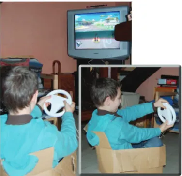
One of the goals of Human–Computer Interaction is to reduce the gaps between users and systems [34]. Solutions such as, graphical user interfaces (GUI), advanced rendering, interaction metaphors, multimodality and computer assisted collaborative tools have been widely studied. However, recent advances in sensors, communication technologies, miniaturization and computing capabilities have led to the emergence of new interaction forms that further reduce these gaps. These new interaction forms rely on the combination of the physical and digital worlds in order to take advantage of computing capabilities and of users’ abilities to manipulate objects within their physical environment. The well-known Nintendo Wii is a simple example of such systems. For example, in the Wii Mario Kart game, (seeFig. 1) the young user is driving a digital car on a digital road. Instead of pressing buttons on a game pad, the user handles a physical steering wheel. Several sensors detect the motion of the steering wheel and translate it into a set of digital commands to be applied to the digital car. To further increase the immersion in the physical world, one can even chose to sit in a carton to simulate the car itself!
Different terms are used to depict these complex forms of interaction such as augmented reality systems, tangible user interfaces (TUI), or even pervasive systems. In this paper, we adopt the general term ‘‘Mixed Interactive Systems’’ (MIS) to refer to these systems. MIS are defined as interactive systems in which users interact with a digital system and involve the manipulation and/or perception of physical artifacts. Appropriate devices, like sensors and actuators, interpret events occurring in the physical layer, translate these events into the digital domain and report to the users the results of the computations through a physical layer. MIS therefore form a class of interactive systems that comprises all the different combinations of digital and physical worlds [13].
Historically, Mixed Interactive Systems were initially targeted at specific, highly demanding and constrained application domains such as surgery [28], air traffic control [30] and even military applications [32]. However, these interaction forms are now found in a large set of application domains (e.g. arts, knowledge transfer, communication, marketing) and have largely demonstrated their potential benefits [43] from end-users’ perspective. To face this growing interest and to ease the understanding and implementation of these interaction forms, efficient development resources are required. These are essential to effectively support the development of MIS, i.e. their design, implementation and evaluation. However, compared to traditional interactive systems based on the screen/mouse/keyboard paradigm, these interaction forms are tremendously complex and implies new challenges. Indeed, Shaer and Jacob [42] underline that ‘‘designing and building a TUI1
requires cross-disciplinary knowledge’’ and argue that due to the intrinsically complex nature of these systems, ‘‘developers face several conceptual, methodological and technical difficulties’’.
This complexity is mainly due to two aspects:
•
Interaction design is no longer confined to desktop environments.•
Additional dimensions need to be considered.For example, the presence of physical artifacts, the strong links between physical objects and digital data implied by MIS and the variety of devices and technology must be addressed. Consequently, suitable development resources have been developed. On one hand conceptual taxonomies and models [24,47,11] have been defined to understand mixed interactive situations, the elements characterizing them and their properties. On the other hand, software toolkits and frameworks [22,25,13], rapid prototyping environments [10] or runtime platforms [4,26] have been proposed to structure the implementation of MIS. These two sets of development resources cover the relevant aspects of the development of MIS. However, these two complementary resources (i.e. design model/taxonomies and toolkit/framework) still remain highly separated, thus creating a gap between early design specifications and implementation considerations. Indeed, concrete and systematic links have not been clearly expressed between high-level design models and implementation frameworks.
In this context, combining and taking advantage of these two type of resources, i.e. the set of abstract supports for the design and the set of concrete supports for the implementation, would ensure a more efficient support to the development of MIS. First, development time could be reduced through the reuse of components thus rationalizing the design options. Then MIS potentials could be more systematically exploited thanks to a clarification of MIS concepts and specificities . Finally, possible automation of parts of the development would be more easily identified. Our contribution to a more integrated development of MIS aims to bring these perspectives together by adopting a Model-Driven Engineering (MDE) approach. Indeed, MDE promotes the interconnection of models through the use of mappings and transformations [18] and relies on the definition of metamodels, each of them carefully describing a model, i.e. a specific point of view of the system.
Fig. 1. A young player using the Nintendo Wii Mario Kart in a physically immersed version.
During the last decade, MDE principles have been explored to tackle HCI development issues. Consequently, we first present in this paper a review of the literature, related to previous uses of MDE in HCI. We then focus on five major benefits of MDE particularly relevant to MIS, a specific category of HCI as defined previously in this paper. Among the existing MDE tools and resources we identify and briefly introduce those supporting these benefits: they form the pillars of the success of an MDE-based MIS development approach. Based on this analysis, a detailed presentation of Guide-Me, our MDE-based framework for MIS development, follows. Guide-Me includes:
•
Two complementary Domain Specific Languages (DSL): each one addresses some of the most relevant design and implementation facets of MIS. The goal of these two DSL is mainly to help designers and developers in expressing their choices at different steps of the development process.•
Mappings and transformation mechanisms between these models and component-based prototyping platforms: these mechanisms are required to maintain consistency from design to runtime, through flexible links between models of different design steps.Then, we present a concrete environment based on Eclipse EMF that supports the use of our framework. The different aspects of our framework are illustrated all along the paper on a case study called ‘‘notepad assisted slideshow’’. Finally, we discuss the outcomes and limits of Guide-Me with regards to the five benefits of MDE for MIS, identified at the beginning of the paper. This analysis (i) reveals aspects of an MDE-based development process covered by our framework for MIS and, (ii) supports the identification of future developments of the considered framework.
2. Model Driven Engineering in human–computer interaction
The fundamental principle of Model Driven Engineering (MDE) is that ‘‘Everything is a model’’ [5]. When developing a system, several models are instantiated to describe different points of view on the system. For each point of view, i.e. a model, a metamodel defines the model‘s rules and syntax. In addition, model transformations are used to systematically link several metamodels. For example, when developing an interactive system, high-level design models and software code are different representations of the same system. MDE approaches and tools have been successfully used to obtain a final system implementation from conceptual and abstract models. However as underlined in [49], most of the MDE experiences focus on the design of ‘‘the functionality and persistency of Information Systems [. . . ], pushing into the background the UI modeling’’. And yet, HCI plays a large role in the design and acceptability of software systems.
Therefore, the HCI community has also worked at developing the use of models during the design process. HCI design approaches relying on the use of models are known under the generic term of Model Based User Interface Development Environments. Among them, one of the earliest works established a link between the data type structures required by the application and the widgets used in the layout to present and manipulate the data [19]. As a result high level specifications were transformed into runnable code which contributes to more rapid development process. Following the successful use of MDE principles in different contexts, such as multi-platform systems, dynamic web applications or reverse engineering, HCI design approaches relying on models also explored the benefits of advanced and structured MDE resources. In the following sections, we illustrate this trend by synthesizing existing MDE attempts in the field of HCI. We have structured
our review according to two main usages of MDE in HCI: (1) a support for the implementation and (2) a support for the system adaptation.
2.1. MDE for supporting HCI implementation
The first category of work exploring MDE in HCI, aims to offer support to the implementation based on specifications expressed in different models: different abstraction levels of a system are thus combined. These approaches promote a distinction between Platform Independent Models (PIM), used to describe different design considerations, and Platform Specific Models (PSM), used to describe aspects of the concrete software implementation. PSM are thus highly dependent on the implementation platform. Among them, PervML [41] is an extension to UML that takes into account the specific facets of pervasive systems, especially the services and communications involved. Using transformations, each PervML model is mapped to OSGI platforms. This approach manages the heterogeneity of interaction techniques by promoting modularity and reusability. However, the modeling resources implied are system-centered and thus user-centered considerations are difficult to consider into this MDE process. Furthermore, no mechanisms are proposed to integrate design choices during transformations, limiting the developers’ interventions.
The distinction between PIM and PSM is also present in numerous works that are not affiliated with MDE approaches. They use markup languages linked together with MIS development toolkits. For example, an extension of the User Interface Markup Language (UIML), the CUIML schema [39], is used in DWARF, a platform dedicated to the prototyping of Augmented Reality systems. Similarly, the APRIL schema [29] associated with the Studierstube SDK, and the MRIML schema [50], enable the creation of models to configure platforms and to generate a description of the interaction technique. APRIL and MRIML use XSLT and generate Virtual Reality Markup Language (VRML) or HTML. The use of markup languages such as XSLT, VRML and HTML offers a high level of abstraction (as opposed to code), but the underlying architecture remains specific to a dedicated platform. Conversely, approaches such as WComp [10] or Open-Interface [36] adopt a highly generic approach to describe the software and are not limited to a set of specific technologies as Studierstube does with marker-based video recognition input or VRML rendering.
In terms of implementation, additional considerations at higher levels of abstraction are also relevant and have applied MDE approaches. For example, the FIIA framework proposes a metamodel with conceptual and distribution levels [51]. By linking these two levels using a specific transformation engine, FIIA assists the development of distributed and collaborative systems. Therefore, FIIA does not particularly focus on user interaction, but highlights the helpfulness of MDE for distributed computing considerations, a complementary facet of interactive systems.
Although these approaches play a role in the insertion of HCI considerations into an MDE-based design process, they do not clearly support the entire design process. Indeed, only specific steps of the design process are covered such as the generation of running applications or the distribution over the network. Some rare attempts seek to cover the whole design cycle of HCI with an MDE-based approach: this is the case of Teresa [33] and the TOOD+ approach [31]. However, these two approaches have the severe drawback that the models used at each step of the design are specific to the approach. Only Concur Task Tree (CTT) model [37] can be used with Teresa and, TOOD+ recreates its own set of design models for each step. In addition, no concrete mechanism is described or offered to link these approaches with other models: links between the different models involved are hard-coded in the environments. TERESA and TOOD+ thus appear as universal ‘‘black boxes’’ to be used to design HCI with a MDE-based design process. As a result, designers are no longer free to use their preferred models in the analysis, design or implementation steps, and are forced to use those provided by the approach.
2.2. MDE for supporting HCI adaptation
The second category of works exploiting MDE in HCI is related to the adaptation of systems. Such works take advantage of MDE principles in order to generate multiple but coherent versions of a unique application [7]. For example, an application involving the famous triptic screen/mouse/keyboard could be derived in a first version executed on a desktop-based device and. Simultaneously, the same application could be derived in another version running on a smartphone and thus involving adapted interaction resources such as a smaller screen and multi-touch input.
More recent works in this area are intended to manage this sort of adaptation at run-time. These systems are commonly known as plastic and context-sensitive interactive systems [46]. With such interactive systems, tasks, devices, dialog, users’ abilities, etc. are taken into account at run-time to dynamically adapt the structure and/or appearance of the interactive system. To do so, these systems are defined as a set of models and mappings between them. In addition, to support run-time adaptations, models and their relationships change dynamically at run-time: changes in one model at run-time affect the other models and the behavior of the system; transformations implied can either be parameterized with ergonomic rules or controlled by the user [46]. These works also provide explicit metamodels, mappings and interactive transformation mechanisms of great interest to the HCI community.
2.3. MDE in HCI: outcomes
To summarize, the earliest approaches of MDE in HCI design focused primarily on direct translations from abstract models to code. This is fully in line with HCI design approaches. Indeed user’s centered questions such as requirements,
tasks, goals or preferences are prevalent when developing interactive systems and allow developers to reason about the system without placing an emphasis on code and technological preoccupations too early in the process. Further evolutions of the use of MDE in HCI have been influenced by the kind of models used. Although UML is a well established reference in terms of models, and offers multiple diagrams to address different aspects, it is not sufficient to describe HCI aspects: too little attention is paid to the users, their activities and their relationships with the system. As a result, the HCI domain has progressively developed models to specifically address its central dimensions: MDE in HCI was no longer limited to the use of UML diagrams. Finally, the latest use of MDE in HCI aims to have models co-existing with the running application. This allows for dynamic adjustments of the application’s behavior, even for non-experts in the field of programming languages. The Cameleon framework [8] reconciles and structures these different approaches through the identification of four design levels: final UIs are considered as a PSM, while three other levels identify different forms and places of possible adaptations at a PIM level.
It therefore appears that MDE gradually contributes to explicit specific metamodels in HCI engineering. In addition, established mappings between these metamodels help HCI designers to provide an understanding of the relationships between models and to specify their adequacy for different development steps. But HCI is still evolving, continually discovering new and more advanced forms of interaction. Adaptations in the development process are thus required and the way MDE is used for advanced HCI must continue to evolve.
To anticipate and support these evolutions, we have identified several aspects of MDE that are particularly relevant to the field of HCI. Among these aspects, five were identified as crucial for the design and engineering of Mixed Interactive Systems (MIS) [21]. The following section briefly defines these five aspects, highlighting their value for the development of MIS and placing these benefits within the MIS development process.
3. Model Driven Engineering (MDE) benefits for Mixed Interactive Systems (MIS) development
MDE has proven its usefulness to the field of HCI, especially because of the tools, methods and mechanisms included in MDE. Among the benefits of MDE to HCI, five appear particularly valuable, relevant and useful for MIS. In particular, MDE is useful for:
1. Identifying and characterizing the entities 2. Generating multiple representations
3. Constructing, maintaining and manipulating a graph of models 4. Structuring the development process
5. Supporting the integration of design decisions
For each of these five benefits, we briefly summarize its role and illustrate it. We then elaborate on the anticipated benefit it provides for the development of advanced forms of interaction such as MIS. Further discussions about these selected benefits can be found in [21].
3.1. Benefit 1: identifying and characterizing entities
HCI design relies on the use of multiple models, each of them focusing on different design considerations. In the previous section, we highlighted that adopting MDE for designing HCI facilitates the use of these multiple models. Indeed, each model constitutes a specific point of view of the system and therefore deals with a set of specific concepts present in the interactive system. It is therefore a prerequisite to provide an explicit description of each concept, i.e. a well identified and relevant set of attributes. Models will act as a reference language and ensure a unified representation and correct understanding of the system. When using MDE approaches, metamodels help to identify and characterize the entities that are potentially involved in the system. Metamodels also provide explicit semantics and syntax for supporting the diffusion of models. Indeed they can be seen as a detailed legend of the concepts used in the model (name, type, hierarchy). As a result, metamodels serve as a unique reference for understanding the language used to describe the system.
In the context of MIS development, metamodeling is thus the key activity to clarify the intrinsically complex nature of MIS, the semantics and the role of the multiple entities involved. Each metamodel will serve to establish a solid reference language for describing MIS.
3.2. Benefit 2: generating multiple representations
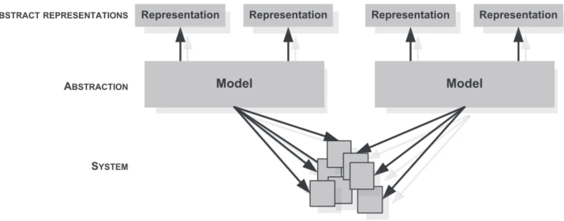
In the existing approaches using MDE to produce code from abstract specifications, many solutions generate runnable programs and simultaneously provide a diagrammatic representation of the software components, ports, events and exchange of data. However, the development process generally involves different stakeholders who are used to manipulating different representations. The use of MDE approaches thus offers the possibility of generating multiple representations of a unique model (seeFig. 2). XML, HTML, textual, graphical, partial or detailed views and automatic documentations can be easily derived with the help of existing MDE automation resources.
Because developing MIS is intrinsically a multidisciplinary activity, offering the most appropriate representations to each stakeholder will facilitate the building of a common understanding of the system and so ease collaboration and decision-making.
Fig. 2. Using models to easily link different views of a system and the concrete system itself.
3.3. Benefit 3: constructing, maintaining and manipulating a graph of models
The design of interactive systems, which automatically adapt at runtime, reveals the need to simultaneously combine multiple models to make decisions. A modification in one model may potentially impact all other models. Graph of models have been used in particular to express which ergonomic properties are preserved through a link [45]. To support such a requirement, MDE resources provide different supports for constructing, maintaining and manipulating a graph of models. More concretely, such supports include tools and mechanisms that explicitly highlight and characterize the relationships and dependences between models [12]. In graphs of models, nodes usually represent models, while arcs express the presence of a link (e.g. a transformation) between two models and its properties (e.g. preserving or not specific ergonomic criteria).
Developing a MIS requires to manage simultaneously multiple considerations, all along the development process. A graph of models will thus be highly supportive for MIS design and implementation to provide a complete overview on the relevant models and their mutual impact. In addition, given the multiplicity of existing models developed to cover parts of MIS design, the presence of cycles in graphs of models will also be useful to highlight equivalent design paths, based on different models, but covering the same design aspects of MIS. Choosing one cycle, i.e. one set of models, rather than another may then rely on how familiar the designer is with the proposed sets of models.
3.4. Benefit 4: structuring the development process
HCI design activity traditionally iterates through four phases: analysis, design, prototyping and evaluation. Each phase involves different models and has to consider and integrate decisions taken in previous phases. Through the explicit definition of transformations between models, MDE approaches help to structure the development process of interactive systems. Source models and target models of a transformation may be part of different design phases; implicitly the transformations create the dependency and sequence order between two design models: they orient the arcs in the graph of models.
MIS are just a specific and more complex form of HCI. Structuring their development is even more relevant since a wider range of decisions, related to different facets of the MIS, must be taken before going to the next steps.
3.5. Benefit 5: supporting the integration of design decisions
Finally, developers must take into account design decisions adopted earlier in the development process. Using MDE provides strong support for the integration of design decisions throughout the development process. Indeed, as we have mentioned, MDE transformations structure the order in which different design resources are used. They can also be productive and therefore drive the translation from one step to another and therefore contribute to maintain the consistency in the graph of model.
This benefit will largely support the development of MIS because early and original design considerations, specific for example to physical characteristics, will be easily integrated into software design reasoning.
3.6. Overview of a MIS development process integrating MDE benefits
To summarize these five benefits, it appears that MDE brings two core elements to the development of MIS. The first core element is a detailed description of elements composing a MIS. As identified in benefit 1, metamodels clearly identify and characterize entities involved in the system. The second core element is a scaffold structuring the use of the different relevant models. As expressed by benefit 4, model transformations implicitly highlight dependencies between models, thus structuring their use and the design process.
Fig. 3. Integrative illustration of the place of the five MDE benefits in a MIS development process.
Fig. 4. Operational MDE resources, roles and associated benefits for the development of MIS.
Those two core elements are instrumented by MDE’s additional abilities. First it supports the production of multiple representations of a metamodel. As underlined in benefit 2, information that are conform to a metamodel can easily be rendered through different predefined format. Second, it offers transformation mechanisms. As depicted in benefit 5, such mechanisms contribute to integrate design decision all along the design process.
Finally an MDE approach offers an overview of the development process of MIS through the notion of graph of models (benefit 3) that groups and articulates the two core elements (metamodels and structure) and the identified MDE abilities (multiple representations and transformations). This summary is illustrated inFig. 3.
In the previous sections, we emphasized, from a theoretical point of view, which benefits have driven the successful use of MDE for the development of HCI and advanced forms of interactive systems such as MIS. In the following section, we focus on a practical point of view and identify which MDE resources may be useful to concretize each of these benefits. We then build a generic overview of an MDE-based development process for MIS through which we emphasize the set of relevant resources as well as their role.
4. MDE resources supporting MDE benefits
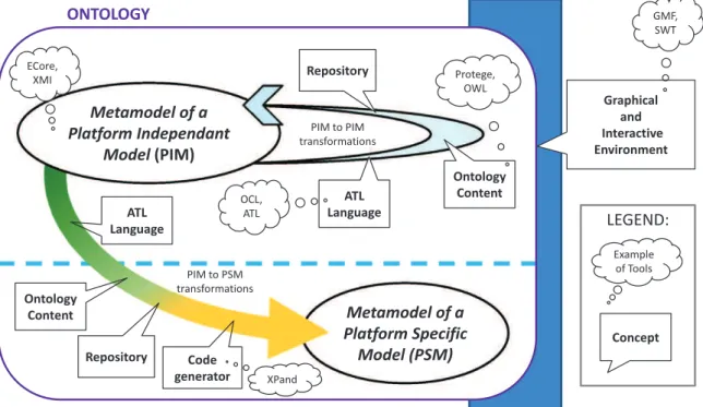
As mentioned above, MIS developments may take advantage of five major benefits of MDE approaches. Among the rich and evolutionary set of tools, languages and mechanisms proposed in MDE, we have identified a subset of MDE resources that can effectively cover these benefits: this subset of resources is the key to the successful use of MDE for the design and engineering of MIS.Fig. 4summarizes these MDE resources and the remainder of this section details their role with regard to the five benefits identified.
To clearly identify and characterize entities involved in a MIS (Section3.1), models and their corresponding metamodels are the first cornerstones of the introduction of MDE in MIS development. The Eclipse Modeling Framework (EMF) offers appropriate features to effectively develop metamodels. In particular, EMF Ecore allows the creation and editing of class diagrams, in which a class depicts a type of entity. A class includes attributes and can be connected to other classes through dependency, inheritance or composition links. EMF Ecore also includes pre-existing primitive types such as EInteger, EString, EDate. In addition, ECore diagrams enable the graphical editing of class diagrams representing metamodels. Finally XMI is the underlying format for storing and exporting class diagrams.
To support model editing, that maintains conformance with the metamodel, GMF2and SWT3provide strong support
for generating a graphical editor. They offer basic features for displaying, modifying and saving a model with respect to its metamodel syntax and semantic. The resulting editor is integrated in the Eclipse environment as a specific plugin. Through this editor and its basic functionalities, multiple forms of rendering can easily be derived. At a minimum it provides the designer with textual or graphical representations, but it also facilitates the implementation of more advanced features such as the generation of HTML pages or the adoption of different views on the model. This contributes towards the second benefit of MDE to MIS development, offering the possibility of generating multiple representations (Section3.2).
As mentioned before, the creation of different metamodels is crucial for covering the different design aspects of MIS. To do so simply relies on creating multiple ECore metamodels, and their associated editors. As a result, multiple views are added to the Eclipse environment and can be selected according to the metamodel of interest. With this Eclipse toolset, the main advantage is that all the metamodels and graphical tools for manipulating the metamodel instances are grouped in a common environment instead of requiring a multitude of standalone applications. This MDE facility therefore contributes to satisfying the third benefit of MDE to MIS development, constructing, maintaining and manipulating a graph of models (Section3.3).
Structuring the development process and supporting a better integration of design decisions in subsequent development phases rely on the second cornerstone of MDE: transformations. In fact, without them, all the models would be isolated. The first type of transformation consists of mapping elements (e.g. entities, attributes, associations) of a source metamodel to elements of a target metamodel. Consequently it transforms abstract models (Platform Independent Models, PIM) into Platform Specific Models (PSM). ATL (ATL Transformation Language) is one language among several that allows the definition of rules to specify the mappings. In conjunction with ATL, an algorithm using OCL (Object Constraint Language) operations implements the transformation rules. It defines the behavior that must be applied according to the values of the source attributes/elements. Later in the development process, such mappings target the code generation. To do so, languages such as XPand, are specialized in code generation based on EMF models. It creates the envelope of the software component, i.e. its signature. Therefore mappings define an order in which different metamodels must be considered along the development process and thus help to structure the development process (Section3.4). The content of the transformation, i.e. the rules translating an element from a source metamodel into an element of a target metamodel, goes even further and concretely ensures that design decisions are well considered in further steps of the development process (Section3.5): they trigger the creation of specific elements of one of the subsequent metamodels used along the process.
However designing advanced user interfaces requires adjusting the design, fine-tuning the solution: this can only rely on human expertise. Monolithic code generators and straight model translators are not sufficient; human intervention is required during the transformation to allow the designer to manually provide additional information. The second type of transformation addresses this requirement and complements basic mappings. The goal of these advanced transformation mechanisms is to handle small, reusable and extensible parts of the transformations. The global transformation is thus split into subparts; the designer can interact at each level and select a solution from several propositions built through the transformation process; the designer can also, if necessary, adjust the most appropriate transformation result. The result of the transformation can then be added to a library for further use. In this way, expertise can be captured and packaged into transformation libraries. Enhancing the reusability of such elements is a second way to promote the integration of design decision into the development process. Two complementary tools offer such features. The first tool consists of an ontology used as an input to transformations. For example Protégé [38], an ontology editor, is fully compatible with the ATL transformation language. Indeed, Protégé allows the querying of the ontology in the definition of the transformation rules. The execution of the transformation rules thus takes advantage of the knowledge saved in the ontology to perform the transformation. Conforming to the OWL metamodel, a Protégé ontology contains links between instances of an attribute (or a set of attributes) from a source metamodel and instances of an attribute (or a set of attributes) in a targeted metamodel. A so-called repository is a second tool that complements this knowledge base: it stores the concrete and complete descriptions of an already existing solution expressed in a model. These advanced transformation mechanisms thus strongly support the integration of design decisions in subsequent design steps (Section3.5): elements of the source model are more precisely and completely taken into account and elements of the target model can be more precisely defined thanks to the ontology content.
To complement the view provided inFig. 3on the place of the benefits of MDE in the MIS development process,Fig. 5
summarizes the roles of the MDE tools and thus highlighting the part of a MDE-based development process to which each of these MDE tools and resources may contribute.
In the remainder of this paper, we present the Guide-Me Framework. Guide-Me is a concrete instance of this structured and generic overview of the MDE-based development process for MIS, introduced in the previous sections. The goal of this concrete instance is to take advantage of (1) the benefits of MDE for MIS, (2) their place in a design process and (3) the role of MDE tools and resources in a design process. The Guide-Me framework, available online [23], its metamodels, transformations and other resources are introduced and illustrated in the following sections.
2 GMF: Graphical Modeling Framework;http://www.eclipse.org/modeling/gmp/. 3 SWT: Standard Widget Toolkit;http://www.eclipse.org/swt/.
Fig. 5. Generic overview of an MDE-based development process for Mixed Interactive Systems and appropriate MDE resources.
Fig. 6. Concrete components of the Guide-Me framework and link with the five benefits of MDE for MIS design and engineering.
5. Models involved in the Guide-Me framework
To instantiate the overview given inFig. 5of an MDE-based process for the development of MIS several metamodels are required. Among the multiple design models that have been proposed in the field of MIS, Guide-Me is composed of three main metamodels. The ASUR metamodel [21] describes the interaction level with a user-centered perspective. Rather than focusing on the technology used or a specific facet of the system, it provides a detailed overview of the interaction that takes place between the user and the different elements of the system. To fill the gap between such an abstract view on the system and its concrete implementation, a complementary metamodel is used: ASUR-IL provides support for expressing design decisions related to the software architecture and the implementation underlying a MIS. Finally, WComp [10] is a component based runtime platform used to produce the running application.
The framework also includes mappings and transformations to guide the designer from abstract interaction design to concrete software implementation.Fig. 6summarizes the content of the Guide-Me framework and conforms to the diagrammatic representation provided inFig. 3 to express how Guide-Me takes advantage of the MDE benefit in a MIS development process. The following sub-sections detail and illustrate the metamodels. The transformations are described and illustrated in Section6.
To illustrate the content of our framework, we first present the ‘‘notepad assisted slideshow’’, a MIS development case study.
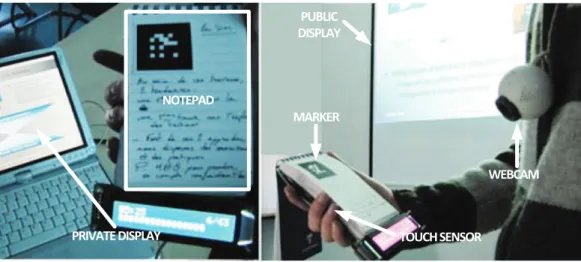
Fig. 7. Use of the ‘‘notepad assisted slideshow’’.
Fig. 8. Main elements of the ASUR metamodel.
5.1. The ‘‘notepad assisted slideshow’’
For oral presentations, sequential slideshow systems like PowerPoint are commonly used. The prototype we have designed is a physical enhancement of such a slideshow system. It involves a notepad as a ‘‘remote control’’ and provides several feedbacks. Each page of the notepad is linked to one digital slide (seeFig. 7). When using this prototype, the speaker opens the notepad at the page corresponding to the slide s/he wants to display to the audience; the speaker can thus write his own comments on the notepad and easily access the corresponding slide. An additional feature supports the standard animation steps mechanism: each tap on the notepad advances the slide animation by one step.
The interactive solution we have developed is based on the use of a webcam combined with a fiducial marker based detection API. As shown inFig. 7, a marker is printed on each page of the notepad. Each marker corresponds to a notepad slide number. When captured by the webcam and recognized by the system, the corresponding slide is displayed through a video-projector. In addition, a touch sensor detects the user taps used for advancing the slide animation. Finally, a private display is provided to the speaker on which private information is displayed (slide, time elapsed, remaining slides).
This design solution has been conveniently chosen to illustrate the most relevant aspects of our framework; it does not ensure that the chosen design is the most usable one. It rather demonstrates how design decisions expressed in the earliest design stages are forwarded in the subsequent development steps.
5.2. ASUR: modeling a Mixed Interactive System
ASUR aims at describing the user’s interaction with a MIS. It stands for Adapter, System, User and Real world. As introduced and justified in its first definition [15] the ASUR metamodel includes four corresponding types of entities (see left side ofFig. 8): Adapters which bridge the physical and digital worlds, System depicting the digital entities involved in the system, the User of the system and Real objects taken from the physical world and involved in the interaction. Each of these entities may interact with the others through interaction channels (
→
): these relationships denote existing informationexchanges when using this interactive system.
The latest evolution of ASUR [14] refines the concept of relationships between entities and channels (see right side of
Fig. 9. ASUR modeling of the ‘‘notepad assisted slideshow’’. Dotted lines emphasize the four layers corresponding to the four main kinds of ASUR
components (Adapter, System, User, Real object) mentioned in the legend (left of the figure).
Fig. 10. Interaction between the speaker and its notepad.
emitter, a channel and a receiver. The emitter (modification method
⊙
) expresses the way an entity affects a channel and the receiver (sensing mechanism⊗
) expresses the way the targeted entity senses the channel state. A channel is established between them and is characterized by a medium (e.g. light, physical contact, infrared, air). Finally, a representation expresses the coding scheme used on a channel and is principally characterized by the dimension and language form of the data. These elements are part of the ASUR metamodel [21] and are also illustrated inFig. 8.In the case of the ‘‘notepad assisted slideshow’’, the corresponding model is diagrammatically represented inFig. 9. The ASUR diagram should be read as follows: the ‘‘User’’ (U) selects the pages of the ‘‘notepad’’ (R). Each page is detected by an adapter ‘‘PageDetector’’ (A). In addition, the ‘‘User’’ (U) may click on a second adapter ‘‘StepDetector’’ (A) to animate the slide. These two adapters deliver digital data to the ‘‘Slideshow’’ (S). The Slideshow provides the data contained in the current slide. Finally, the state of the slideshow is rendered through two different adapters (A), the ‘‘Private Display’’ and the ‘‘Public Display’’ respectively providing information to the ‘‘User’’ (U) and the ‘‘Attendees’’ (U).
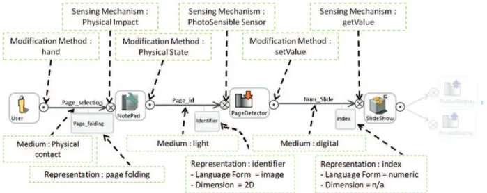
Fig. 10shows only a subset of the ASUR model used in our case study, in order to show the attributes of an interaction channel that are not visually represented on the ASUR diagram shown inFig. 9. For example, between the Notepad (R) and the PageDetector (A), the information that is sent is the ‘‘page_id’’. The medium used by the interaction channel (the arrow) to carry the information is ‘‘light’’. The modification method (the circle on the left, with a dot) is set to physical state: it expresses how the source entity affects the medium. Conversely, the sensing mechanism (the circle on the right, with a cross) is set to ‘‘photoSensible Sensor’’: it describes how the information on the medium is captured by the target entity. The representation (i.e. the gray square below the interaction channel) of the information carried through the medium is an ‘‘identifier’’, characterized by a language form set to ‘‘image’’ and a dimension set to ‘‘2D’’.
The ASUR metamodel [21] provides a concise and structured definition of these different elements. Other design considerations, such as the notion of grouping mechanisms, can be expressed with the ASUR metamodel but have been omitted in this paper for sake of clarity. As illustrated above, ASUR can be used in a graphical form or in a textual way using a markup language. With ASUR, the early phases of MIS design are supported and then influence the next phase of
Fig. 11. Main elements of the ASUR-IL metamodel.
the development: the implementation. Finally, previous works also demonstrated that ASUR is understandable for non-experts [6].
5.3. ASUR-IL: modeling an abstract mixed interaction software architecture
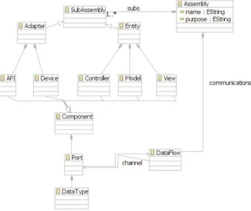
The ASUR-Implementation Layer (ASUR-IL) model is meant to describe software architecture considerations supporting the implementation of the system. To express this software oriented point of view, ASUR-IL first exploits the core concepts of component-based architectures, as expressed by ACME [20]: component, port (◮) and data flow (
→
). This low level specification in ASUR-IL is crucial because technologies used in MIS may require different runtime platforms. Component-based architectures constitute a well-known support to guide several implementation technologies.Given that ASUR-IL is targeted at interactive systems, this model also conveys the software architecture properties of interactive systems. As expressed in the Arch model [3], there is a clear distinction between the functional core and the interaction supports. As a result, the metamodel includes two different forms of ASUR-IL sub-assemblies: on one hand an
entity sub-assembly represents system-dependent components constituting the functional core of the system; on the other
hand an adapter sub-assembly represents system-independent components, in charge of the interaction management. However, those sub-assemblies need to be broken down further in order to make them easily understandable and reusable. For that reason an ultimate break down level is applied to each ASUR-IL sub-assembly and expressed in the metamodel.
Entity sub-assemblies adopt the MVC pattern [27]. They are broken down into three parts, a Model, a View and a
Controller. This breakdown promotes a clear distinction between elements of the functional core (the Model, M), actions
on these elements (Controller, C), and information rendering of these elements (View, V). Adapter sub-assemblies follow the Arch model breakdown of interaction techniques by separating physical and logical interaction components. Adapter sub-assemblies thus contain two types of components named device ( ; ) and API ( ). An API constitutes a software abstraction of the data provided by a device and therefore contributes to the independence of the system with regards to the technology used; an API also increases the reusability of software components. These two high level breakdowns are especially relevant when involving heterogeneous interaction modalities: it is therefore interesting to keep a separation of roles (model, view, and controller) and abstraction levels (device, API) in addition to the modularity and reusability introduced by Arch and MVC.
These elements of the ASUR-IL metamodel are summarized in the graphical representation of the metamodel (seeFig. 11). We now illustrate its use in our case study, and draw a parallel to the ASUR model to facilitate understanding.
In the case of the ‘‘notepad assisted slideshow’’, entities of the physical world are not represented in ASUR-IL: obviously, with physical objects, no software consideration has to be refined. From an interactive software design point of view, the left side ofFig. 12illustrates the ASUR-IL input adapter sub-assemblies corresponding to the ‘‘page detector’’ (A) and the ‘‘step detector’’ (A) previously expressed with ASUR (seeFig. 9). For each one, a device is identified to capture the input information and an API has to be instantiated to transform it into a compatible data type. As a result the combination of the ‘‘PageSensor’’
Fig. 12. ASUR-IL modeling of the ‘‘notepad assisted slideshow’’. Below the figure the major elements of the ASUR-IL metamodel are shown: adapter made
of devices and APIs, entity made of model, views and controllers.
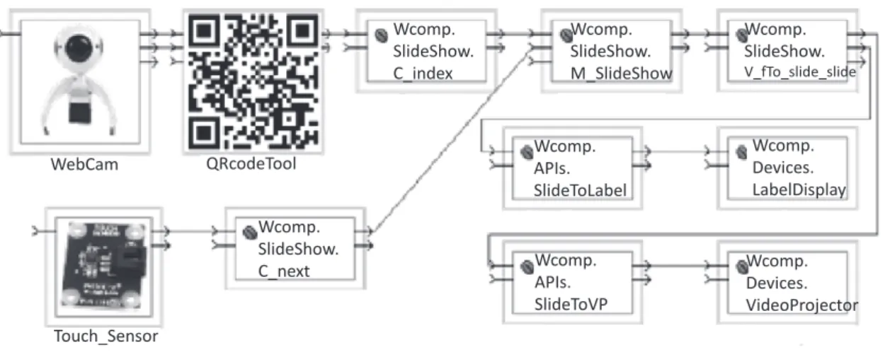
Fig. 13. WComp software components assembly corresponding to the implementation of the ‘‘notepad assisted slideshow’’.
(Device) and the ‘‘id_extractor’’ (API) constitutes the first ASUR-IL adapter sub-assembly. Similarly the right side ofFig. 12
depicts the ASUR-IL output adapter sub-assemblies corresponding to the private and public displays (A) identified in the ASUR model. In-between the adapter sub-assemblies stands the ASUR-IL entity sub-assembly which corresponds to the ‘‘slideshow’’ (S) expressed in ASUR. This sub-assembly involves four components: two controllers (one for each incoming data), one model and one view that groups all the data required to render the current state of the slideshow. From a software point of view, each roundedsquare corresponds to a software component; triangles denote ports and arrows represent data flows. An ASUR-IL model of the ‘‘notepad assisted slideshow’’ (seeFig. 12) thus provides a software point of view on the design solution expressed with ASUR inFigs. 9and10.
5.4. WComp: a platform specific (meta) model (PSM)
Currently a third metamodel is used in the Guide-Me framework: WComp [10], a Platform-Specific Model (PSM). The WComp editing environment is made of Containers and Designers. Containers provide non-functional services required by components of an assembly at runtime (instantiation, destruction of software components and connectors); Designers manipulate and adapt component assemblies. WCOMP offers a repository of software components which are classes with specific properties and events. As a result, each new component must be implemented by a developer. The components’ connectors represent their available inputs/outputs. To interconnect two beans, the data types associated to their connectors have to be compatible.
In the case of the ‘‘notepad assisted slideshow’’, software components and their connections correspond to the assembly shown inFig. 13. Each gray link represents a link and each box with ports on their border depicts one independent software component. From left to right, the assembly depicts the use of the WebCam device (PageSensor in ASUR-IL modelFig. 12)
linked to a QRcodeTool API. This API is linked to the controller C_index. Below, the device Touch_Sensor (d_StepDetector inFig. 12) is linked to the controller C_next. Both controllers are linked to the model component (M_SlideShow) which is linked to the view (V_fTo_Slide_Slide). Then two links start from the view and are bound to different APIs (SlideToLabel and SlideToVP). Each API is related to one display component (LabelDisplay and VideoProjector). These display components implement the private and public displays expressed in the ASUR model (cf.Fig. 9). Clear links are thus identifiable between this software view and the previous design views on the same system.
5.5. Discussion: concrete metamodels and MDE benefits
Regarding the specificities of the Mixed Interactive System domain, the two first metamodels (ASUR and ASUR-IL) allow the capture of the most relevant considerations and as a result supports designer reasoning about specific aspects of MIS. For example ASUR-IL modeling forms a bridge between ASUR elements and a component-based implementation with WComp; it also contributes to the description of a software architecture which is independent of the prototyping environment used by the developers.
From the point of view of the MDE benefits for MIS, ASUR and ASUR-IL metamodels provide a structured and detailed description of mixed interaction (Benefit 1, Section3.1). They also combine different representations, a graphical and a textual notation in our case (Benefit 2, Section3.2). In addition, the ASUR-IL perspective is definitely complementary to the ASUR one, thus clearly separating design concerns. The combined use of these two metamodels therefore helps to support the use of a graph of models (Benefit 3, Section3.3).
However, both ASUR and ASUR-IL models remain at an abstract level and independent from any concrete implementation platform. In order to connect the use of these two metamodels to the development process (Benefit 4, Section3.4), ensure that ASUR design decisions are well taken into account when modeling the system with ASUR-IL (Benefit 5, Section3.5) and create concrete links between these Platform-Independent Models (PIM) and a Platform-Specific Model (PSM) (i.e. the IDE in which the system is ultimately implemented), our framework proposes a set of transformations that are presented in the following section.
6. Transformations involved in the Guide-Me framework
To finalize the concrete instance of an MDE-based development process for MIS (overview given in Fig. 5), model transformations are required. This second set of MDE resources has been integrated into Guide-Me to link the metamodels presented above. This allows us to anchor each development step in prior design decisions and results. With transformations, models become productive. Indeed, they do not simply describe the system but become actors in the development, i.e. playing a prevalent role in the development of the system. Links between models contribute to the co-existence of the knowledge embedded in several models.
Model transformations are composed of rules implying source and target elements. In our case, rules can be of two sorts: – simple mappings between concepts of different models
– more complex operations involving the use of an ontology. Our framework includes two different model bridges:
– from interaction design (ASUR) to software architecture (ASUR-IL), and – from software architecture (ASUR-IL) to a runnable implementation (WComp).
For both bridges, a combination of simple mappings and advanced transformation mechanisms is used. Simple mappings are presented in Section 6.1 and advanced transformation mechanisms, driving the transitions in more detailed, are described in Section6.2. Finally Section6.3presents an assistive transformation which aims to inform the designer with ergonomic recommendations during the manipulation of our models and transformations.
6.1. Simple models mappings: linking concepts of metamodels
We first introduce the mapping between the two abstract models before presenting the mapping with the concrete software components.
6.1.1. ASUR to ASUR-IL mapping
The mappings between these two metamodels are based on the nature of the ASUR entities. First, physical entities such as the user (U) and the real objects (R) do not have any equivalent in ASUR-IL because they do not have to be implemented as software components. Then, for each ASUR adapter (A), the transformation creates an ASUR-IL adapter sub-assembly, containing one physical component (device) and potentially several logical components (API).
Finally, for each ASUR digital entity (S), an ASUR-IL entity sub-assembly is created containing one model (M) component, and one or several view (V) and controller (C) components. The number of views and controllers is driven by the interaction
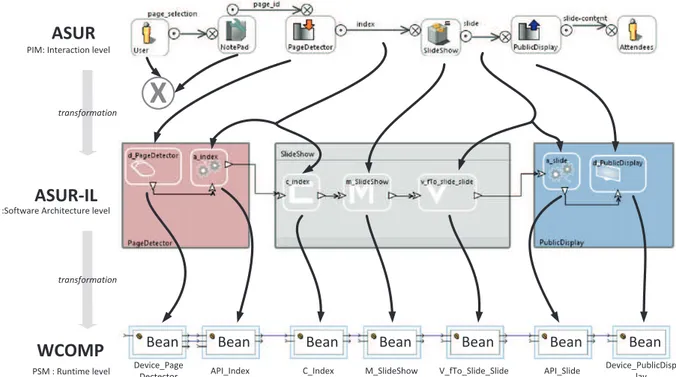
Fig. 14. Illustration of ASUR to ASUR-IL and ASUR-IL to WComp mappings on the ‘‘notepad assisted slideshow’’.
channels connected to each ASUR entity. Indeed interaction channels constitute an additional source of information to perform the transformation of an ASUR model into an ASUR-IL model:
– Sensing mechanisms and modification methods are used to create and characterize controller and view components, – Medium of a channel is used to create and characterize the corresponding device,
– Dimension and language form of a channel are used to create and characterize the corresponding API component. In the case of the ‘‘notepad assisted slideshow’’, two ASUR-IL input adapter sub-assemblies result from the transformation of the two ASUR input adapters (A). Similarly two ASUR-IL output adapters are generated due to the public and private displays (A) in the ASUR model. Finally, the transformation produces only one ASUR-IL entity sub-assembly because the ASUR model involves only one digital entity (S). To refine these five large sub-assemblies, finer ASUR-IL elements are then identified and used to break down the sub-assemblies into devices and API or Model, View and Controller as explained above. For example, the mapping automatically generates a default ASUR-IL device (d_PageDetector) and a default ASUR-IL API (a_index) to break down the ASUR-IL input adapter sub-assembly corresponding to the ASUR pageDetector adapter.
The top part ofFig. 14illustrates this mapping in the part of the case-study corresponding to the page sensing (step detector is left apart for clarity reasons). It particularly highlights the important influence of the attributes of different ASUR elements and the fact that the user and the physical notepad have no equivalent in ASUR-IL.
6.1.2. ASUR-IL to PSM mapping
Our transformation from ASUR-IL to WComp metamodels is implemented as trivial mappings. These mappings mainly rely on the three concepts of component, port and data flow.
As shown on the bottom part of Fig. 14, in most cases, an ASUR-IL component will be transformed into one WComp software component. Its component signature (input/output interface) is necessarily conforming to the ASUR-IL specification (port, data type). However, the resulting component can either be an existing component or a new one to create. In the first case, the component has to be chosen from the set of already implemented components. In the second case, the component can just be partially generated by the transformation. Only the structure of the component is generated with respect to the expected signatures. The implementation of the component behavior remains the developer’s responsibility. As a result, a set of WComp components (fully implemented or just skeleton) is identified and the transformation is also in charge of creating the appropriate connections between those WComp components. The transformation therefore ends with the creation of a WComp assembly containing the chosen or partially generated components and the links between them.
6.2. Advanced model transformations: using an ontology
For many reasons, such as performance, reliability or usability problems, further design iterations may lead to the identification and to the choice of alternative solutions such as the use of a different device (e.g. IR camera, Kinect). To
Fig. 15. Ontology excerpt used in the ASUR to ASUR-IL transformation.
ease the identification of multiple solutions and increase the reuse of solutions already considered in past design processes, we have defined an ontology describing a set of solutions linking classes or attributes of the source and target models. The ontology also contains some explicit links between devices and APIs that can be combined.
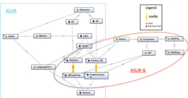
During the transformation, designers have a choice of whether or not to use the ontology. If the ontology is used, designers may select from several solutions suggested by the ontology. For instance, properties of an ASUR interaction channel (medium, dimension and language form) influence the identification of ASUR-IL devices and APIs. Therefore, on the basis of these ASUR properties, the ontology is used to determine if existing pairs of device and API components present in the ontology are compatible with the considered values of the ASUR model properties being transformed. Similarly, the ontology assists the transformation from ASUR-IL to WComp.
Fig. 15highlights a compatibility example of the ASUR-IL device ‘‘WebCam’’ with the ASUR-IL API ‘‘QRCodeTool’’. This combination also complies with the description of the ASUR adapter and related channels provided in the interaction design model: medium and language forms match the initial design decisions expressed in ASUR (light, image). This pair of ASUR-IL components is therefore one of the solutions proposed by the ASUR to ASUR-IL transformation.
In order to embed the ontology in the transformation mechanism, we developed a repository of existing components for each model. The resulting advanced transformation mechanism constitutes an additional source of information to drive the design process. Indeed,Fig. 15also suggests that the pair of ASUR-IL components (‘‘Camera3D’’, ‘‘PositionExtractor’’) complies with the initial design decisions expressed within the ASUR model, thus offering several possibilities. In this way, transformations do not automatically create one unique solution but let designers chose the model(s) which best fit(s).
6.3. Ergonomic recommendations to inform transformations
The transformations presented above assist the development process of MIS by ensuring that design decisions are well forwarded in subsequent development steps. In order to help developers reason about problems related to the usability of MIS [2], we enriched the transformation with ergonomic recommendations.
Indeed, Guide-Me provides access to a list of ergonomic recommendations called RESIM. When editing a model, a designer can access a repository of Usability Recommendations (UR) dedicated to MIS. Each recommendation conforms to a template composed of the domain, modalities, physical objects used, experimental measures and protocol [9]. The list of recommendations can therefore be sorted by these different attributes [16].
Access to these recommendations is integrated into the Guide-Me model editors. A click on a graphical element of an ASUR or ASUR-IL model automatically raises a set of known recommendations related to this type of element. For example, one click on an ASUR USER displays a list of recommendations related to a user’s task; double clicking on one of them opens a pop-up window with the complete text of the recommendation. Additional options are available to browse and sort the list.
6.4. Discussion: concrete transformations and MDE benefits
Regarding the specificities of Mixed Interactive Systems, these different forms of transformation contribute to the reuse of existing design and software solutions. This is particularly interesting in the MIS context to ease the implementation of solutions combining multiple and diverse sensors and effectors.
In addition, Guide-Me transformations support cross-platform implementations. The ontology we developed allows the use of software components from different platforms, thus supporting interoperability. Interoperability is currently supported in Guide-Me across two implementation platforms, WComp and Open-Interface (OI) [36]. Hence developers can select existing OI or WComp components that best fit the requirements without having to consider any problem of compatibility. The underlying interoperability mechanisms are based on standard communication protocols such as UPnP [48] or OSC [40].
More specific to interaction design, these transformations also explicitly base the implementation on early design decisions that have been understood and formalized by software non-experts. This is particularly relevant to interactive systems design where end-users are involved in the development process. Transformation mechanisms ensure that the participation of end-users is correctly taken into account and integrated into subsequent design steps.
In addition, software structures advocated by human-centered design approach are preserved by these transformations. The resulting running application is thus highly flexible, offering great opportunities to easily move from one interaction modality to another without modifying the core of the application. Our approach is indeed particularly robust to the change of device and API involved.
Finally, the way the transformations are integrated into Guide-Me ensures a smoothness of use. The display of multiple solutions resulting from the transformation process allows the designer to interact with the transformation process. Furthermore, the coupling of the Guide-Me environment with the ergonomic recommendations constitutes another strong benefit of our framework in the development process. The current implementation has been created to provide designers with a set of relevant ergonomic recommendations, but does not constrain them to apply or respect one recommendation more than another.
From the point of view of the MDE benefits for MIS, the simple transformation mappings from ASUR to ASUR-IL allow the automatic generation of a partial ASUR-IL model. This generated model is fully consistent with the initial ASUR model, but will have to be fine-tuned and finalized by the developer. The same applies when mapping the ASUR-IL model to a platform specific model such as WComp. In order to apply these mappings, sufficient information must be expressed in the source metamodel. Mappings therefore drive the development process (Benefit 4, Section3.4), by encouraging the designer to reason about different aspects in an appropriate order.
Finally, if elements of an ASUR model are altered, modifications are taken into account when the transformation mappings are applied. Therefore it induces modifications on the corresponding ASUR-IL models, and subsequently on WComp implementations. In addition, the ontology used in the advanced transformations contributes to increase software component reusability and the generation of multiple solutions. These two aspects of the transformations therefore help to explicitly anchor design decisions in the development process and also strengthen coherence in the design process (Benefit 5, Section3.5).
Beyond these benefits, MDE also includes numerous tools for supporting the exploitation of these metamodels and transformations. The following section briefly introduces the Guide-Me toolset, a graphical environment supporting the interactive use of our MDE-based framework to develop MIS. This toolset has been developed as a set of fully integrated plugins into the Eclipse environment.
7. A tool supporting our MDE-based framework for MIS development
The latest advances in MDE lead to capitalize the results into efficient and modular frameworks and standardized common definitions. We summarize the choices that guided the definition of the toolset supporting our framework and finally present the toolset.
7.1. MDE tools choice
To express each metamodel, the first step consists of choosing the appropriate meta-metamodel. In addition to these technologies for model persistence, the MetaObject Facility (MOF) specification from OMG [35] is the most recognized and widespread standard. In addition, Ecore from the Eclipse Modeling Project (EMP [17]) represents the most accurate implementation of the MOF. Therefore, the ASUR, ASUR-IL, WComp, Open-Interface and UPnP metamodels have been expressed in Ecore and the corresponding editing tools have been developed with EMP.
ATL is now the most evolved transformation engine of EMP. Even if it does not fit the QVT specification of OMG entirely, it fits at least our requirements. The need for exogenous transformations, i.e. transformations between metamodels expressing different contents, also argues in favor of ATL because it promotes declarative and imperative transformation modes. The possibility to deal with multiple source models and the facility to move towards the XML technical space, which is required by WComp and Open-Interface, are also reasons for this choice.
Finally, the Xpand engine was chosen for code generation because it is now also integrated to EMP.
7.2. Framework functionalities
As already mentioned, Guide-Me is integrated into the Eclipse environment. Its use does not require any programming knowledge about the Eclipse platform. This tool-set has been developed for MIS designers and not specifically for
Fig. 16. ASUR graphical editor and wizard of the ASUR to ASUR-IL transformation.
MDE specialists. In addition, Guide-Me benefits from all the basic functionalities offered by the Eclipse platform (e.g. dependencies, editing facilities, plugins interconnection).
In practice, thanks to EMF, a first Eclipse plugin has been directly generated from ECore metamodels for basic models management: creation, back-up, modification and validation. We used GMF as a supplement in order to create graphical editors with customized graphical syntax. We also developed several additional plugins to offer a graphical support for managing and editing ASUR and ASUR-IL models. The result is two editors embedded in the Eclipse environment (seeFig. 16), providing elementary functionalities on models: creation, saving of models, diagrams arrangement, attributes edition, auto-completion of attribute values, zooming, and validation. To document all of these models, we developed additional functionalities such as repository management and textual, XML or HTML export of models.
We also included additional plugins in the Guide-Me tool-set to support the transformation mechanisms. They consist of wizards offering step-by-step interfaces. Such a progressive process enables Guide-Me users to set up the parameters for each transformation, perform the transformations, interact with the transformations when required and visualize logs and the resulting models.
The Guide-Me tool-set, including all the developed plugins, can be directly downloaded from the internet [23]. It is a flexible tool that can easily be adapted and extended: for example additional transformations towards other models, new models such as a more detailed user’s model can easily be added and interconnected with the existing components of Guide-Me.
Guide-Me is used for multiple purposes: to design systems such as the ‘‘notepad assisted slideshow’’, to study MIS challenges, to evaluate resulting designs, to study complementary model transformations, or to assess the understanding of models by designers. Such a collaborative development is made easier by the Eclipse extensions mechanisms, opening the way to collaborations with other models dealing with MIS or HCI development.
8. Discussion and perspectives
In this paper, we have presented a successful use of Model Driven Engineering techniques, standards, tools and approaches to assist in the design and engineering of Mixed Interactive Systems, advanced and complex interactive systems. The framework we developed, Guide-Me, exploits MDE resources and benefits to support a human-centered software engineering development process by: