HAL Id: tel-01870384
https://tel.archives-ouvertes.fr/tel-01870384
Submitted on 7 Sep 2018
HAL is a multi-disciplinary open access archive for the deposit and dissemination of sci-entific research documents, whether they are pub-lished or not. The documents may come from teaching and research institutions in France or abroad, or from public or private research centers.
L’archive ouverte pluridisciplinaire HAL, est destinée au dépôt et à la diffusion de documents scientifiques de niveau recherche, publiés ou non, émanant des établissements d’enseignement et de recherche français ou étrangers, des laboratoires publics ou privés.
storage properties of mechanicalyl alloyed Ti-Mg-Ni :
application as negative electrode for Ni-MH battery
Zhao Zhang
To cite this version:
Zhao Zhang. Synthesis, characterization and electrochemical hydrogen storage properties of mechan-icalyl alloyed Ti-Mg-Ni : application as negative electrode for Ni-MH battery. Materials. Université Bourgogne Franche-Comté, 2017. English. �NNT : 2017UBFCA006�. �tel-01870384�
Synthesis, characterization and electrochemical
hydrogen storage properties of mechanically alloyed
Ti-Mg-Ni: application as negative electrode for
Ni-MH battery
Zhao ZHANG
École Doctorale sciences pour l'Ingénieur et microtechniques
N° d’ordre : 006 Année : 2017
Université Bourgogne Franche-Comté
Ecole doctorale Sciences physiques pour
l’Ingénieur et Microtechniques
Preparée à l’Université de technologie Belfort-Montbéliard
THESE
Présentée pour obtenir le grade de
Docteur de l’Université Bourgogne Franche-Comté en Sciences pour l’Ingénieur
Synthesis, characterization and electrochemical hydrogen
storage properties of mechanical alloyed Ti-Mg-Ni:
application as negative electrode for Ni-MH battery
Soutenance publique prévue le 07 Avril 2017
Zhao ZHANG
Rapporteurs
Madame Ghislaine BERTRAND, Professeur, CIRIMAT-ENSIACET, Toulouse Monsieur Rabah HAMZAOUI, Enseignant-Chercheur, HDR, IRC/ESTP, Paris
Examinateurs
Monsieur Michel DEVEL, Professeur, Institut FEMTO-ST, ENSMM, Besançon
Monsieur Mieczyslaw JURCZYK, Professeur, Université de Technologie de Poznan, Pologne Monsieur Chonghe LI, Professeur, Université de Shanghai, Chine.
Acknowledgement
As this thesis work is mainly done in the laboratory Femto-ST MN2S, as well as supported by China Scholarship Council and UTBM in the framework of UT-INSA (2013), my thanks firstly goes to all the collaborating parties which made this work possible at all.
I would express my greatest gratitude to my thesis supervisors Prof. Omar ELKEDIM, who has been extremely supportive along this journey of scientific research, where difficulties are only the stairs for one to climb up. It is not only the knowledge I could learn from his, but also the confident and cheerful attitude toward obstacles is of great inspiration to me on this road of science in the future. I would also like to say thanks to him for his patience to guide me through all this work.
I am very thankful for Mrs. BERTRAND Ghislaine, Mr. HAMZAOUI Rabah and Mr. Michel DEVEL to take the time to be the juries and help improve this thesis a lot. And my sincere thanks also go to Mr. Chonghe LI who was unfortunately not able to present my thesis defense, but his supports and encouragements is the greatest treasures for me which always inspire me to keep on.
It is also my great pleasure to thank Mr. Mieczyslaw JURCZYK and his friendly group, in particular Mr. Mateusz BALCERZAK. I spent one month with them in Poznan university of technology; it was a great experience working with them and learning from them. His enthusiasm toward science and the passion for life will always be my inspiration and spur me to pursue excellence when doing science.
Thanks also go to Mr. Michel MOLIERE, who is very kind to provide lots of assistances to improve my thesis work on both the methods and technologies.
I have received countless help from many nice working fellows, my colleagues in our lab. They are: Soichi FUKUHARA, Xianda LI, Djafar CHABANE, Xinkun SUO, Taikai LIU, Xiaohua FENG, Duo YI, Fouad ELTOUMI, Bilel HOSNI, Yu WU, Yi FANG et al. and peers from different sections: Marc Cescutti et al. Especially our “scientific interest group”: Shuo YIN, Chaoyue CHEN, Yangzhou MA and Yingchun XIE, thank you for giving me some academic discussions, yielding us steady progress.
Finally, I owe to my parents at the moment, who have been the ones standing firmly behind my back, despite the physical distance between us. Like always, during my study in France, they have been giving me wise advice and are always helping me to be a better person. My sisters deserve my wholehearted thanks as well for their endless love, support and encouragement.
Content
INTRODUCTION ... 1
CHAPTER I Overview of metal hydrides and their applications in Ni-MH batteries ... 6
I.1 Hydrogen storage methods ... 7
I.1.1 Hydrogen storage in gaseous form... 8
I.1.2 Hydrogen storage in liquid form ... 9
I.1.3 Hydrogen storage in metal hydride ... 12
I.2 Application of metal hydride in Ni-MH battery ... 17
I.2.1 General introduction of Ni-MH battery ... 17
I.2.2 Structure of Ni-MH battery ... 17
I.3 Ti-Mg-Ni system ... 20
I.3.1 Hydrogenation properties of Ti-Mg system ... 20
I.3.2 Hydrogenation properties of Ti-Ni system ... 27
I.3.3 Hydrogenation properties of Mg-Ni system ... 33
I.3.4 Hydrogenation properties of Ti-Mg-Ni system ... 41
I.4 References ... 45
CHAPTER II Fundamentals of Preparation, Characterization and Calculation. ... 52
II.1 Material preparation – mechanical alloying (MA) ... 53
II.2 Structural characterization... 56
II.2.1 X-Ray diffraction ... 56
II.2.2 Scanning electron microscopy ... 58
II.3 Measurements of hydrogenation properties ... 63
II.3.1 Sievert’s manometric measurements ... 63
II.3.2 Charge/discharge under galvanostatic conditions ... 65
II.4 Density functional theory ... 67
II.4.1 Fundamental Principles ... 68
II.4.2 Born-Oppenheimer approximation ... 70
II.4.3 The Kohn-Sham Formulation ... 71
II.4.4 The exchange-correlation functions ... 72
II.4.5 Vienna Ab initio Simulation Package (VASP) ... 76
II.5 References ... 78
CHAPTER III Synthesis, characterization and hydrogenation properties of Ti-Mg-Ni alloys80 III.1 Experimental methodology ... 82
III.1.1 Preparation of material ... 83
III.1.2 Optimization of milling conditions ... 83
III.2 High energy ball milled TiMgNix alloys ... 88
III.2.1 Microstructure of as-milled TiMgNix alloys ... 88
III.2.2 Electrochemical properties of TiMgNix alloys ... 96
III.2.3 Hydrogenation properties of TiMgNix alloys ... 103
III.3 High energy ball milled MgTi1-xNix alloys... 108
III.3.1 Microstructure of as-milled MgTi1-xNix alloys ... 108
III.3.2 Electrochemical properties of as-milled MgTi1-xNix alloys... 111
III.4.1 Microstructure of as-milled TiMg1-xNix alloys ... 113
III.4.2 Electrochemical properties of as-milled TiMgxNi1-x alloys ... 116
III.5 Summary of Ti-Mg-Ni system ... 117
III.6 Approach for optimizing the milling process of Ti-Mg-Ni alloys ... 122
III.7 Conclusion... 126
III.8 References: ... 130
CHAPTER IV The experimental and ab initio study of Cu substituted TiNi alloys ... 134
IV.1 Experimental methodology ... 136
IV.1.1 Preparation of samples ... 136
IV.1.2 Computational model and method ... 137
IV.2 Microstructure analysis ... 138
IV.3 Computational results ... 143
IV.4 Electrochemical measurements ... 148
IV.5 Conclusion... 151
IV.6 References: ... 152
CHAPTER V Concluding remarks and outlook ... 154
List of figures
Figure I.1 Volumetric density of compressed hydrogen gas as a function of gas pressure, including the ideal gas and liquid hydrogen. [5]. ... 10
Figure I.2 Volume of 4 kg of hydrogen compacted in different ways, with size relative to the size of a car [6]. ... 13
Figure I.3 Schematic model of a metal structure with H atoms in the interstices between the metal atoms, and H2 molecules at the surface [6]. ... 14
Figure I.4 Schematic PCT diagram at different temperature (T1<T2<T3<T4<Tc) (left side), and the Van’t Hoff plot (right side) [13]. ... 16 Figure I.5 Schematics showing the electrochemical reactions between water and metal hydride during charge (a) and discharge (b) [18]. ... 19
Figure I.6 Phase diagram of Ti-Mg system. [19] ... 20
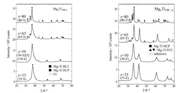
Figure I.7 XRD patterns of MgxTi100−x (x=35,50,65 and 80) alloys milled for 200h using
stainless steel milling balls and pots (in the left) and using zirconia milling balls and pots (in the right) (Cu Kα radiation) [25]. ... 25 Figure I.8 Phase diagram of Ni-Ti binary alloy ... 28
Figure I.9 Diffraction patterns of Ti1.01Ni0.99-xCux alloys a) at 473 K and b) at room temperature
(Cu Kα radiation) [45]... 30 Figure I.10 Mg-Ni binary phase diagram [66] ... 33
Figure I.11 Models of the unit cell of Mg2Ni [67]. ... 34
Figure I.12 XRD pattern evolution of Mg:Ni (1:1) with milling duration (Cu Kα radiation) [78]. ... 38
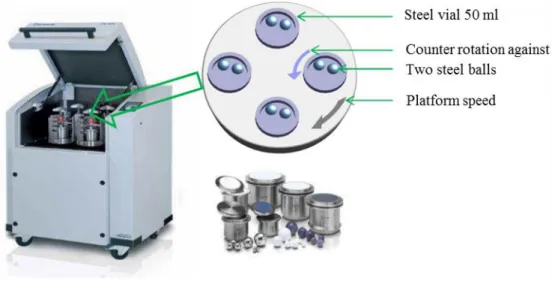
Figure II.1 Schematic depicting the ball motion inside the ball mill [2]. ... 54
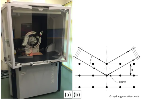
Figure II.3 Photography and X-ray diffraction mechanism of Bruker-AXS D8 FOCUS
Advanced Bragg-Brentano X-ray Powder Diffractometer. ... 58
Figure II.4 JSM-7800F field emission scanning electron microscope. ... 59
Figure II.5 Example of TEM diffraction image. ... 61
Figure II.6 TEM model JEOL JEM-2100. ... 62
Figure II.7 Equipped TEM sample preparation platform. ... 63
Figure II.8 Schematic diagram of a manometric sorption measurement system... 64
Figure II.9 PCTPro Sievert’s type apparatus. ... 65
Figure II.10 Simplified block diagram of a chronopotentiometric measurement device. ... 66
Figure II.11 Appearance of Muti-channel Battery test platform. ... 67
Figure III.1 The morphologies of starting materials: (a) Ti, (b) Mg and (c) Ni. ... 83
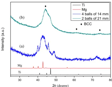
Figure III.2 XRD results of Ti50Mg50 alloys ball milled for 60 h by (a) 4 balls of 14 mm and (b) 2 balls of 21 mm. ... 85
Figure III.3 XRD results of Ti50Mg50 alloys ball milled in (a) 200 PPM for 100 h and (b) 400 RPM for 60 h... 86
Figure III.4 XRD results of Ti50Mg50 alloys ball milled for 60 h (a) with PCA and (b) without PCA. ... 87
Figure III.5 XRD results of Ti50Mg50 alloys ball milled for (a) 5 min, (b) 10 h, (c) 20 h, (d) 40 h and (e) 60 h. ... 88
Figure III.6 XRD patterns of (a) TiMgNi0.2, (b) TiMgNi0.4, (c) TiMgNi0.6, (d) TiMgNi0.8, (e) TiMgNi milled 40h... 89
Figure III.7 XRD patterns of TiMgNi0.2 milled for (a) 20 h, (b) 40 h and XRD pattern of TiMgNi0.1 milled 40h (c) ... 90
Figure III.8 XRD patterns of TiMgNi0.4 mixture after different milling time: (a) 20 h, (b) 40 h.
... 92
Figure III.9 XRD patterns of TiMgNi mixture after different milling time: (a) 20 h, (b) 40 h. ... 94
Figure III.10 SEM micrographs of (a) TiMgNi0.2, (b) TiMgNi0.4, (c) TiMgNi0.6, (d) TiMgNi0.8,
(e) TiMgNi milled 40h ... 95
Figure III.11 Discharge capacities as a function of charge/discharge cycles of TiMgNix alloys.
... 97
Figure III.12 XRD patterns of electrode, after 21 cycles of electrochemical studies (a) TiMgNi0.2, (b) TiMgNi0.4, (c) TiMgNi0.6, (d) TiMgNi0.8, (e) TiMgNi. ... 99
Figure III.13 Transmission electron microscopy image (a) for the as-milled TiMgNi alloy and its corresponding selected area electron diffraction (SAED) (b) and EDS map (c) ... 100
Figure III.14 Transmission electron microscopy image for the as-milled TiMgNi alloy and its corresponding selected area electron diffraction. ... 102
Figure III.15 Dark field image of as-milled TiMgNi alloy (a) and its corresponding selected area (SAED) images with points of measurements (b). ... 103
Figure III.16 HRTEM image of the nanocrystallites. ... 103
Figure III.17 Pressure-composition-isotherm (PCI) curves of TiMgNix alloys (x = 0.2, 0.4, 0.6,
0.8 and 1) measured at 598 K ... 104
Figure III.18 XRD patterns of (a) TiMgNi0.4, (b) TiMgNi0.6,(c) TiMgNi0.8 and (d) TiMgNi
alloys after dehydrogenation ... 105
Figure III.19 XRD patterns of TiMgNi after (a) mechanical alloying (b) activation (c) hydrogenation (b) dehydrogenation ... 106
Figure III.20 XRD patterns of (a) MgTi0.8Ni0.2, (b) MgTi0.6Ni0.4, (c) MgTi0.4Ni0.6 and (d)
Figure III.21 TEM micrograph of MgTi0.4Ni0.6 (a) and corresponding EDS mapping analysis
of (b) Mg, (c) Ti and (d) Ni. ... 111
Figure III.22 Discharge capacities as a function of charge/discharge cycles of MgTixNi1-x alloys.
... 112
Figure III.23 XRD patterns of (a) TiMg0.8Ni0.2, (b) TiMg0.6Ni0.4, (c) TiMg0.4Ni0.6 and (d)
TiMg0.2Ni0.8 milled for 40 h. ... 114
Figure III.24 XRD patterns of TiMg0.2Ni0.8 milled for (a) 10 h, (b) 20 h and (c) 40 h... 116
Figure III.25 Transmission electron microscopy image for the as-milled TiMg0.2Ni0.8 alloy (a)
and its corresponding selected area electron diffraction (b). ... 116
Figure III.26 Discharge capacities as a function of charge/discharge cycles of TiMgxNi1-x alloys.
... 117
Figure III.27 Illustration of discharge capacities as a function of ternary alloys in Ti-Mg-Ni system... 118
Figure III.28 XRD results of TiMgNi milled for (a) 10 h, (b) 20 h, MgTi0.4Ni0.6 milled for (c)
10 h, (d) 20 h and TiMg0.4Ni0.6 milled for (e) 10 h, (f) 20 h. ... 123
Figure III.29 Discharge capacities as a function of charge/discharge cycles of TiMgNi milled for (a) 10 h, (b) 20 h, MgTi0.4Ni0.6 milled for (c) 10 h, (d) 20 h and TiMg0.4Ni0.6 milled for
(e) 10 h, (f) 20 h. ... 124
Figure IV.1 XRD patterns of Ti-Ni and Ti-Ni-Cu alloys after 20 h of milling: (a) TiNi, (b) TiNi0.9Cu0.1, (c) TiNi0.8Cu0.2, (d) TiNi0.7Cu0.3. ... 139
Figure IV.2 SEM micrographs of annealed samples: (a) TiNi, (b) TiNi0.9Cu0.1, (c) TiNi0.8Cu0.2,
(d) TiNi0.7Cu0.3. ... 140
Figure IV.3 XRD patterns of annealed Ti-Ni and Ti-Ni-Cu alloys at 750 °C for 0.5 h: (a) TiNi, (b) TiNi0.9Cu0.1, (c) TiNi0.8Cu0.2, (d) TiNi0.7Cu0.3. ... 142
Figure IV.4 The total DOS of TiNi1-xCux alloys. The Fermi level is chosen as the origin of the
energy. ... 145
Figure IV.5 The structural illustration of TiNi1-xCuxH system. ... 147
Figure IV.6 The discharge capacities as a function of charge/discharge cycles of annealed Ti-Ni and Ti-Ti-Ni-Cu alloys. ... 149
List of tables
Table I.1 A subset of original and revised DOE targets for on-board hydrogen storage systems
for light-duty vehicles [9]. ... 11
Table I.2 Products of Ti-Mg alloys with different approaches ... 22
Table III.1 Discharge capacities and retaining rates of as-milled samples ... 98
Table III.2 Quantitative analysis on the element compositions of zone 1 in Figure III.12 (C) ... 101
Table III.3 Structural characteristic and discharge capacities of as-milled samples. ... 120
Table IV.1 Average particle size and chemical composition of annealed samples. ... 141
Table IV.2 Experimental and calculated lattice parameters of annealed samples. ... 143
Table IV.3 Calculation results of hydrogen adsorption energy of TiNi1-xCux alloys ... 147
INTRODUCTION
Hydrogen is a clean and renewable energy carrier, which can be used to store and transport energy. It is an ideal energy resource as a cold combustion fuel to produce electrical energy, e.g. in fuel cell due to its higher efficiency and zero pollution compare to diesel or gas engines. However, before the arrival of hydrogen-driven economy, some major technical challenges need to be conquered, one of which is finding an efficient and safe hydrogen storage medium with a small volume and low weight. A few currently available technologies permit to store directly hydrogen by modifying its physical state in gaseous or liquid form. But these methods have shortcomings such as: safety concerns, energy loss during operation, cost of recycling and charging infrastructures etc... In addition to these traditional stored form, solid-state hydrogen storage methods bring new possibilities for on-board utilization of hydrogen. A great deal of effort has been made on new hydrogen-storage systems, including metal, chemical or complex hydrides and carbon nanostructures. Metal hydrides are some metals and alloys which can reversibly absorb and desorb hydrogen under moderate temperature and pressure which gives them an important safety advantage over the gas and liquid storage methods. For the vehicle application, depending on the temperature of hydrogen absorption/desorption below or above 150 °C, the alloy hydrides can be classified in high and low temperature materials. The principal disadvantages of alloy hydrides, apart from the cost, are the low hydrogen content at low temperature (e.g. La-based alloys) and the difficulty of reducing desorption temperature and pressure of alloy hydrides having high hydrogen storage capacity and fast rate (e.g. Mg-based materials).
To solve the above mentioned problems, composite materials, partial substitution and modification of composition have been systematically studied for synthesizing novel catalyzed metal hydrides.
Additionally, another notable application area for hydrogen storage material is in Nickel-Metal Hydride batteries. The Ni–MH battery has been widely employed for high-current drawing devices, including mobile phones and laptops, due to its safety, environmental friendliness and overall charge–discharge performance. The metal hydrides used as the negative electrodes of Ni-MH batteries are the key components for battery performance, namely discharge capacity, high-rate capability, initial activation, cycling life, self-discharge rate. In order to compete with the Li-ion battery in emerging electric vehicle (EV) andhybrid electric vehicle (HEV) market, the energy density of the Ni–MH battery needs to be greatly increased. Replacing Li-ion batteries is preferable as these batteries require expensive special safety equipment that prevents over discharging the battery, whereas Ni/MH batteries do not require any special safety equipment. In recent years, a lot of high performance hydrogen storage alloys have been developed. Among them, magnesium based and titanium based alloys have attracted much attention due to their extremely high discharge capacity and low cost.
Theoretically, the hydrogen storage abilities of MgH2 and TiH2 are 7.6 wt.% and
4.0 wt.% respectively. However, due to the irreversible hydrogen absorption reaction of TiH2 at room temperature and the low decomposition-formation kinetics of MgH2,
neither of them can be practically applied. In order to improve their hydrogen storage properties, transition metal elements have been introduced as electrocatalysts into the
system. For example, amorphous MgNi was measured to process a high electrochemical capacity reaching 500 mAh/g, but with a bad cycling performance. The crystalline Mg2Ni can reversibly absorb and desorb hydrogen at high temperature.
However, the poor kinetics and bad anti-oxidation of Mg2Ni cannot be ignored. TiNi
phase was found to possess a capacity of 230 mAh/g and good corrosion resistance in alkaline solution. Unfortunately, the poor absorption/desorption kinetics and complex activation procedure are obstacles for the practical application of TiNi alloys as hydrogen storage material.
These two binary alloys are far from being operational in practical applications due to their mediocre cycling stability and relatively low discharge capacity. Fulfilling all the requirements for optimum performance of hydrogen-based batteries remains thus a real challenge. To overcome this problem, composite hydride materials have been introduced as electrode materials in an attempt to improve the balance of discharge capacity and cycling performances. Alloys pertaining to the Ti-Mg-Ni ternary system are of interest as potential metal hydride since they consist of two hydride forming metals of Ti and Mg. The hydrogen storage properties of these alloys could be upgraded with Ni additions thanks to the high catalytic activity of the latter. A lot of researchers have made efforts to optimize the composition for exploring the balance of discharge capacity and cycling performance. There is therefore a vivid interest for the development of such ternary Ti-Mg-Ni systems in view of hydrogen storage applications.
The objective of the present study is to explore the hydrogen storage properties of Ti-Mg-Ni ternary alloys system and investigate the synergistic effect of different phases on the enhancement of electrochemical performance. Furthermore, this thesis studied the Ti-Ni system with Cu substitution. Meanwhile, the structure of substituted alloys was simulated with first principles calculations in order to have qualitative insight into the variation of their properties. High energy ball milling (HEBM) and subsequent heat treatments have emerged as the technology of choice for their preparation.
In Chapter I, the metal hydride as a hydrogen storage material and the working mechanism of Ni-MH system as a new form of energy storage form is briefly presented. Afterwards, an introduction on the main varieties of metal hydrides namely Ti-Mg system, Ti-Ni system, Mg-Ni system and Ti-Mg-Ni ternary system are given with an emphasis on recent research on their use as the negative electrode material for Ni-MH batteries.
In Chapter II, the high energy ball milling (HEBM) preparation method as well as its applications in the hydrogen storage material field have been presented. The main instruments for structural characterization and hydrogenation properties measurements used in this study are introduced. This entails of X-Ray Diffraction, Scanning Electron Microscopy, Transmission Electron Microscopy, PCI test and electrochemical properties under galvanostatic conditions. At last, the principle of Density functional theory (DFT) calculation is explained with some words on the application CASTEP (Cambridge Serial Total Energy Package) that we used subsequently to study the Cu substituted Ti-Ni alloys.
In Chapter III, a series of Ti-Mg-Ni alloys have been synthesized by mechanical alloying using a planetary high-energy ball mill. The effect of Ni addition in TiMg, partial substitution of Ni for Ti in TiMg and partial substitution of Ni for Mg in TiMg have been studied through the compared analysis of TiMgNix, MgTi1-xNix and TiMg 1-xNix. The effect of the variation of composition and milling time on the microstructure
and hydrogenation properties of Ti-Mg-Ni alloys are investigated. Additionally, an approach used to improve the electrochemical properties of Ti-Mg-Ni alloys is developed.
In Chapter IV, Cu substituted TiNi alloys have been investigated as hydrogen storage material for Ni-MH batteries by experiments and first principles calculations. The phase transformations and electrochemical properties of TiNiCu alloys are characterized. The influence of Cu substitution for Ni on their electronic structure and hydrogen adsorption energies are investigated by first principles calculations.
In chapter V, the main points of this study which concern the products preference and hydrogenation properties of Ti-Mg-Ni alloys as well as the experimental and computational results of the influence of Cu substitution on the structural and electrochemical properties of TiNi alloys have been summarized. Prospective views on current research as how it can be continued for further investigation in the search of ideal materials for the negative electrode for Ni-MH batteries have been given.
In appendix I, the publications and attended conferences during PhD studies are listed.
CHAPTER I
Overview of metal hydrides and their
applications in Ni-MH batteries
This chapter gives a brief review on hydrogen storage materials and their application as the main materials in the negative electrode of nickel/metal hydride (Ni-MH) secondary batteries. The Ti-Mg-Ni ternary alloys, as the main research object in present study, are introduced from the aspects of Ti-Mg system, Mg-Ni system, Ti-Ni system and Ti-Mg-Ni system. The common ways for manufacturing these hydrogen storage materials are also included.
I.1 Hydrogen storage methods
As energy crisis and environmental pollution are becoming more and more serious, it is very urgent to seek alternative clean energy resources to replace the traditional fossil fuel. Hydrogen is widely regarded as one of the best solutions due to the following reasons [1, 2]: (1) Readily Available: Hydrogen is the most abundant element on earth and can never run out theoretically. (2) No Harmful Emissions: Using hydrogen as a fuel is clean and renewable. (3) Environment Friendly: Hydrogen is also non-toxic, which makes it a rarity among fuel sources. (4) Fuel Efficient: Compared to traditional fossil fuel, hydrogen is much more fuel efficient as it can produce more energy per pound of fuel. Especially, since the development of the proton exchange membrane (PEM) fuel cell, which takes in hydrogen gas as fuel and produces only water, hydrogen appears as the most promising energy carrier and has attracted increasing research attentions.
However, a key step for the development of hydrogen technology in application including stationary power and portable power requires overcoming the technical
challenge of storage and transport of hydrogen. Hydrogen is very hard to move around compared to traditional energy carriers. Many approaches have been implemented for solving this issue which can be simply classified as physical storage and chemical storage [3]. In this chapter, we will limit our discussion to the hydrogen storage in gaseous form, liquid form and metal hydride, each of these options possesses attractive attributes for hydrogen storage.
I.1.1 Hydrogen storage in gaseous form
Physical storage is the most mature hydrogen storage technology. Hydrogen can be stored physically as either a gas or a liquid. The storage of hydrogen involves a balance and compromise between two different aspects of the storage system; the volumetric and gravimetric capacities. The application scenario of hydrogen results in its preferable storage technology.
Hydrogen has been stored as compressed gas in storage tanks since the beginning of the 20th century. The tanks can either be made with steel, aluminum or copper alloys
that may be encased in fiberglass. The steel tanks are most often used for stationary applications where weight is not a hindrance as the steel tanks tend to be bulky and heavy. High pressure tanks also appear in some test automobiles but safety and space remain significant concerns. The major drawback of gaseous storage for transportation applications is the small amount of hydrogen that may be stored in a reasonable volume. Even though 10,000 psi (~70 MPa) hydrogen tanks [4] have been successfully employed commercially , the energy content of such hydrogen tanks is significantly
less than that for the same volume of gasoline, 4.4 MJ/L (10,000 psi) for hydrogen compared with 31.6 MJ/L for gasoline [5]. Another consideration in the storage of compressed hydrogen requiring special caution is the problem of hydrogen embrittlement, because many of the system parts exposed to hydrogen are metallic. The hydrogen embrittlement of metallic hydrogen tanks occurs under high pressure and high temperature conditions and may result in the cracking of tanks. Thus, all these factors raise a big challenge for the development of tank materials, which should be not only reliable enough but also light of the same time.
I.1.2 Hydrogen storage in liquid form
Hydrogen in liquid form has a considerably higher energy density than in its gaseous form, making it an attractive storage medium. Hydrogen can be stored as a liquid at 21.2 K (-251.95°C) at ambient pressure in cryogenic tanks because the boiling point of hydrogen at one atmosphere pressure is −252.8°C. It is predicted that the energy content of liquid hydrogen is 8.4 MJ/L [6] compared with 4.4 MJ/L for compressed gas (at 10,000 psi). A major drawback of liquid storage is the large quantity of energy required for liquefaction. The cooling and compressing process requires energy, resulting in a net loss of about 30% of the energy stored in the liquid hydrogen. High-pressure cryogenic tanks are also being explored to alleviate the requirement for very low temperature storage [7]. The main task is to reduce the cost of liquefaction and make it more energy efficient. Besides, the problem of hydrogen boil-off is another unavoidable phenomenon when hydrogen is stored as a liquid form. The boil-off rate
of hydrogen from a liquid hydrogen storage vessel is associated with the size, shape and thermal insulation of the vessel. The best shape for vessel is a sphere, however, large-sized spherical containers are expensive due to the manufacturing difficulty. For these reasons, the practical application of liquid hydrogen storage system is quite limited which are mainly in the fields that, the cost of hydrogen is not an important issue and the hydrogen is consumed in a relatively short time, e.g. space applications and military aircrafts [8].
Figure I.1 Volumetric density of compressed hydrogen gas as a function of gas pressure, including the ideal gas and liquid hydrogen. The ratio of the wall thickness to the outer diameter of the pressure cylinder is shown on the right side for steel with a tensile strength of 460 MPA. A schematic drawing of the pressure cylinder is shown
as an inset [5].
To illustrate the relationship between storage efficiency and pressure, Figure I. 1. shows the volumetric density of hydrogen inside the cylinder and the ratio of the wall thickness to the outer diameter of the pressure cylinder for stainless steel with a tensile strength of 460 MPa [5]. It is shown that the volumetric density of liquid hydrogen is
steady and always higher than that of compressed hydrogen gas. The volumetric density of compressed hydrogen gas increases with pressure and reaches a maximum above 1000 bar, depending on the tensile strength of the material. However, the gravimetric density decreases with increasing pressure and the maximum gravimetric density is found for zero overpressure. Therefore, the increase in volumetric storage density is sacrificed with the reduction of the gravimetric density in pressurized gas systems [8].
Table I.1 A subset of original and revised DOE targets for on-board hydrogen storage systems for light-duty vehicles [9].
Storage system parameter Original 2010 target Revised 2010 target 2017 target Ultimate target
Gravimetric capacity kgH2 /kg 6% 4.5% 5.5% 5.5%
Volumetric capacity g H2/L 45 28 40 70
Operational cycle life 1000 1000 1500 1500
Filling time (min, for 5 kg) 3 4.2 3.3 2.5
Fuel purity 99.99% 99.97% 99.97% 99.97%
As storing hydrogen is a key aspect of a hydrogen energy infrastructure, the US Department of Energy (DOE) released targets for hydrogen storage systems in 2003. Whereas, the targets were revised in 2009. The DOE targets consider volumetric and gravimetric capacities, refilling time, costs, cycle life and loss of usable hydrogen. The original and revised DOE targets are shown in Table I. 1. It is indicated that the standard of revised 2010 targets are lowered somewhat in comparison to the original 2010 targets with regard to system gravimetric capacity, system volumetric capacity, and refilling time, which means the hydrogen storage for onboard application is not that easy to
accomplish. Especially, the volumetric and gravimetric capacities are considered along with cost and efficiency [10]. DOE analyses are most readily available for physical methods of hydrogen storage because they are the most traditional storage methods and so were the first to be investigated. Unfortunately, no physical hydrogen storage technology currently meets DOE standards [11], because hydrogen is diffuse and buoyant and with extremely low density. Although it has been stored in the gaseous form for centuries and as a liquid since the 1940’s, traditional mechanical means of hydrogen storage (compression and liquefaction) are very energetically and financially expensive. Therefore, research is constantly underway to improve these storage techniques and develop new storage mechanisms. Many alternative storage methods are being extensively investigated, in which, metal hydride is one of the most potential candidates for solving this technical issue.
I.1.3 Hydrogen storage in metal hydride
Although with the compressed and liquid storage options, hydrogen is accessible for use, these storage methods still cannot meet either the options of DOE targets or practical demands of on-board hydrogen storage system for mobile applications. Hydrogen storage requires a great technological discovery, that is, chemical storage, where hydrogen is stored in hydrides. Through a chemical reaction, solid metal hydrogen compounds are formed, under hydrogen pressure, and heat is released. For example, 4 kg of hydrogen will be needed to enabled a vehicle with a fuel cell engine to drive a distance of 400 km. Figure I. 2. gives a visual comparison of volumetric scale for storing 4 kg of hydrogen in different ways. It can be found that, the volumetric
densities of chemical hydrides (i.e., Mg2NiH4 and LaNi5H6) are much higher than that
of compressed hydrogen and liquid hydrogen. Chemical hydrides, therefore, are mainly considered as the most potential technology for storing hydrogen.
Figure I.2 Volume of 4 kg of hydrogen compacted in different ways, with size relative to the size of a car [6].
Metal hydrides are kind of solid metal-hydrogen compounds which are generated by the reaction of metals, intermetallic compounds and alloys with hydrogen. They can be grouped into three basic types according to the nature of the metal-hydrogen bonds: ionic, volatile covalent and metallic hydrides [8]. Since the first hydrogen absorption phenomenon was found for palladium, various metallic compounds have been proposed as hydrogen storage materials. Actually, almost all of the elements can form binary hydrides with hydrogen, except the inert gas elements. But due to the problems of capability and reversibility, neither of them can be practically used. The intermetallic hydrides, by contrast, are more attractive because they can adsorb and desorb hydrogen under moderate conditions.
As seen in figure I. 3, which illustrate the schematic model of a metal structure with H atoms in the interstices, charging process can be done using molecular hydrogen gas or hydrogen atoms from an electrolyte [6]. The hydrogen molecule is first absorbed on the surface and then dissociated as strongly bound, individual hydrogen atoms. The hydrogen atoms can diffuse into the metal and form a solid solution of hydrogen atoms dissolved in the metal lattice, which is usually referred to as the α-phase. When the hydrogen pressure increases and the concentration exceeds a certain critical value, a higher concentration hydride phase (β-phase) starts to form. While the pure β-phase is obtained, α-phase disappears in the mean time, hydrogen enters as the solid solution of β-phase. On the contrary, when the hydrogen needs to be used, it is released from the hydride under certain temperature and pressure conditions following the reversible process. This process can be repeated many times without loss of storage capacity.
Figure I.3 Schematic model of a metal structure with H atoms in the interstices between the metal atoms, and H2 molecules at the surface [6].
Intermetallic hydrides contain at least two metals in addition to hydrogen. The general formula of two-metal hydrides are AmBnHx, where metal A has a strong
affinity for hydrogen and forms a stable binary hydride while metal B does not interact with hydrogen, such as LaNi5 (CaCu5 structure type), TiNi (CsCl structure
type) and Mg2Ni (AlB2 structure type) etc. The hydrides will be formed when the
intermetallic expose to hydrogen and follow the reaction:
M +x2H2 ↔ MHx+ Q EQN I.1.
Where M represents the metal and Q is the heat of reaction of hydride formation. The thermodynamic aspects of the hydride formation from gaseous hydrogen can also be described by the means of pressure-composition isotherms (as shown in Figure I. 4). Metal and hydrogen usually form two different kinds of hydrides, α-phase at which only some hydrogen is absorbed and β-phase at which hydride is fully formed. While the two phases coexist, the isotherms show a flat plateau (in the middle of the curve). The length of this plateau reveals the amount of stored hydrogen. Accompanying the increase of temperature, the pressure of its plateau increases linearly until the critical point, Tc, above which the phase transition of α-phase to β-phase takes place continuously [12].
Figure I.4 Schematic PCT diagram at different temperature (T1<T2<T3<T4<Tc) (left side), and the Van’t Hoff plot (right side) [13].
The Van’t Hoff plot is an appropriate way to estimate the pressure-temperature stability of hydrides. In Figure I. 4, a Van’t Hoff plot is also presented on the right side for reporting the values of ln(P) as a function of 1/T, through the EQN I.2.
ln (𝑃𝑃 0) = ∆𝐻 𝑅𝑇− ∆𝑆 𝑅 EQN I.2.
Where P is the equilibrium pressure and R is the gas constant (8.3145 J mol−1 K−1). ΔH and ΔS are respectively the enthalpy and entropy of the formation of the hydride (β-phase). The slope of the line is equal to the dehydrogenation enthalpy divided by the gas constant (ΔH/R), and the intercept is equal to the entropy of formation divided by the gas constant (ΔS/R).
I.2 Application of metal hydride in Ni-MH battery
I.2.1 General introduction of Ni-MH battery
Nickel/metal hydride (Ni/MH) rechargeable batteries are one of the important power sources for various consumer types of mobile applications, stationary energy storage, and, most distinctively, transportation usages. Because of its durability, abuse tolerance, compact size, and environmental friendliness, Ni/MH battery applications have steadily expanded from the traditional consumer market to include propulsion and telecommunications [14].
Although Ni/MH batteries have an excellent track record for high abuse-tolerance and endurable service life, these batteries suffer from a relatively low gravitational energy density when comparing to Li-ion batteries [15]. In the meantime, Ni/MH battery technology also earned itself a place in the primary alkaline battery market because of its voltage compatibility and low self-discharge, as well as the NiCd power tool market for its non-toxicity [16]. The success of Ni/MH in powering hybrid electric vehicles (HEV) developed by a handful of automobile manufacturers stems from its wide temperature range, abuse tolerance, superb cycle stability, high charge and discharge rate capabilities, and environmental friendliness [15].
I.2.2 Structure of Ni-MH battery
A Ni-MH battery mainly consists of the following parts: positive electrode, negative electrode, separator, electrolyte, case, and safety valve. A 30% KOH solution
is widely used as the electrolyte for Ni/MH batteries due to the balance of conductivity and freezing point temperature [17]. The basic electrochemistry reactions for the positive electrode and negative electrode are:
(Positive) Ni(OH)2 + OH¯ = NiOOH + H2O + e¯ (1)
(Negative) M + H2O + e¯ = MH + OH¯ (2)
And therefore the overall reaction is represented as:
(Overall) Ni(OH)2 + M = NiOOH + MH (3)
Where M is the hydrogen storage metal/alloy and MH is the hydride of metal M. The key to the whole reaction is in the negative electrode material where metal hydride is formed, and is also where all the research in the field has focused on. For better understanding of the charging and discharging process, the reversible reaction (2) can be decomposed into the following steps:
M + H2O + e¯ ↔ MHads + OH¯ (initial hydrogen adsorption) (4)
MHads ↔ MHabs (hydrogen diffusion) (5)
Habs ↔ MH hydride (metal hydride formation) (6)
2MHads ↔ M + H2 (hydrogen evolution) (7)
Where Hads, Habs represent adsorbed hydrogen on the alloy surface, absorbed hydrogen
in solid solution. The steps of hydrogen adsorption/desorption, hydrogen diffusion, and formation/decomposition of metal hydride can be illustrated by the reaction Eq.(4) - (6). During charge, Hydrogen is firstly produced by Eq. (4), known as Volmer reaction. A negative voltage (with respect to the counter electrode) is applied to the metal/metal hydride electrode current collector, and electrons enter the metal through the current collector to neutralize the protons from the splitting of water that occurs at the metal/electrolyte interface (Figure I. 5(a)).
Figure I.5 Schematics showing the electrochemical reactions between water and metal hydride during charge (a) and discharge (b) [18].
During discharge, the produced hydrogen can either be absorbed further into the alloy as solid solution, or start the hydrogen evolution reactions, which are the Tafel reaction (Eq. (7)) or even Heyrovsky reaction (Eq. (8)). Protons in the MH leave the surface and recombine with OH¯ in the alkaline electrolyte to form H2O, and charge
neutrality pushes the electrons out of the MH through the current collector, performing electrical work in the attached circuitry (Figure I. 5(b)).
I.3 Ti-Mg-Ni system
I.3.1 Hydrogenation properties of Ti-Mg system
In recent years, a lot of high performance hydrogen storage alloys have been developed. Among them, magnesium based and titanium based alloys have attracted much attention due to their extremely high discharge capacity and low cost. Theoretically, the hydrogen storage abilities of MgH2 and TiH2 are 7.6 wt. % and 4.0
wt. % respectively. However, due to the irreversible hydrogen absorption reaction of TiH2 at room temperature and the low decomposition-formation kinetics of MgH2,
neither of them can be practically applied. In order to optimize the hydrogen storage property of the light weighted metal hydrides, many efforts have been done on the Ti-Mg system. It has been identified as potential materials for hydrogen storage because of their safety, small volume and low weight.
It is known that, titanium has a melting point (1943 K) that greatly exceeds the boiling point of magnesium (1363 K). In addition, the equilibrium solid solubility of each metal in the other is very weak and no intermetallic compounds can be found in Ti-Mg binary phase diagram (as shown in Figure I. 6). Therefore, alloying of Mg and Ti by rapid solidification or regular melting method is extremely difficult. Some preparation methods like, physical vapor deposition (PVD), electron-beam and magnetron co-sputter deposition techniques have been employed for manufacturing Ti-Mg alloys [18], but it remains the problem that these techniques can not be scaled-up to industrial level. Instead, Mechanical alloying (MA) is a good candidate which is suitable for fabricating bulk materials as required for Ni-MH battery and fuel cell applications and has been proved to be an excellent technique for extending terminal solid solubility [20].
Many experimental studies have been carried out for investigating the phase transformation of Ti-Mg alloys by means of mechanical alloying. Liang et al. [21] reported the extended dissolution of Ti in Mg up to a maximum of 12.5 at.% upon milling of Mg80Ti20 alloys. Rousselot et al. [22] have synthesized Mg100−xTix (40≤x≤
80) alloys by means of ball milling which are made of two phases, namely, a Ti-rich hcp phase and a bcc phase. Kalisvaart and Notten [23] have synthesized MgxTi100−x (65
≤x≤85) alloys by means of ball milling which consisted of two face centered cubic (FCC) phases. Some of comparable results collected from the literatures are summarized in Table I.2.
Table I.2 Products of Ti-Mg alloys with different approaches
Starting materials Products Lattice Å Comments
Mg-20at.%Ti 12.5% Ti in Mg lattice, Mg42Ti58H177,FCC c/a ratio 1.612
The supersaturated Mg-Ti decomposes upon thermal annealing above 200◦C MgH2 and TiH2
ratio 7:1
Mixture Mg MgH2 and TiH
Release 5.91 wt.%, faster than that of MgH2 under similar conditions MgH2(Mg)+
TiH2(Ti), 1:1
FCC 4.46
4.48
Max (first) discharge 300, 443 and 454 mAh/g. Bad cyclicity. Ti–10Mg and Ti–
20Mg
FCC 32Hour, Each milling run used 100
g of powder mixture
Mg50Ti50
BCC (Mg42Ti58H177 --FCC)
4.49 4.7 mass%, hydrogenated at 423 K for 122 h consisted of the FCC
hydride phase and MgH2 MgxTi100−x
(x=35, 50)
FCC 4.30
4.31
milling using zirconia milling balls and pots,200h
MgxTi100−x (x=65, 80)
FCC and HCP milling using zirconia milling balls
and pots MgxTi100−x
(x=35, 50)
BCC 3.38
3.42
using stainless steel milling balls and pots
MgxTi100−x (x=80)
HCP 3.17 using stainless steel milling balls
and pots Mg50Ti50
– 3.3 at.% Pd
BCC+HCP 3.42 20h. the electrode discharge
capacity increases with the Pd content. Maximum=3.3% Mg0.25Ti0.75
Mg0.25Ti0.75H1.62 FCC phase hydride
hydride contained numbers of stacking faults introduced MgxTi1-x
(x=0.15,0.35)
FCC phase + TiH2 / MgH2 respectively
It is shown that the crystal structure of as-milled Ti-Mg alloys can be very different depending on the milling parameters and the atom ratio of Mg and Ti. The milling parameters can be further subdivided into milling speed, milling duration, grinding media and addition of PCA. Taking Ti50Mg50 as an example, both of Mg and Ti have a
hexagonal close packed (HCP) structure, but the phase structures of milling products via different synthetic approaches are BCC and FCC, respectively [24, 25]. These authors first synthesized a BCC Mg50Ti50 alloy by ball milling a mixture of 50Mg +
50Ti in a Fritsch P5 planetary ball mill with still balls for 200 h at a rotation speed of 200 rpm. While using zirconia milling balls and pots for ball milling using the same starting material in the same milling conditions, a FCC Mg50Ti50 alloy was obtained.
These variations of phase structures of as-milled samples with the same composition are mainly explained by the plastic deformation process of raw materials during ball milling. The density of stacking faults introduced by milling in the BCC phase is higher than that in the FCC phase because the dynamic energy given by stainless steel balls during milling was higher than that by zirconia ones. The main plastic deformation modes of Ti and Mg are twinning deformation and plane slips, respectively [26]. The different plastic deformation modes caused by various milling conditions further affect the phase structures of milling products. In another investigation of Mg50Ti50 alloys
prepared by high-energy mill, twinning deformation was also observed in Ti-rich crystallites at intermediate milling time [103]. They attributed the twinning to the deformation of Ti particles. But they also pointed out that in the Mg–Ti system it might also indicate a strain-induced martensitic transformation of the metastable ω-FCC into BCC. The crystallite boundaries acted as preferential sites for the heterogeneous nucleation of the twins and for the formation of solid solution by release of the lattice strain energy.
By controlling milling conditions and atom ratio of Mg and Ti, Asano et al. [25] have also shown that BCC, FCC or HCP phases could be obtained in the Mg–Ti system by ball milling (as shown in Figure I. 7). The HCP phase was formed by solution of Ti into Mg and the BCC phase by solution of Mg into Ti. While, the FCC phase was
stabilized by introduction of stacking faults in Mg and Ti which have a HCP structure. While MgH2 is used instead of Mg as the starting material then, after ball milling a
50MgH2 + 50Ti mixture, the resulting compound is FCC Mg33Ti50H94 and trace amount
of MgH2 [27]. Meanwhile, the importance of mechanical effect during milling has also
been discussed [28]. It shows that during ball milling of Mg and Ti powders in molar ratio of 1:1, plate-like particles first stick on the surface of the milling pot and balls. After these plate-like particles fall off from the surface of the milling pot and balls, spherical particles, in which concentric layers of Mg and Ti are disposed, are formed. These particles have an average diameter of 1 mm. These spherical particles are then crushed into spherical particles with a diameter of around 10 µm by introduction of cracks along the boundaries between Mg and Ti layers. Finally, the Mg50Ti50 BCC phase
with a lattice parameter of 0.342(1) nm and a grain size of 3 nm is formed. During milling, Ti acts as an abrasive for Mg which has stuck on the surface of the milling pot and balls.
Figure I.7 XRD patterns of MgxTi100−x (x=35,50,65 and 80) alloys milled for 200h
using stainless steel milling balls and pots (left) and using zirconia milling balls and pots (right) (Cu Kα radiation) [25].
Machio et al.[29] investigated the relationship between the milling time and the thermal stability of Ti-Mg powders which suggested that milling time needs to be optimized for any alloy system since it affects green densities and further processing of the milled powder. Meanwhile, the particle size of starting materials also have significant influence on the milling efficiency. Starting with fine titanium and magnesium particles in ball milling could result in a higher milling yield [24]. Increasing the amount of process-control agent (PCA), could also improve this phenomenon, however, contamination of the milled powder may be a shortcoming to this solution [30]. Kalisvaart et al. [23] reported that the lattice parameter of Ti-Mg FCC phase depended on the composition, i.e., the smaller FCC phase was Ti-rich and the larger one was Mg-rich. It is notable that, all these variations of the lattice parameter and the crystal structure of the milling products could further affect their hydrogen storage property significantly which should be brought to the attention.
Mg-Ti alloys are promising candidates as negative electrode materials for Ni-MH batteries, due to their high hydrogen solubility. Based on the fact that the hydrogen atoms occupy the interstitial sites of crystal lattice in metal hydrides. A BCC structure has more interstitial sites than FCC and HCP structures. A body-centered cubic structure is a coarse packing structure and has more interstitial space than face-centered cubic and hexagonal close-packed structures [31]. Thus, BCC alloys are more attractive candidates to be explored as possible interstitial hydrogen storage materials. The best electrochemical performances, reported by Vermeulen et al. [32], for Ti-Mg based alloys were prepared by mean of electron beam deposition. Discharge capacities were from 750 mAh g−1 in Mg50Ti50 to 1750 mAh g−1 in Mg80Ti20. However, unlike the
Ti-Mg thin films, when prepared by mechanical alloying, Ti-Mg-Ti materials must be activated for electrochemical application by adding a few at.% of palladium [33]. Without adding Pd as catalyst, the hydrogen discharge capacity of as-milled Mg–Ti materials is close to zero. Rousselot et al. [33] reported a maximum discharge capacity of as-milled Mg50Ti50 alloy with 10 at.% Pd is 400 mAh g−1 after three charge/discharge
cycles. The structure of the alloy evolves from a HCP to a FCC structure upon cycling, and does not revert back to its original structure upon dehydrogenation.
A possible explanation for the function of Pd is that the dissolution of Pd changes the electronic structure of Ti-Mg alloy [34, 35]. The addition of Pd decreases the energy of the hydrogen-sites in the Mg-Ti alloys and has a beneficial effect on their electrochemical hydrogen discharge. Nevertheless, up to now, there is no alternative solution for replacing Pd as the electrochemical catalyst for as-milled Ti-Mg alloy
which has become the major disadvantage for its practical application considering the extremely high cost of Pd.
I.3.2 Hydrogenation properties of Ti-Ni system
Ti-Ni based alloys are quite attractive functional materials not only as practical shape memory alloys with high strength and ductility but also as those exhibiting unique physical properties and hydrogen storage performance. The memory behavior of TiNi is due to a reversible structural martensitic transformation (MT) from a high temperature phase with cubic structure and a low temperature phase with monoclinic structure [36]. Besides, there are many phase transformations in Ti-Ni based system, which include not only martensitic transformations, but also diffusional transformations. Let us note that, the phase diagram of NiTi has been controversial for nearly three decades before some consensus was established. The most reliable Ti-Ni phase diagram, according to the discussion of Otsuka and Ren [37], is shown in Figure I. 8. It can be found that, the stable phase structure exist in Ti-Ni phase diagram are TiNi, Ti2Ni and
TiNi3. For hydrogen storage, it is known that both TiNi and Ti2Ni in the Ti–Ni system
absorb hydrogen at room temperature. The electrochemical properties such as the discharge capacity, and the discharge kinetics of Ti–Ni alloys were studied based on these two compositions by synthesizing the alloys with raw materials of Ti and Ni with high purity.
Figure I.8 Phase diagram of Ni-Ti binary alloy [37].
I.3.2.1 TiNi in Ni-MH system
TiNi phase that has a CsCl type structure (space group pm3m-221), with a lattice constant of 3.15 nm at room temperature, which is also referred to as the high temperature phase or austenitic phase. The other type of TiNi is the martensite phase with a monoclinic B19' structure (space group P21/m) [38]. The first investigation of
TiNi as a reversible negative electrode for Ni–MH batteries was carried out by Justi et al. [39] in 1970. Afterwards, TiNi hydride received extensive research, thanks to its rather low specific weight, good oxidation resistance and notable discharge capacity: 240 mAh/g [40]. Besides, TiNi alloy is also the first alloy studied as a hydrogen storage material, which can absorb hydrogen as much as 1.4 H/f.u. (formula unit) under room temperature and pressure [41].
Lots of attempts have been made in order to improve the hydrogen storage properties of TiNi alloy through substituting element or refining the microstructure.
Various alloying elements have been used to improve the electrochemical capacity and cycle life of TiNi-based ternary alloys by the means of ball milling, e.g. Mg [42], Mn [43], Zr [43, 44], Cu [45], Fe [46] and B [47]. Szajek et al. [42] reported that the respective replacement of Ni in TiNi by Mg, Mn or Zr improved not only the discharge capacity but also the cycle life of these electrodes. They gave an explanation using band structure calculations, which showed that the introduced impurities cause decrease of the width of the valence bands.Emami et al. [48, 49] investigated the influence of Pd by partially replacing Ni [163,164]. It is indicated that the unit cell of TiNi is enlarged by the doped Pd, the electrochemical capacity is reduced since the Pd-substitution increases the stability of TiNi intermetallic alloy and decreases the stability of their hydrides according to the electronic calculations. In addition, some other studies on substituting Ni in TiNi with various modifiers revealed that Fe, Co, and Cr increase the electrochemical capacity up to 400 mAh g−1 with good activation performance [50]. The partial substitution of B for Ti and Ni realized by ball milling showed a formation of solid solutions of B in TiNi after milling, and subsequent annealing yields TiNi and TiNi3 phases, whose discharge capacity was found lower than the initial TiNi alloy [47].
Other preparing methods have also been employed for manufacturing TiNi based alloys and shown interesting results. Cuevas et al. [51] have reported a series of Ti 50-xZrxNi50 (x = 0, 6, 12, 18 and 24 at. %) alloys with austenite and martensite structure by
means of induction melting and melting-spinning, respectively. They also pointed that the type of parental crystal structure has a big influence on their hydrogenation properties. As for austenitic type (CsCl-type structure), the hydride preserves its metal
sublattice and forms Ti0.64Zr0.36NiH1.6 (PH2 = 1 MPa and T = 373 K), whereas the
monoclinic TiNi-type structure of martensitic Ti0.64Zr0.36Ni is hydrogenated into two
coexisting hydrides, Ti0.64Zr0.36NiH and Ti0.64Zr0.36NiH2.2 [52]. Martensitic
transformation in TiNi-alloys is promoted by Zr addition, hence can be used to tailor the final product of alloying Ti-Ni-Zr. Martensitic type structure can increase the hydrogenation percentage of TiNi significantly with an obvious PCI plateau, while the austenitic type shows no plateau on the PCI curve. Another study from Emami et al. [45] revealed the differences of hydrogen storage performance between austenitic and martensitic phase by substituting Cu in TiNi alloys. Pseudo-binary TiNi1-xCux (x ≤ 0.5)
compounds have been synthesized by induction melting. The XRD results in Figure I.9 show, that the products consist of B2 structure above 350 K and either of B19' (x < 0.1) or B19 (0.2 ≤ x ≤ 0.5) at room temperature. The electrochemical discharge capacity increases with Cu content from 150 mAh g-1 for TiNi up to 300 mAh g-1 for TiNi
0.8Cu0.2
and then decreases again for larger Cu amounts.
Figure I.9 Diffraction patterns of Ti1.01Ni0.99-xCux alloys a) at 473 K and b) at room
I.3.2.2 Ti2Ni in Ni-MH system
Another binary hydride with an fcc structure which is able to store considerable amount of hydrogen in Ti-Ni system is Ti2Ni. The first study of Ti2Ni as hydrogen
storage material was done in 1972, from which, Ti2Ni hydride was announced to have
a capacity as high as 500 mAh/g in a gaseous hydrogen absorption reaction [53]. Later studies were proposed by Luan et al. [54] using arc melting. They obtained only 160 mAh/g with poor cycling stability. The severe capacity loss during cycling limited the application of Ti2Ni alloy, which was attributed to the formation and accumulation of
irreversible Ti2NiH0.5 phase for hydrogen absorption/desorption, based on the results of
X-ray diffraction and charge and discharge testing [55]. Zhao et al. [56] conducted investigations on the performance of amorphous Ti2Ni alloy. They found that
amorphous phase of Ti2Ni contribute to the promotion of the cycling performance. The
alloy was synthesized by solid-state sintering and then ball milling to obtain an amorphous phase, which had a rather stable discharge capacity that ranges from 100 mAh/g to 125 mAh/g. In comparison, the discharge capacity of non-milled Ti2Ni
(alloyed by solid-state sintering) reached 280 mAh/g in the first cycle, but dropped to less than 100 mAh/g after 50 cycles. Hosni et al. [57] investigated the influence of the working temperature on the electrochemical performance of Ti2Ni alloys. They
indicated that, the electrochemical discharge capacities and cycling suitability of Ti2Ni
alloys are increased and decreased respectively with the increase of temperature. In the aspect of Ti2Ni as hydrogen storage material, the highest hydrogen storage capacity
Ti2Ni was prepared by mechanical alloying and annealing with addition of 5 wt.% of
Pd.
Elemental substitution of Ti2Ni alloy showed slight improvements in the
electrochemical hydrogenation properties. Substitution of Al and B for Ni was carried out by arc melting, but the improvement was not satisfactory [59]. Li et al. [60] studied the effect of Zr substitution on the electrochemical properties of Ti2Ni alloys, in which,
the discharge capacity drops drastically with Zr substitution, but with increase of Zr content (from x = 0.1 to x = 0.2), the discharge capacity increases generally, which credits to larger unit-cell-volume caused by Zr substitution. Hiroyuki et al. [61] experimented on the hydrogenation process of the ternary compound Ti4Ni2X (X = O,
N, C). They found that these alloys all had higher hydrogen desorption pressure compared to Ti2Ni, and presented a hydrogen pressure plateau. Another fabrication
method was developed by Zhao et al. [62] for Ti2Ni, which combined induction melting,
ball milling and annealing. The product is a mixture of amorphous and nanocrystalline and demonstrates reasonable capacity and good cycle stability.
Moreover, the composite hydrides of TiNi and Ti2Ni also drew others’ attentions.
By combining TiNi and Ti2Ni phases, the electrochemical capacity increases up to 320
mAh g−1 which is attributed to the synergetic effect of these two phases [63]. During hydrogen desorption, TiNi, which has better desorption kinetics, first dehydrides and contributes to the overall electrochemical capacity; then, the hydrogen stored in Ti2Ni
phase is transferred internally into the dehydrided portion of TiNi and discharged through TiNi. Without the assistance of TiNi phase, the hydrogen stored in Ti2Ni phase
cannot be released due to the strong metal-hydrogen bond in Ti2Ni [18]. Whereas, in
another study, amorphous Ti3Ni2 alloy was prepared by mechanical alloying aiming to
combine advantages from TiNi and Ti2Ni, although its capacity was lower than the
crystalline form, cycle stability was much improved. The electrochemical properties and the influence of small amounts of added elements (Cr, Co, Al) on the electrode characteristics of the hydrogen storage Ti3Ni2 alloy have been studied in detail as well
[64].
I.3.3 Hydrogenation properties of Mg-Ni system
Mg-Ni-based alloys are considered to be promising candidates for hydrogen storage applications because of their low cost, light weight and rich mineral resources, as well as high theoretical hydrogen storage capacity (assuming the formation of its hydride is 3.6 mass%, which is approximately 2.7 times that of LaNi5 [65]).
Figure I. 10 shows the Mg-Ni binary phase diagram, and it can be seen that there are two stable compounds, namely MgNi2 and Mg2Ni. MgNi2 does not react with H2 at
pressures up to 27.6 bar and temperatures up to 350°C. I.3.3.1 Mg2Ni in Ni-MH system
The structure of Mg2Ni phase is shown in Figure I. 11. Its unit cell belongs to the
space group P6222 with lattice parameters a = 5.216(6) Å, c = 13.20(6) Å [67]. The
Mg2Ni unit cell contains 6 formula units, and therefore it can be expressed as Mg12Ni6.
The 12 Mg atoms occupy 6f and 6i lattice sites, while 6 Ni atoms occupy 3b and 3d lattice sites.
The hydrogen storage properties of conventional polycrystalline MgNi are rather poor, and therefore amorphous and nanocrystalline phases of Mg-Ni-based systems are often introduced for improving the hydrogen storage properties.
Amorphous structures, metastable in terms of thermodynamics, differ from the equilibrium, crystalline state essentially in the local configuration of atoms. The lack of a crystallographically defined structural unit results in a distribution of local atomic positions in the structure of the glass. As a consequence, amorphous structure can provide a wide distribution of available sites for hydrogen [68, 69]. Therefore, the hydrogenation behavior of the amorphous structure is totally different from that of the thermodynamically stable, crystalline material, although both materials may have identical composition. Orimo and Fujii [70] indicated that the dehydriding temperature of amorphous MgNi under argon was lower than that of conventional Mg2NiH4.
Nanocrystalline metals are different in microstructure from both polycrystalline and amorphous phases. Because of the reduction of crystallite size, a large number of interfaces and grain boundaries are produced, which can enhance the solubility and provide easier channel for the diffusion of hydrogen atoms, avoiding the long-range diffusion of hydrogen through an already formed hydride. It has been reported that the introduction of nanocrystalline Mg2Ni decreased the dehydriding temperature of
Mg2NiH4 [71].
It is worthy to point out that, amorphous and nanocrystalline phases often coexist and the nanocrystallites are embedded in the amorphous matrix. This microstructure
characteristic is favorable for the hydrogen storage [72], which may be explained by an interaction between the amorphous regions of grain boundaries and the nano-grains. The amorphous region is hydrogenated first, expands and so puts the encased nano-grains under pressure, thus showing synergistic effects on the hydrogen storage properties of Mg2Ni-type alloy. Orimo and Fujii [70] reported that the maximum
hydrogen concentrations of the three regions had been experimentally determined to be 0.3 wt.% in the grain region of nanocrystalline Mg2Ni, 4.0% in the interface between
Mg2Ni grains and 2.2% in the amorphous region.
Partial element substitution could change the composition of milled alloys and even introduce new phases. Therefore, this method has been widely used to improve hydrogen storage properties of Mg-Ni-based alloys. The partial substitution of Al for Mg could result in the formation of Al2O3 protective film on the surface of matrix alloy.
The Al2O3 plays a role of an inhibitor against further corrosion of the alloy. Therefore,
the partial substitution of A1 for Mg can prolong the cycle life of MgNi alloy [73]. Wang et al [74] synthesized Mg2-xAlxNi (0 < x < 0.6) series alloys by interdiffusing Mg,
Ni and Al powders together and investigated the effects of partial substitution of Al for Mg on the structure and electrochemical performance. They found that a new compound, Mg3AlNi2 was formed and the electrochemical capacity and cycle life of
alloy electrodes increased markedly with increasing amount of this new compound in alloys.
Partial substitution of Mg by Ti could reduce the activation energy of desorption from 69 kJ mol-1 for nanocrystalline Mg2Ni to 59 kJ mol-1 for Mg1.9Ti0.1Ni and therefore
destabilize the hydride phase [75]. Additionally, Ti substitution for Mg could improve cycle stability of Mg-Ni-Ti ternary alloys due to the formation of TiO2 that would limit
Mg(OH)2 formation [76]. Finally, the partial substitution of Mg by Ti in Mg-Ni-based
system can introduce new phases, such as NiTi, NiTi2 and Ni3Ti. Composite phase
structure is favorable for improving the hydrogen storage properties of Mg-Ni-based system.
I.3.3.2 MgNi in Ni-MH system
Amorphous MgNi prepared by mechanical alloying can be charged/discharged in a secondary battery system at room temperature [77]. It has an initial discharge capacity close to 500 mAh/g [1] compared to that of 300 mAh/g for LaNi5-type alloys used in
commercial Ni–MH batteries which give rise to a new possibility for Mg-based materials. Many approaches have been explored for synthesizing MgNi amorphous phase. The influence of ball milling duration on the characteristic of the Mg:Ni (1:1) compounds was investigated by Ruggeri et al. [78] and shown in Figure I. 12. It is indicated that ball milling of MgNi mixture leads to an amorphous MgNi alloy after only 10 h of milling. Further milling results in a crystallization of amorphous MgNi into nanocrystalline MgNi2 and Mg2Ni which decrease electrode performance
significantly. It is in coincidence with the study of Rojas et al. [79] concerning mechanically alloyed MgNi alloy, in which, the sequence of phase transformations during milling leading to amorphization was proposed as:
![Table I.1 A subset of original and revised DOE targets for on-board hydrogen storage systems for light-duty vehicles [9]](https://thumb-eu.123doks.com/thumbv2/123doknet/14528877.723268/27.892.121.784.515.738/table-original-revised-targets-hydrogen-storage-systems-vehicles.webp)
![Figure I.2 Volume of 4 kg of hydrogen compacted in different ways, with size relative to the size of a car [6]](https://thumb-eu.123doks.com/thumbv2/123doknet/14528877.723268/29.892.228.700.300.538/figure-volume-hydrogen-compacted-different-ways-size-relative.webp)
![Figure I.3 Schematic model of a metal structure with H atoms in the interstices between the metal atoms, and H 2 molecules at the surface [6]](https://thumb-eu.123doks.com/thumbv2/123doknet/14528877.723268/30.892.245.695.771.1043/figure-schematic-model-metal-structure-interstices-molecules-surface.webp)
![Figure I.5 Schematics showing the electrochemical reactions between water and metal hydride during charge (a) and discharge (b) [18]](https://thumb-eu.123doks.com/thumbv2/123doknet/14528877.723268/35.892.215.685.533.751/figure-schematics-showing-electrochemical-reactions-hydride-charge-discharge.webp)
![Figure I.9 Diffraction patterns of Ti 1.01 Ni 0.99-x Cu x alloys a) at 473 K and b) at room temperature (Cu Kα radiation) [45]](https://thumb-eu.123doks.com/thumbv2/123doknet/14528877.723268/46.892.143.749.813.1063/figure-diffraction-patterns-alloys-room-temperature-kα-radiation.webp)