HAL Id: hal-02110154
https://hal.archives-ouvertes.fr/hal-02110154
Submitted on 25 Apr 2019
HAL is a multi-disciplinary open access
archive for the deposit and dissemination of
sci-entific research documents, whether they are
pub-lished or not. The documents may come from
teaching and research institutions in France or
abroad, or from public or private research centers.
L’archive ouverte pluridisciplinaire HAL, est
destinée au dépôt et à la diffusion de documents
scientifiques de niveau recherche, publiés ou non,
émanant des établissements d’enseignement et de
recherche français ou étrangers, des laboratoires
publics ou privés.
Intuitive prosthetic control using upper limb inter-joint
coordinations and IMU-based shoulder angles
measurement: a pilot study
Manelle Merad, Étienne de Montalivet, Agnès Roby-Brami, Nathanael
Jarrasse
To cite this version:
Manelle Merad, Étienne de Montalivet, Agnès Roby-Brami, Nathanael Jarrasse. Intuitive prosthetic
control using upper limb inter-joint coordinations and IMU-based shoulder angles measurement: a
pilot study. IEEE/RSJ International Conference on Intelligent Robots and Systems, 2016, Daejeon,
South Korea. �hal-02110154�
Intuitive prosthetic control using upper limb inter-joint coordinations
and IMU-based shoulder angles measurement: a pilot study
Manelle Merad, ´
Etienne de Montalivet, Agn`es Roby-Brami and Nathana¨el Jarrass´e
Abstract— Commercialized upper limb prostheses do not match the expectations of amputated people, especially tran-shumeral amputees. Most of them report a lack of function-ality, mostly explained by a counter-intuitive control strategy. This paper presents the first implementation of an automatic prosthesis control approach based on natural coordinations between upper limb joints and IMU-based humeral orientation measurement. Two healthy individuals were able to use the prosthetic forearm attached to their upper arm to point at targets in a 3D workspace with a reasonable error. The results demonstrate the potential applications of automatizing the motion of some joints along the upper limb, in the same way as human upper limbs are controlled.
I. INTRODUCTION
For the past five years, the progress in mechatronics has made possible the development of more and more anthro-pomorphic prosthetic limbs, especially prosthetic hands [1]. This has led to a growing attention toward the field of upper limb prosthetics from the public and the research community. However, among commercialized solutions, few have been developed for patients with transhumeral or higher amputation levels: there are passive prosthetic elbows, like the 12K44 ErgoArm Hybrid Plus (Ottobock cR ) that can be
manually locked into a desired position, and active prosthetic elbows, like the DynamicArm 12K100 (Ottobock c ), and the UtahArm3+ (Motion Control, Inc.). Most transhumeral amputees report that their prosthesis is lacking functionality, and does not provide the expected assistance in Activities of the Daily Living (ADLs) [2]. Counter-intuitive control is often cited as a limiting factor for prosthesis usage.
Myoelectric control is the most common method to control an externally-powered prosthetic upper limb [3]. Due to myoelectric signal-related issues, this method has been used for a long time as an on/off control strategy, even if more advanced methods have been developed in the last decades [4]. Although the control complexity increases with the am-putation level and the number of degrees of freedom (DoFs) to control, the same on/off control strategy is applied to forearm and arm prostheses, yielding a dimensionality issue with more controllable outputs than control inputs. Trans-humeral prosthesis users eventually achieve good control of hand and wrist, but have difficulties in general when an active myoelectric elbow is added to the prosthetic arm. Arm amputation level influences strongly the ability of a person
The authors are with CNRS, UMR 7222, ISIR, F-75005 Paris, France, also with INSERM, U1150, Agathe-ISIR, F-75005 Paris, France, and also with Sorbonne Universit´es, UPMC Univ Paris 06, UMR 7222, ISIR, F-75005 Paris, France,{merad, roby-brami, jarrasse}@isir.upmc.fr
to perform ADLs, and compared to lower amputation lev-els, the compensatory strategies developed by transhumeral amputees to overcome the impairment involve significantly more the rest of the body, causing shoulder, back, and contralateral limb disorders [5]. Numerous studies have in-vestigated alternatives to myoelectric control, such as control strategies involving ultrasound signals [6], myokinemetric signal [7], myokinetic signals [8], mechanomyographic sig-nals [9], and residual limb motion [10], [11]. One possible and yet less explored solution relies on the use of residual limb motion and the knowledge of human upper limb motor control to design a more natural control strategy.
The human upper limb is characterized by its number of DoFs (9, including scapula elevation and protraction), greater than the number required to position and orientate the hand in a 3D space: given a hand position (3 constrained DoFs for the end-effector), there exist more than one solution for the arm joint kinematics. Upper limb prosthetics are built with numerous DoFs in order to duplicate the human arm mobility. A big issue of replicating the human upper limb behavior is to find the most natural kinematic solution for the given number of DoFs despite the redundancy of human arm motion. Instead of considering motor control as a single-input (neural signal)-single output (one muscle) control scheme, human arm motion is explained in several studies by a coordination between joint kinematics that depends on the performed task [12], [13]. Previous analyses of upper limb movements during reaching or grasping tasks have shown evidence of recurrent patterns in joint kinematics, for instance between wrist and fingers [14], as well as between movement direction and hand azimuth [15], and humeral inclination and elbow flexion [16]. This coordinated joint motion yields intuitive upper limb motion where one focuses only on hand action.
Since intuitiveness is a thought characteristic for prosthetic control, the joint coordination approach is a promising so-lution in which a prosthetic joint is controlled automatically based on inter-joint relationships without having the user’s intention expressed explicitly [17]. To this aim, researchers have applied several regression tools in order to map prox-imal to distal joints motion. Principal Component Analysis (PCA) is a common method, although linear, to model inter-joint relationships: it is applied in [18] to predict lower limb distal joint motion. Although prosthetic lower limbs are active as well, their control scheme uses the repeatability of human walking pattern, and thus, it is easier to predict the knee motion based on the analysis of the healthy contralateral lower limb joints. Prediction of upper limb distal joints
is complicated by the fact that the system does not know what activity the user wants to perform with its prosthetic hand; hence, one solution is to make a different model for each type of task (e.g. reaching). Since the function that relates upper limb kinematics is likely to be nonlin-ear, Artificial Neural Networks (ANNs) are best suited to approximate the relationship between shoulder and elbow kinematics. An ANN architecture is tested in [19] to predict distal joint kinematics; the selected ANN inputs require the measurement of 3 shoulder angles (humeral inclination, humeral longitudinal axis direction, humeral rotation), and 2 shoulder translations (shoulder elevation/depression and protraction/retraction), which is difficult to achieve outside a laboratory environment. Upper limb inter-joint coordinations for various ADLs are modeled in [20] using Radial Basis Function Networks (RBFNs), but the manipulated objects positions remain in a 2D workspace, and the established model requires that the direction the prosthesis user wants to point is known prior to movement initiation. Popovi´c et al. in [21] fed a similar ANN architecture with goniometers-based upper limb measures to investigate the coupling between shoulder and elbow angular velocities. Nonetheless, none of these methods has been tested in a real case scenario, when camera-based motion capture systems are not available.
This paper presents an automatic elbow control method based on natural coordinations between shoulder and elbow kinematics: as healthy individuals would use their upper limbs, prosthesis wearers focus only on controlling the end effector with voluntary myoelectric control for instance, while the intermediate joints like a prosthetic elbow are simultaneously and automatically controlled with residual limb motion. Previous results have shown that elbow motion could be predicted based on IMU-based residual limb motion measurement [22]. In the present study, a 1-DoF prosthetic elbow prototype that can be fitted on healthy subjects was built, and in this first experimental evaluation, two healthy individuals performed a 3D pointing task with the modified prosthetic forearm driven by this novel IMU-based control approach.
II. METHODS
Two able-bodied right-handed individuals (males, age 24 and 27, height 182 and 183 cm) participated in the study. Subjects provided written informed consent to participate in the study, performed in accordance with the Declaration of Helsinki. The experimental session was divided in two consecutive parts: the training data acquisition and the con-trol test. The first part consisted in recording natural upper limb pointing movements. Training data set was then used to build the subject’s inter-joint coordinations model that was utilized during the second half of the experiment to control a prosthetic elbow in a reaching task.
A. Prosthetic elbow
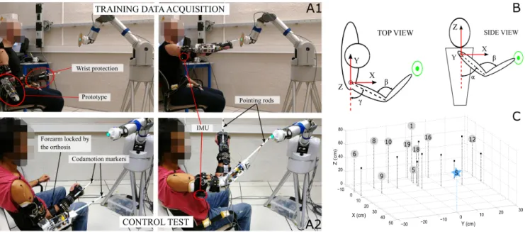
The participants were equipped with a prosthetic elbow (Fig. 1A), a 1-DoF prototype that was designed based on
the functional characteristics of commercialized active elbow prostheses.
The prototype is made of an aluminum structure with a forearm shape and is actuated by a brushless Maxon geared motor (12V EC-max 30 with a GP32C planetary gearhead with a 159:1 ratio) and a couple of spiral bevel gears (1:1 gear ratio). The prosthetic elbow prototype is able to generate a joint nominal torque of 5.5 Nm at a nominal speed of 250 deg/s (41.7 rpm). It is velocity driven by an EC motor drive Elmo Whistle 2.5/60 (Elmo Motion Control, Ltd.) thanks to an optical encoder (AMT 103, 2048 PPR) placed on the motor rear shaft. The weight of the prosthetic elbow is 745g (without batteries, since it was externally powered during the experiments) and reached 1140g considering the extra weight of the elbow orthosis on which the prosthetic forearm was attached. The orthosis was installed on the subjects such that the prosthesis rotation axis was aligned with the elbow flexion/extension axis.
The prosthesis is controlled by a Raspberry Pi, which controls the motor driver and reads the data from an x-IMU (x-io Technologies, Ltd.) placed on the subject’s arm (Fig. 1A). The inertial sensor measures upper arm orientation represented as quaternions using the embedded sensor fusion algorithm AHRS (Attitude Heading Reference System) [23]. The x-IMU is reset at the beginning of each experimental session, and its position remains unchanged during the whole experiment. The IMU data output rate is 256 Hz.
B. Experimental setup
The experimental setup is illustrated in Fig. 1A where the subjects are pointing at targets while sitting on a chair. The participants wore a wrist splint, designed for sport activities, to prevent wrist flexion. They used a rod rigidly attached to the wrist splint’s back or to the prosthesis to reach the targets. The targets were represented by a bright push button mounted on a 7-DoF robotic arm (WAMTMarm, Barrett Technology, Inc.); they were randomly presented to the subjects, who could not predict the target locations since they were shown only one at a time.
For analysis purpose (since control uses exclusively IMU data), upper limb motion was recorded with a camera-based motion capture system, Codamotion (Charnwood Dynamics, Ltd.), with an acquisition frequency of 100 Hz. Two cameras and 8 markers were used in the setup: 7 markers were placed on the subjects’ arm and forearm, the eighth marker measured the prosthesis rod position, as depicted in Fig. 1A2. C. Experimental protocol
1) Acquisition of training data: During the first part of the experiment, the task was to point at 19 targets located in front of the subjects. In order to account for the constant distance between the two pointing rods (Fig. 1A2), the subjects were asked to reach a target located on the left border of a disk which was centered on the WAM robotic arm target (Fig. 1A). Targets were located within a workspace of size 20x60x60 cm3, as shown in Fig. 1C. Subject-robot
Fig. 1. A: Experimental setup. The elbow prosthesis, to which an IMU is connected, was mounted on an upper limb orthosis attached to the participants’ arm and forearm. The subjects were pointing at a target with a rod rigidly attached to a wrist splint during the training data acquisition (A1) or to a prosthetic elbow prototype fixed to his arm during the control test (A2). The target was presented to the subject by a WAM robotic arm. The subjects were equipped with Codamotion markers. B: Anatomical angles γ, α, β describe the upper limb posture. C: Positions of the 19 targets to which the subjects pointed at during the trials. The star-shaped marker denotes the shoulder location. Kinematics information from numbered targets was included in the training data set.
subjects could reach all targets. The subjects were asked not to move their trunk during the experiment, but were not physically constrained. The starting position, to which they had to come back after every movement, was defined after all sensors were placed on the subjects: the participants were sitting on a chair, with their forearm resting on the armrest (Fig. 1A). Since inter-joint coordinations are influenced by the external weight applied on the upper limb segments, the prosthesis was attached to the subjects even during the training data acquisition (Fig. 1A1), but in an inactive mode (locked into an extended position). No particular instruction on movement duration or speed was given to the participants. For each target, the subjects stayed for 2 seconds at the starting position, went towards the target, pushed the button with the rod tip, stayed immobile for 2 seconds, and went back to the starting position, while the WAM robotic arm was moving its end effector to the next target location. During this first part, the IMU was connected to a computer to record arm kinematics while the participants performed natural pointing movements. One trial of 19 pointing movements was performed three times.
2) Building the RBFN-based regression model: Data from the two measurement systems, Codamotion and IMU, were synchronized offline. In order to describe the arm posture, the shoulder and elbow angles introduced in [24] and illustrated in Fig. 1B were utilized with the following notation: γ, the direction angle, characterized the humerus pointing direction, α, the inclination angle, represented the angle between the humeral longitudinal axis and the trunk vertical axis, and β described the elbow flexion angle. For instance, the angular configuration (γ,α,β) is (0,90,0) deg in right lateral shoulder
abduction with maximal arm extension.
Shoulder angles were derived from x-IMU data, while the elbow angular position was derived from the Codamo-tion system. Shoulder and elbow angular velocities were numerically computed from angular position measurements. An RBFN-based regression, described in [25] and imple-mented in a Matlab script, was performed offline to model the inter-joint relationship between ( ˙γ, ˙α) and ˙β, using the kinematic information from 10 out of the 19 targets (Fig. 1C). Building the inter-joint coordination model comprises two offline steps: the training phase that uses a training data set (measured set of triplets ( ˙γ, ˙α, ˙β)) from 2 out of 3 trials to approximate the nonlinear function that relates shoulder kine-matics to the elbow angular velocity, and the testing phase that uses the approximated function and measured shoulder kinematics ( ˙γ, ˙α) from the remaining trial to estimate offline the elbow angular velocity. The training data set that yielded the best offline estimation results was selected to build the online model.
3) Control of prosthesis: The model built with the training data set was used as a control law for the prosthesis motor. During the second part of the experimental session, the IMU was connected to the prosthesis controller that ran the em-bedded RBFN-based regression algorithm: based on training parameters, the control algorithm converted the inertial data into a desired elbow angular velocity value that was sent to the motor controller. The participants forearms were blocked into a constant position with the lockable elbow orthosis; hence, only their arm, which the prosthesis was fixed to, was mobile (Fig. IA2). The subjects pointed at the same targets as previously using a rod that extended the prosthetic forearm
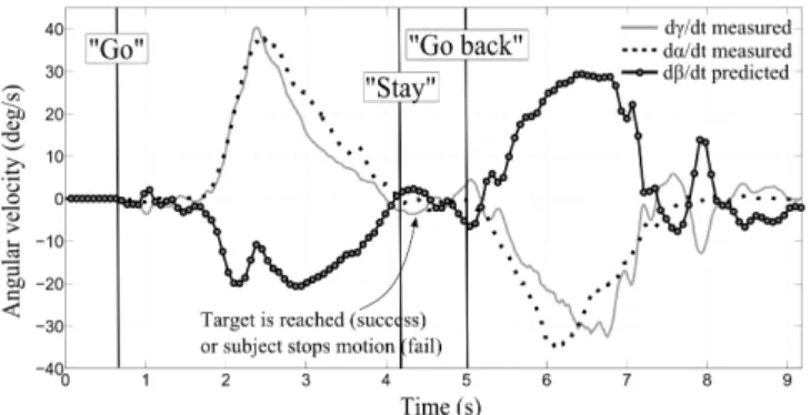
(Fig. 1A2). They received the instruction to bring the rod tip the closest to the target by moving their arm, and if they could, to press the button. For each target, the subjects started the movement, went toward the target, stayed immobile for 2 seconds (Fig. 2), then came back to the initial position, and stayed immobile for 2 seconds while the WAM robotic arm moved the target to the next location and the prosthesis came back automatically to the initial position, chosen at the beginning of the control test (Fig. 1A2).
D. Analysis
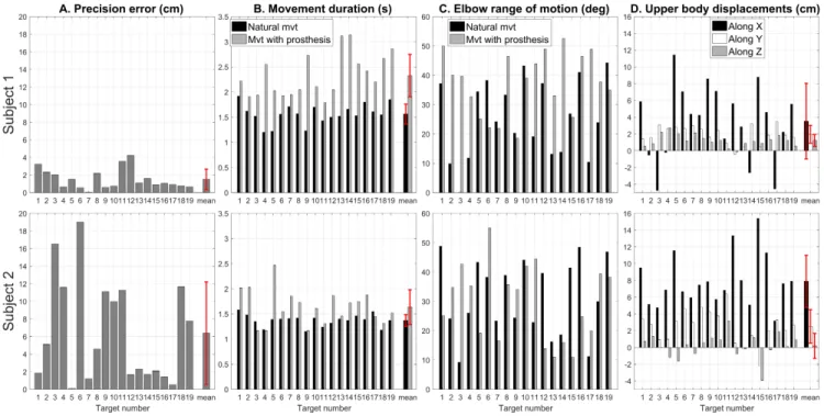
Several metrics were computed to evaluate the subjects performance in controlling the prosthetic elbow to reach the targets. The functional performance of each subject was assessed by the precision error, that was defined as the 3D distance between the tip of the rod attached to the prosthesis and the target when the subjects reached the target or when the movement stopped, and the movement duration, that was the time needed for the subjects to reach the target. The movement duration was also computed for the first training trial, and was used as reference (natural movements). Natural and prosthetic elbow flexion motion were compared, and shoulder, scapula and trunk linear displacements were also analyzed to quantify eventual compensatory movements.
III. RESULTS
A. Offline testing
In the model validation process, the RBFN-based re-gression model was obtained by mapping the IMU shoul-der/Codamotion elbow data from 2 out of the 3 training trials for each subjects, and was used with IMU shoul-der kinematics from the third trial to predict the elbow angular velocity offline. The regression algorithm perfor-mance was assessed by comparing the predicted angular velocities with the Codamotion-based measurements for each target numbered in Fig. 1C. Table I groups the Root Mean Square (RMS) error between measured and estimated elbow angular velocity RM Svel, the relative error between the
peak values of measured and predicted velocities Errpeak,
the RMS error between measured and reconstructed elbow angle from integrated predicted angular velocity RM Spos,
and the relative error between the measured and estimated final angular positions (when the hand reaches the target) Errf inal, averaged over the 3 trials and all targets. The
overall predicted angular position error was less than 15 deg for both subjects, and was equal to 12.6% ± 6.6% for Subject 1, and 18.4% ± 14.5% for Subject 2, of final elbow position. B. Online control test
Each subject was asked to use the prosthesis to point at targets while their forearm was locked into a fixed position. The RBFN-based regression algorithm computed in real time the elbow angular velocity using the training parameters and the shoulder angular velocity ( ˙γ, ˙α) derived from the online IMU measurement. The calculated elbow angular velocity was sent as control signal to the motor controller; an instance
Angular velocity errors Angular position error RM Svel(deg/s) Errpeak(%) RM Spos(deg) Errf inal(%)
Subject 1 13.2 ± 3.11 32.97 ± 12.5 7.96 ± 2.04 12.48 ± 6.55 Subject 2 11.9 ± 4.78 28.74 ± 19.08 11.4 ± 8.85 18.43 ± 14.47
TABLE I
OFFLINE VALIDATION:RESULTS OF COMPARISON BETWEEN ESTIMATED AND MEASURED ELBOW ANGULAR VELOCITY
of ( ˙γ, ˙α, ˙β) from one reaching movement with prosthesis is depicted in Fig. 2.
The task performance was assessed with the precision error and the duration time. The precision error (Fig. 3A) between the position reached by the prosthesis end tool and the target, averaged over all targets, was 1.5 cm ± 1.2 cm for Subject 1, and 6.4 cm ± 5.8 cm for Subject 2. For each target, the time needed to reach the target with the rod attached to the prosthesis (control test) and the time needed to reach the target with the rod attached to the hand (natural movements) are calculated and the values are depicted in Fig. 3B. The overall time to reach a target naturally was 1.56 s ± 0.20 s for Subject 1, and 1.37 s ± 0.12 s for Subject 2, while using the prosthesis, the duration time was 2.33 s ± 0.42 s for Subject 1, and 1.64 s ± 0.35 s for Subject 2.
Elbow ranges of motion were computed for both types of movements: the elbow flexion angle varied between 0.02 deg and 44.3 deg for Subject 1 (resp. between 9.2 deg and 48.8 deg for Subject 2) during natural pointing movements, and varied between 18.6 deg and 52.6 deg (resp. between 11.1 deg and 55.0 deg) when the prosthesis was used for the pointing task. Difference values between final and initial elbow angle are depicted in Fig. 3C. The shoulder displacements were analyzed with the motion capture system recordings during natural pointing movements and reaching movements using the prosthesis. Natural movements and movements when the subjects are controlling the prosthesis were first processed separately: for both types of movements, the 3D shoulder displacement, calculated between initial and final positions (see Fig. 1A), was defined as dnatural =
Fig. 2. Embedded algorithm’s inputs and output signals for one movement of Subject 1 toward target 19. The IMU-based shoulder angular velocities measurements (solid grey and dotted black lines) are utilized by the RBFN-based regression algorithm to compute online the elbow angular velocity (solid line with round markers).
Fig. 3. Reaching task assessment for the two participants. Movements are compared to natural movements from the first training trial, and results show that the movement strategy is changing when pointing at targets using a prosthesis.
Mf inal− Minitial, dprosthesis = Mf inal− Minitial, where
Minitial ∈ R3 (resp. Mf inal ∈ R3) denoted the shoulder
marker position when the subjects started the movement (resp. reached the target or stopped the movement), and dnatural∈ R3 (resp. dprosthesis ∈ R3) denoted the distance
between initial and final shoulder positions when the subjects reached the target naturally (resp. when the subjects used the prosthesis to point at one target). The value dshoulder∈ R3,
defined as dshoulder = dprosthesis− dnatural, represented
the difference between the shoulder displacement during a natural movement and the shoulder displacement while controlling the prosthesis. The values are depicted in Fig. 3D. Averaged over all movements, the displacement along the forward direction (X axis) was 3.5 cm ± 4.5 cm for Subject 1, and 7.9 cm ± 3.1 cm for Subject 2.
IV. DISCUSSION
Two healthy participants succeeded in using a prosthetic elbow, on which their own inter-joint coordination model was implemented as control law, to reach targets in a 3D workspace. The control law was modeled based on record-ings of healthy pointing movements prior to the control test using a RBFN-based regression method. To the authors’ knowledge, this is the first reported automatic control im-plementation that uses IMU-based input signals and upper limb inter-joint coordination to control a prosthetic elbow. The approach to build the inter-joint coordination model was chosen to be realistic: the present setup had 19 testing targets, 10 of which were also used for training the algorithm. The fact that the subjects could point at targets that were not included in the training data set demonstrate the spatial generalization property of the presented control method. The
precision error was very encouraging for Subject 1 (less than 2 cm, knowing that the target diameter itself was 2 cm).
It is clear from Fig. 3 that the two participants performed differently when using the prosthesis: Subject 1 succeeded in reaching 16 targets out of 19 with an overall error of 1.5 cm ± 1.2 cm, while Subject 2 reached 9 targets with an overall error of 6.4 cm ± 5.8 cm. Although movement durations were similar for both subjects during natural reaching move-ments, they increased more for Subject 1 than for Subject 2 when both used the prosthesis to point at the targets. This suggests that Subject 1 adapted his behavior to the task by slowing down his arm motion. There is an important difference between the ranges of motion of the natural and the prosthetic elbow, supporting the fact the subjects used different strategies to achieve the task by controlling the prosthesis. The shoulder displacement analysis confirm this hypothesis. The difference in shoulder displacements during natural movements and movements with the prosthesis are dominant in the forward direction: there is more shoulder forward motion when the subjects use the prosthesis to achieve the task. Subject 2, who did not adjust his motion timing, modified his upper body motion in order to reach a target: the difference of shoulder displacements along the X-axis during natural movements and movements with the prosthesis is 3.5 cm ± 4.5 cm for Subject 1, and 7.9 cm ± 3.1 cm for Subject 2.
Natural reaching movements are usually decomposed in two phases: at first, the Central Nervous System (CNS) controls in an open-loop manner the hand such that it reaches approximately the desired location, then a fine, slower, closed-loop control permits the individual to adjust precisely
the hand’s position and orientation. It seems that Subject 2, even though he was not performing natural movements anymore, used this ballistic strategy to control his upper arm to reach a target: his movement duration were similar to natural times, and the compensatory strategy proves that the upper body was involved to compensate for a mismatch between prosthesis motion and expected forearm motion. A more careful control of prosthesis end tool was applied by Subject 1 who slowed his upper arm motion; since the targets could be reached with the prosthesis, less compensatory movements were needed. Further analysis of compensation strategies will be developed in the future work.
V. CONCLUSIONS AND FUTURE WORK
In this study, healthy individuals succeeded in using a prosthetic forearm (motorized elbow to which was attached a pointing rod) to reach targets in a 3D workspace; the prosthetic elbow motion responded automatically to the subjects’ upper arm motion. To this aim, an inter-joint coordination model from the subjects was implemented on the prosthesis controller that relied on the signals of an IMU, hence removing the constraints related to myoelectric control; the IMU will be directly attached to the prosthesis socket in future designs. The presented control strategy is intuitive since the prosthesis is controlled by a model of natural upper arm movements. The participants recruited in this study did not learn how to control the prosthesis prior to the experimental session: the reported results correspond to their first and only trial. Therefore better results could be expected with short training. In future studies, more IMUs will be involved in the control method in order to be robust to body movements such as walking or bending. In addition, a quantification of the effects of inertial sensors drift will be performed.
Since the inter-joint coordinations cannot be modeled on transhumeral amputees, future efforts will also be focused on the determination of a generic model that will be used with patients. This automatic control method yields promising re-sults, and could be combined with conventional end-effector myoelectric control to achieve simultaneous control of hand and elbow. Therefore, future investigations will involve more generic ADLs including grasping.
REFERENCES
[1] J. T. Belter, J. L. Segil, A. M. Dollar, and R. F. Weir, “Mechanical design and performance specifications of anthropomorphic prosthetic hands: a review,” J. Rehabil. Res. Dev., vol. 50, no. 5, pp. 599–618, 2013.
[2] E. Biddiss and T. Chau, “Upper-limb prosthetics: critical factors in device abandonment,” Am. J. Phys. Med. Rehabil., vol. 86, no. 12, pp. 977–987, 2007.
[3] C. Castellini, P. Artemiadis, M. Wininger, A. Ajoudani, M. Alimusaj, A. Bicchi, B. Caputo, W. Craelius, S. Dosen, K. Englehart, et al., “Proceedings of the first workshop on peripheral machine interfaces: going beyond traditional surface electromyography,” Front. Neuro-robot., vol. 8, 2014.
[4] E. Scheme and K. Englehart, “Electromyogram pattern recognition for control of powered upper-limb prostheses: State of the art and challenges for clinical use,” J. Rehabil. Res. Dev., vol. 48, no. 6, p. 643, 2011.
[5] K. Østlie, R. J. Franklin, O. H. Skjeldal, A. Skrondal, and P. Magnus, “Musculoskeletal pain and overuse syndromes in adult acquired major upper-limb amputees,” Arch. Phys. Med. Rehabil., vol. 92, no. 12, pp. 1967–1973, 2011.
[6] D. S. Gonz´alez and C. Castellini, “A realistic implementation of ultrasound imaging as a human-machine interface for upper-limb amputees,” Front. Neurorobot., vol. 7, 2013.
[7] R. L. Abboudi, C. Glass, N. Newby, J. Flint, W. Craelius, et al., “A biomimetic controller for a multifinger prosthesis,” IEEE Trans. Rehabil. Eng., vol. 7, no. 2, pp. 121–129, 1999.
[8] M. Kuttuva, G. Burdea, J. Flint, and W. Craelius, “Manipulation practice for upper-limb amputees using virtual reality,” Presence (Camb), vol. 14, no. 2, pp. 175–182, 2005.
[9] J. Silva, W. Heim, and T. Chau, “A self-contained, mechanomyography-driven externally powered prosthesis,” Arch. Phys. Med. Rehabil., vol. 86, no. 10, pp. 2066–2070, 2005. [10] Y. Losier, K. Englehart, and B. Hudgins, “Evaluation of shoulder
complex motion-based input strategies for endpoint prosthetic-limb control using dual-task paradigm,” J. Rehabil. Res Dev., vol. 48, no. 6, p. 669, 2011.
[11] R. D. Lipschutz, B. Lock, J. Sensinger, A. E. Schultz, and T. A. Kuiken, “Use of a two-axis joystick for control of externally powered, shoulder disarticulation prostheses,” J. Rehabil. Res. Dev., vol. 48, no. 6, p. 661, 2011.
[12] J. Soechting and F. Lacquaniti, “Invariant characteristics of a pointing movement in man,” J. Neurosci., vol. 1, no. 7, pp. 710–720, 1981. [13] M. Desmurget and C. Prablanc, “Postural control of three-dimensional
prehension movements,” J. Neurophysiol., vol. 77, no. 1, pp. 452–464, 1997.
[14] Y. Paulignan, C. MacKenzie, R. Marteniuk, and M. Jeannerod, “The coupling of arm and finger movements during prehension,” Exp. Brain Res., vol. 79, no. 2, pp. 431–435, 1990.
[15] A. Roby-Brami, N. Bennis, M. Mokhtari, and P. Baraduc, “Hand orientation for grasping depends on the direction of the reaching movement,” Brain Res., vol. 869, no. 1, pp. 121–129, 2000. [16] F. Lacquaniti and J. F. Soechting, “Coordination of arm and wrist
motion during a reaching task,” J. Neurosci., vol. 2, no. 4, pp. 399– 408, 1982.
[17] F. Montagnani, M. Controzzi, and C. Cipriani, “Exploiting arm posture synergies in activities of daily living to control the wrist rotation in upper limb prostheses: A feasibility study,” in EMBC, pp. 2462–2465, 2015.
[18] H. Vallery and M. Buss, “Complementary limb motion estimation based on interjoint coordination using principal components analysis,” in Computer Aided Control System Design, pp. 933–938, 2006. [19] R. R. Kaliki, R. Davoodi, and G. E. Loeb, “Evaluation of a noninvasive
command scheme for upper-limb prostheses in a virtual reality reach and grasp task,” IEEE Trans. Biomed. Eng., vol. 60, no. 3, pp. 792– 802, 2013.
[20] S. D. Iftime, L. L. Egsgaard, and M. B. Popovi´c, “Automatic determi-nation of synergies by radial basis function artificial neural networks for the control of a neural prosthesis,” IEEE Trans. Neural Syst. Rehabil. Eng., vol. 13, no. 4, pp. 482–489, 2005.
[21] M. Popovi´c and D. Popovi´c, “Cloning biological synergies improves control of elbow neuroprostheses,” IEEE Eng. Med. Biol. Mag., vol. 20, no. 1, pp. 74–81, 2001.
[22] M. Merad, A. Roby-Brami, and N. Jarrass´e, “Towards the imple-mentation of natural prosthetic elbow motion using upper limb joint coordination,” in BIOROB, pp. 829–834, 2016.
[23] S. O. Madgwick, “An efficient orientation filter for inertial and inertial/magnetic sensor arrays,” Report x-io and University of Bristol (UK), 2010.
[24] J. F. Soechting, C. A. Buneo, U. Herrmann, and M. Flanders, “Moving effortlessly in three dimensions: does donders’ law apply to arm movement?,” J. Neurosci., vol. 15, no. 9, pp. 6271–6280, 1995. [25] F. Stulp and O. Sigaud, “Many regression algorithms, one unified