HAL Id: hal-00942225
https://hal.archives-ouvertes.fr/hal-00942225
Submitted on 4 Feb 2014
HAL is a multi-disciplinary open access archive for the deposit and dissemination of sci-entific research documents, whether they are pub-lished or not. The documents may come from teaching and research institutions in France or abroad, or from public or private research centers.
L’archive ouverte pluridisciplinaire HAL, est destinée au dépôt et à la diffusion de documents scientifiques de niveau recherche, publiés ou non, émanant des établissements d’enseignement et de recherche français ou étrangers, des laboratoires publics ou privés.
Real-time self-mixing interferometric laser sensor for
embedded applications
doi:10.1088/1757-899X/51/1/012016
Usman Zabit1, Olivier D Bernal2, 3 and Thierry Bosch2, 3
1
Riphah International University, Islamabad, Pakistan
2
CNRS, LAAS, 7 avenue du colonel Roche, F-31400 Toulouse, France
3
Univ de Toulouse, INP, LAAS, F-31400 Toulouse, France E-mail: [email protected]
Abstract. A Self-Mixing (SM) interferometric laser displacement sensor is presented that is capable of providing correct target measurement in real-time even when it is subject to extraneous parasitic movements. The sensor achieves such robustness by using an embedded MEMS Solid-State Accelerometer (SSA) that has been coupled with the laser sensor. The SSA thus measures the extraneous movement acting on the laser sensor and this information is used to provide correct sensing. The proposed SSA-SM sensing system uses Consecutive-Samples based Unwrapping (CSU) to process the SM interferometric signal while a Digital Signal Processor (DSP) takes care of band-pass filtering, double integration as well as phase and gain corrections needed for the acceleration signal. Hence, a compact, real-time, precise and self-aligned SSA-SM sensor has been designed that has a displacement measurement precision of approximately 100 nm with a parasitic movement elimination of 31dB for a laser diode emitting at 785 nm.
1.Self-mixing interferometry
Self-mixing (SM) or optical feedback interferometry technique has been regularly investigated during the last two decades [1-3] for distance [4], velocity [5], vibration [6] and displacement [7] sensing applications as it results in a simple, compact, self-aligned, and low-cost sensor that becomes attractive not only for industrial use but also for large-scale consumer applications [5].
Displacement retrieval using SM interferometry remains a very active area of research [8-10] with applications as varied as run-out tracking in electric motors [9], the displacement measurement of local chest wall [11], or utilization for non-contact embedded sensing [10].
SM effect occurs in a laser when a part of the beam backscattered by a target is coupled back into the laser cavity and causes interference with the emitted beam, thus modifying the spectral properties of the laser. The variations in the optical output power of the laser diode P(t) caused by this optical feedback can be written as [12]:
( )
t
P
[
m
(
x
( )
t
)
]
P
=
01
+
.
cos
F (1)where P0 is the emitted optical power under free-running conditions, m is the modulation index and
(3) where α is the linewidth enhancement factor, and x0(t) is the laser output phase in the absence of
feedback, obtained by replacing λF(t) with λ in (2), where λ is the laser diode emission wavelength
under free running conditions. C is the feedback coupling factor that determines the SM operating regime and is given by [3]
ext L D C γ α κ τ τ 1+ 2 = (4) where τL and τD are the round trip times in the internal and external cavities respectively, γ is the
coupling efficiency and κext depends linearly on the surface reflectivity of the target.
The C parameter plays an important role in the SM interferometry as variations in C cause changes in the so called SM operating regimes varying from weak to moderate to strong feedback [12], where each regime would require specific signal processing for the sake of displacement retrieval [13]. For the present work, care has been taken to maintain the SM signal in the moderate regime with C ranging from 1 to 2 as the resulting SM signal requires simplified processing and is not affected by the fringe-loss issue [14].
SM interferometry is thus a very attractive sensing scheme in the way that it allows a simple laser diode (LD) package (containing its built-in photodiode) to be used as a micro-interferometer, a laser source as well as a detector. This thus allows a compact, miniaturized, low-cost and self-aligned sensor capable of nanometric measurement precision.
Now, it needs to be said that SM displacement sensors have traditionally needed a stationary support (such as an optical table and/or anti-vibration material) to guarantee an accurate target measurement as any parasitic/extraneous movement of the SM sensing laser system can corrupt the true target displacement measurement. Such a situation has thus restricted the use of SM sensors for embedded and/or industrial applications where hostile environment can introduce parasitic extraneous movements.
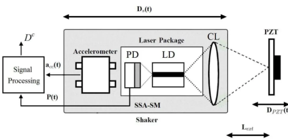
So, keeping in mind such a limitation that can potentially limit the use of such optical sensors, a Solid-State Accelerometer (SSA) coupled Self-Mixing (SSA-SM) sensing system has been recently proposed [15] and evaluated [10] that measures true target displacement even if the laser sensor is itself subject to a displacement (noted as Ds). A schematic diagram of such a SSA-SM sensing system is presented in figure 1. The solid-state MEMS (micro-electro-mechanical system) accelerometer measures the laser sensor displacement and a subsequent subtraction of this displacement from the global (corrupted) SM displacement provides the true target displacement.
In this paper, after a presentation of the signal processing needed for a SSA-SM sensing system, we shall detail the approach taken for the design of a real-time SSA-SM sensing system. An all digital signal processing approach has been developed that takes care of the band-pass filtering, double integration as well as phase and gain corrections required by the acceleration signal. The presented real-time SSA-SM sensor system is based on a LD package from Sanyo (DL7140) emitting at
λ=785nm with an output power of 60mW. The accelerometer LIS344ALH is from ST with a typical noise resolution of 50µg/√Hz and a full-scale range of ±2g. Finally, the results based on this real-time sensing prototype would be presented and compared with a commercial PZT (Piezo-electric Transducer) from Physik Instrumente (P753.2CD) equipped with a built-in capacitive feedback sensor (CFS) of 2nm resolution. The PZT has been used as the target in our set-up (see figure 1) and the CFS has served as a reference sensor.
Figure 5. Schematic block diagram of the Solid-State Accelerometer (SSA) coupled
Self-Mixing (SSA-SM) sensing system: photodiode (PD), laser diode (LD), collimating lens (CL), and piezoelectric transducer (PZT).
Let us now start with a presentation of the signal processing needed for the real-time SSA-SM sensing system capable of removing the influence of extraneous movement acting on it.
2.Signal processing
The signal processing steps considered necessary for a correct working of our SSA-SM sensing system are presented in figure 2. Let us now present each of the three main processing blocks as detailed below.
Figure 2. Schematic block diagram of the signal processing steps needed for the real-time
Self-Mixing interferometric laser displacement sensor with embedded MEMS accelerometer. 2.1.SM Laser Interferometric Signal
The variations in the optical output power of the laser diode P(t) are monitored through the built-in photodiode (PD) contained in the LD package. For real-time SSA-SM sensing system, SM displacement retrieval has been done by using the Consecutive Samples based Unwrapping (CSU) method [16]. This displacement retrieved from the signal P(t) has been denoted here as DΣ since it is
the sum of the true target displacement DPZT and the displacement undergone by the sensor Ds.
The working of CSU method is shown in figure 3. It starts by retrieving the SM based displacement through fringe-counting resulting in an initial precision of λ/2. Then, in a manner similar to the fully analog SM processing method [17], it recovers the target displacement by adding the fringe-counting based staircase signal to the normalized SM signal. So, it is able to retrieve SM based displacement with a precision of approximately λ/8.
through Consecutive-Samples based Unwrapping [15]. (a) normalized SM signal corresponding to C=1.5, (b) fringe discontinuity detection, (c) staircase signal representing the fringe count and (d) the retrieved signal proportional to target excitation signal obtained by the addition of signals (a) and (c).
It may be said that in order to process the SM signal in real-time, the fully analog SM processing technique proposed by Norgia et al [17] may have been considered. However, keeping in mind the non-harmonic nature of DΣ, it is important to use an approach capable of processing non-harmonic
movements without suffering from drift effects. Hence, the SM signal has been processed in real-time using the above-mentioned CSU method.
It may also be added that the SM sensing precision of direct unwrapping approach is lesser than a segmented unwrapping approach, as highlighted by [18]. Recent work has shown as to why such a segmented processing improves the sensing precision [19]. However, this segmented unwrapping approach [18-19] has not been used due to increased processing complexity hindering a real-time sensor design, a condition needed for the present sensor.
For the actual SSA-SM sensing system, an integrated micro-converter AduC7020 from Analog Devices® working at 40 MIPS has been used that has integrated Analog-to-Digital Converter (ADC) and Digital-to-Analog Converter (DAC) modules. The incoming signal P(t) is processed into the output displacement signal D(t) at 125KHz with an approximately λ/8 precision. So, the SM based displacement DΣ is updated every 8µs.
As far as the maximum measurable target speed using this prototype is concerned, the experimental data has shown that 20 samples per SM fringe are normally needed in order to correctly detect the fringe-discontinuity of each SM fringe having its associated noise. This then provides the maximum measurable target speed of 2.45mm/s for the real-time SM signal based displacement retrieval method with the above-mentioned configuration [16].
2.2.Accelerometer Signal
The displacement undergone by the sensor itself (noted here as Ds) is recovered by processing the
acceleration signal provided by the SSA. In order to do so, the acceleration signal acc(t) is filtered and
integrated twice, as indicated in the lower half of figure 2. The band-pass filtering is done over the operating bandwidth of 40Hz-500Hz so that low-frequency drifts that can falsify the subsequent integration steps as well as high frequency acceleration signal saturation can both be avoided.
The choice of a given low cut-off frequency is closely related to the overall SSA-SM sensing system measurement precision. As displacement extraction from acceleration signal involves double integration, so the noise power spectrum density of the displacement SD can be given in the frequency
domain as [15] 4 ) ( ) ( s s S s S acc D = (5)
Consequently, the displacement resolution of the SSA signal depends on the low cutoff frequency of the system. For a 20Hz lower cutoff, LIS344ALH is thus expected to introduce an RMS error of approximately 40nm.
For the actual SSA-SM sensing system, the integration and filtering stages (indicated in figure 2) needed for extracting the displacement Ds from acc(t) signal provided by LIS344ALH have been
implemented on an integrated Digital Signal Processor (DSP) from Microchip®, called the dsPIC33FJ128GP. It has also integrated ADC and DAC modules which allow a simple interfacing. The incoming signal acc(t) is processed into the displacement signal Ds(t) at 10KHz. Such a sampling
rate is sufficiently high to correctly process the acceleration signal of 40Hz-500Hz operating bandwidth.
2.3. Matching of SM signal with Acceleration signal
In order to match the two signals (DΣ and Ds), phase (φ) and gain (G) corrections need to be done. This
is necessary as both signals i.e. the self-mixing signal and the acceleration signal pass through their respective signal amplification, acquisition, and processing stages all of which may introduce differences in phase and gain between the two signals.
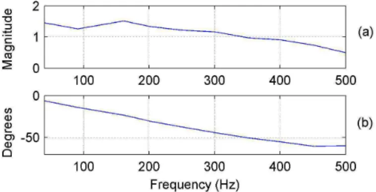
So, in order to measure the phase and gain coefficients between the two displacements signals, the SSA-SM sensor was subjected to vibrations within the 40Hz-500Hz bandwidth. This allowed us to recover the coefficients that have been presented in figure 4.
Figure 4. (a) Gain transfer function and (b) Phase transfer
function between SM based displacement DΣ and acceleration
based displacement Ds. A digital filter having the same Bode
diagram has been implemented on the DSP.
Then, a custom filter was designed based on these coefficients and it was also implemented on our DSP. Such a filter thus allowed us to match DΣwith Ds (see figure 2).
Finally, after this phase and gain matching of the two signals (DΣand Ds), we need only perform
the last step of their subtraction that allows us to obtain the corrected displacement Dc. As the signals DΣand acc(t) are both processed by the DSP, so the subtraction is also done internally by the DSP and
final corrected output Dc is hence provided by the DAC of our DSP. Such a solution thus allows us to recover the corrected displacement in real-time.
3.Experimental results
Let us now look into some of the experimental results for the SSA-SM sensing system. As indicated in figure 1, the SSA-SM sensor was mounted on a mechanical shaker that has been used to generate extraneous movement acting on the SSA-SM sensor. The sensor measured the target displacement (we have used the PZT as target while the CFS has been used as a reference sensor of the target motion) while being subject to these extraneous movements.
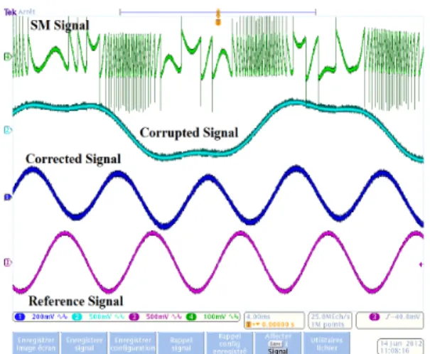
Figure 5. Experimental real-time sinusoidal
target displacement measurement in the presence of an extraneous sinusoidal movement at 40Hz while the target vibrates at 117Hz: (green) SM signal, (light blue) corrupted movement, (dark blue) corrected movement, and (purple) reference sensor movement.
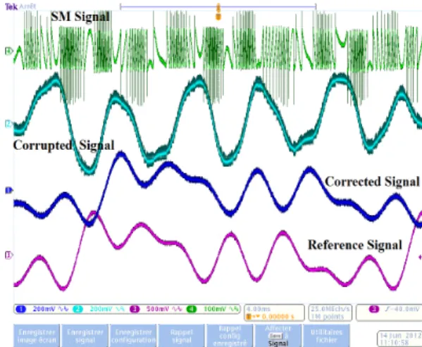
Figure 6. Experimental real-time correction
of an arbitrary target movement corrupted by a different arbitrary movement acting on the SSA-SM sensor: (green) SM signal, (light blue) corrupted movement, (dark blue) corrected movement, and (purple) reference sensor movement.
Subsequently, after this validation, different tests were conducted to verify a correct working of our real-time SSA-SM system for the sake of target displacement measurements. For example, both the shaker and the PZT were excited with either a harmonic or an arbitrary excitation signal.
Figure 5 presents the correction result for the case where the target i.e. the PZT was made to vibrate at 117Hz with an amplitude of 4µm while the extraneous harmonic movement acting on the SSA-SM sensor (provided by the shaker) was at 40Hz. It can be seen in figure 5 (light blue curve) that the corrupted signal i.e. DΣ is not at all indicative of true target movement (seen in figure 5 purple curve).
However, a correct target displacement measurement has been made by our real-time SSA-SM sensing system as indicated by the dark blue curve of figure 5. A close resemblance between the corrected signal and the reference signal is thus seen. The observed phase difference between the corrected and the reference signal is due to the phase difference between the PZT and the CFS and is of no consequence for our sensing application.
Another real-time displacement measurement result is presented in figure 6 where the shaker and the target were both excited by different arbitrarily shaped excitation. The shaker was thus excited with a signal composed of 140Hz-280Hz while the PZT was excited with a signal composed of 31Hz-62Hz-124Hz-155Hz. As a consequence, the displacement DΣ measured by the SM signal is completely
corrupted (figure 6 light blue curve) and is not at all indicative of true target movement (figure 6 purple curve). However, the influence of the extraneous movement disturbing the SSA-SM sensing system has been correctly eliminated by our real-time signal processing which allowed a correct target movement measurement as seen in figure 6 dark blue curve.
Other tests were also conducted that also verified a correct working of our real-time SSA-SM sensing system. figure 7 depicts the case where the target vibration as well as the extraneous vibration are quite close to each other in terms of frequency (79Hz for the target while 83Hz for the extraneous movement). Such a case results in a corrupted signal that appears to be amplitude modulated as seen in figure 7 light blue curve. However, a correct movement has again been retrieved as seen in figure 7 purple curve.
Another interesting case with spectral overlap is presented in figure 8. Here, a test was conducted where the shaker and the PZT were both excited at the same frequency (in this case, 84Hz). Correct results were again obtained in spite of the fact that the target and the extraneous motion have exactly the same frequency. Such a test is important as it validates the working of our sensor for such embedded sensing applications where a mechanical coupling between the target and the sensor may cause the sensor to be subject to extraneous motion at exactly the same frequency as that of the target.
Figure 7. Experimental real-time sinusoidal
target displacement measurement in the presence of an extraneous sinusoidal movement at 83Hz while the target vibrates at 79Hz: (green) SM signal, (light blue) corrupted movement, (dark blue) corrected movement, and (purple) reference sensor movement.
Figure 8. Experimental real-time sinusoidal
target displacement measurement in the presence of an extraneous sinusoidal movement at 84Hz while the target also vibrates at 84Hz: (green) SM signal, (light blue) corrupted movement, (dark blue) corrected movement, and (purple) reference sensor movement.
4.Conclusion
In this paper, a real-time implementation of a Self-Mixing (SM) interferometric laser diode (LD) based displacement sensor coupled with a Solid-State Accelerometer (SSA) has been presented. The said real-time SM displacement sensor system is based on a LD package from Sanyo (DL7140) emitting at λ=785 nm with an output power of 60 mW. The accelerometer LIS344ALH is from ST with a typical noise resolution of 50µg/√Hz. Real-time signal processing has been achieved by an embedded micro-converter and a DSP.
Such an SSA-SM sensor allows measuring correct target movements even when the LD based SM sensor is subject to extraneous movements. This results in a displacement/vibration sensing system that can be used for embedded applications as there is no more need of keeping the sensor stationary. Such an approach opens the way for the use of such laser sensors in conditions where the use of anti-vibration support is not available or possible. The proposed DSP based data fusion between the acceleration signal and the SM interferometric signal enables a robust, compact, real-time and low-cost sensing system.
[1] Donati S 2012 Developing self-mixing interferometry for instrumentation and measurements Laser & Photon. Rev. 6 393417.
[2] Giuliani G and Donati 2005 S Laser interferometry Unlocking Dynamical Diversity: Optical Feedback Effects on Semiconductor Lasers ed D M Kane and K A Shore (Chichester: John Wiley & Sons Ltd) pp. 217-256.
[3] Bosch T, Bes C, Scalise L and Plantier G 2006 Optical feedback interferometry Encyclopedia of Sensors American Scientific Publishers 7 pp. 107–127.
[4] Mourat G, Servagent N and Bosch T 2000 Distance measurement using the self-mixing effect in a three-electrode distributed Bragg reflector laser diode Opt. Eng. 39 738
[5] van der Lee A, Carpaij M, Moench H, Schemmann M and Pruijmboom A, “A miniaturized VCSEL based sensor platform for velocity measurement”, Proc. of the 25th IEEE International Instrumentation and Measurement Technology Conference, pp 141-143, 2008. [6] Giuliani G, Bozzi-Pietra S and Donati S 2003 Self-mixing laser diode vibrometer Meas. Sci.
Technol. 14 24-32
[7] Ottonelli S, De Lucia F, di Vietro M, Dabbicco M, Scamarcio G and Mezzapesa F P 2008 A Compact Three Degrees-of-Freedom Motion Sensor Based on the Laser-Self-Mixing Effect Photonics Technology Letters, IEEE 201360-2
[8] Zabit U, Bernal O D and Bosch T 2013 Self-mixing laser sensor for large displacements: signal recovery in the presence of speckle IEEE Sensors Journal 13 824-31
[9] Atashkhooei R, Urresty J-C, Royo S, Riba J-R and Romeral L 2013 Runout Tracking in Electric Motors Using Self-Mixing Interferometry Mechatronics, IEEE/ASME Trans. doi: 10.1109/TMECH.2012.2226739,.
[10] Zabit U, Bernal O D and Bosch T 2013 Design and analysis of an embedded accelerometer coupled Self-Mixing laser displacement sensor IEEE Sensors Journal 13 2200-7.
[11] Milesi I, Norgia M, Pompilio P P, Svelto C and Dellaca R L 2011 Measurement of Local Chest Wall Displacement by a Custom Self-Mixing Laser Interferometer Instrumentation and Measurement, IEEE Trans. 60 2894-901
[12] Plantier G, Bes C and Bosch T 2005 Behavioral model of a self-mixing laser diode sensor Quantum Electronics, IEEE Journ. 41 1157-67
[13] Zabit U, Bosch T, and Bony F 2009 Adaptive transition detection algorithm for a self-mixing displacement sensor IEEE Sensors Journ. 9 1879–86
[14] Zabit U, Bosch T, Bony F and Rakic A D 2010 A self-mixing displacement sensor with fringe-loss compensation for harmonic vibrations IEEE Photonics Technology Letters 22 410–2 [15] Zabit U, Bernal O D, Bosch T and Bony F 2011 MEMS accelerometer embedded in a
self-mixing displacement sensor for parasitic vibration compensation Optics Letters 36 612-4 [16] Zabit U, Bernal O D and Bosch T 2012 Self-mixing sensor for real-time measurement of
harmonic and arbitrary displacements Inst. and Meas. Techn. Conf. (I2MTC), 2012 IEEE 13-16
[17] Norgia M and Pesatori A 2011 Fully analog self-mixing laser vibrometer Inst. and Meas. Techn. Conf. (I2MTC), 2011 IEEE, pp.1-4
[18] Y. Fan, Y. Yu, J. Xi, and J. F. Chicharo 2011 Improving the measurement performance for a self-mixing interferometry-based displacement sensing system Applied Optics 50 5064–72 [19] Zabit U, Bernal O D and Bosch T 2013 Study of Laser Feedback Phase under Self-Mixing
leading to Improved Phase Unwrapping for Vibration Sensing IEEE Sensors Journ. doi:10.1109/JSEN.2013.2276106