COMPLIANT WATER WAVE ABSORBERS
byJER•ME H. MILGRAM
S.B., Massachusetts Institute of Technology
(1961)
M.S., Massachusetts Institute of Technology (1962)
3UBMITTED IN PARTIAL FULFILLMENT OF THE REQUIREMENTS FOR THE
DEGREE OF DOCTOR OF PHILOSOPHY at the MASSACHUSETTS INSTITUTE OF TECHNOLOGY August, 1965 Signature of Author.
Dprtment of Naval Architecture and Afii ZEngineering, August 20, 1965 Certified by...
Accepted by ...
Thesis Supervisor /
Chairman, Departmental Committee on Graduate Students
ABSTRACT
COMPLIANT WATER WAVE ABSORBERS
by
Jerome H. Milgram
Submitted to the Department of Naval Architecture and Marine
Engineering on August 20, 1965 in partial fulfillment of the requirement for the degree of Doctor of Philosophy.
This report comprises a detailed theoretical and experimental study of the problem of absorbing plane water waves by means of a moving boundary at one end of a channel. The non-linear problem is formulated as a sequence of linear problems by means of perturbation techniques. This formulation is carried out first for a general moving boundary and then for the specific case where the boundary is a hinged paddle above a solid wall. In order to avoid the parameter of the channel length in the theoretical work, this work is carried out for a semi-infinite tank. Solutions for the necessary wave absorber characteristics are determined by the first order (linear) theory. Second order solutions are determined when the incident wave is a plane, periodic, progressive wave. The theoretical developments are done with the neglect of surface tension, but these effects are considered in a separate chapter and they are accounted for in the computer programs used for the design of a wave absorbing system. The problem of synthesizing a wave ab-sorbing system whose characteristics closely approximate an ideal absorber and which can be constructed readily is solved. The solution of this problem
requires a computer-aided design procedure for electric filters which may be of general interest for its own sake, apart from. the remainder of this work. The stability of wave absorbers is examined by a utilization of the theory of waves with complex wave numbers. It is shown that such waves can be constructed as combinations of waves with real wave numbers travelling
in skew directions in the vertical plane of the channel. The absorption of wave pulses is considered. The velocity potential for a wave pulse can be represented as an integral over the normal modes of the absorbing channel
if certain restrictions on the characteristics of the absorber are met. Ex-periments on the absorption of periodic waves and wave pulses were carried
out. In addition an experiment was performed which confirms the theoretical relationship between pressure and surface elevation. This was done as part of an examination of the possibility of activating a wave absorber with a pressure signal in the future.
Thesis Supervisor: Martin A. Abkowitz Title: Professor of Naval Architecture
-ACKNOWLEDGEMENTS
The author wishes to express his appreciation to Professor Martin A. Abkowitz, project supervisor; and Professors Erik L. Mollo-Christensen
and Justin E. Kerwin, project committee members; as well as to the M.I.T. Computation Center which provided the Time-Sharing System on which the computer work was done. The author is also grateful to Block Associates, Inc. whose kind loan of some electronic apparatus facilitated the
experiments, and to Mr. Raymond Johnson whose Shop at M.I.T. fabricated parts of the apparatus.
Special credit is due to Mr. Stanley Chang who did the equation lettering, and to Mr. Donald Yansen who was of great assistance in
constructing the experimental apparatus and in proofreading parts of the theoretical work.
TABLE OF CONTENTS
Subject TITLE PAGE ABSTRACT ACKNOWLEDGEMENTS TABLE OF CONTENTS LIST OF FIGURES LIST OF SYMBOLS CHAPTER 1. CHAPTER 2. CHAPTER 3. CHAPTER 4. CHAPTER 5. CHAPTER 6. CHAPTER7.
CHAPTERCHAPTER
CHAPTER
CHAPTER
CHAPTER 8.9.
10. 11. 12. IntroductionGeneral Formulation of the Problem
Formulation of the Boundary Condition at the Wave Absorber and the Hydrodynamic Moment on
the Absorber When the Absorber is a Hinged Paddle
Solution of the Equations for the First-Order Waves When the Incident Wave is a Plane,
Periodic, Progressive Wave
Solution of the Equations for the Second-Order Waves When the Incident Wave is a Plane, Periodic
Progressive Wave
The Effect of Surface Tension
Synthesis of a Linear Wave Absorbing System Function
Obilque Waves
The Stability of Linear Active Wave Absorbers Determination of the Reflection Coefficient
Absorption of Wave Pulses
Discussion of Theoretical and Experimental Wave Absorber Results
-iv-Page iv ii iii iv vi ix
96
112 116 130142
Subject
CHAPTER 13. Investigation of the Relationship Between Pressure and Surface elevation
CHAPTER 14. Conclusions
REFERENCES
APPENDIX A. Design and Construction of the Experimental Wave Tank
APPENDIX B. Design of the Wave blsorbing Filter APPENDIX C. Wave Height to Voltage Transducer
APPENDIX D. Alterations to the Chart Recorder APPENDIX E. Integral Tables
APPENDIX F. Descriptions and Listings of Computer Programs APPENDIX G. Computer-Aided Design Procedure for the synthesis
of a Rational System Function Which Approximates Prescribed Frequency Characteristics
Page 147 163 165 166 168 187 191 194 200 235
LIST OF FIGURES
Figure Page
1-1 Picture of experimental apparatus 7
1-2 Picture of details of the absorbing 9
end of the tank
2-1 Diagram of the geometry for a general absorber 20 3-1 Diagram of the geometry for a hinged paddle absorber 28 3-2 The change in paddle immersion due to a change 28
in paddle angle
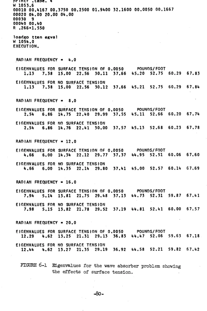
6-1 Computer printout showing the effect of
surface tension on the eigenvalues for 79 the wave absorber problem
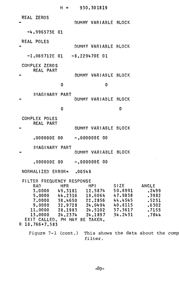
7-1 Computer printout for the synthesis of a comparatively 88 simple wave absorbing system function
7-2 Computer printout for the stability study of the system 90 function synthesized in figure 7-1
7-3 Computer printout for the theoretical determination
of the reflection coefficients for the system function 91 synthesized in figure 7-1.
7-4, 7-5, and 7-6 These figures correspond to figures 7-1, 92
7-2, and 7-3 respectively, where in this 94 case a more complicated system function 95 is considered.
10-1 Diagram of the experiment to measure the 125
reflection coefficient
10-2 Sample record from the experiment to measure 126 the reflection coefficient
10-3 Graph of theoretical and experimental reflection 127 coefficients
10-4 Graphs of the experimental and theoretical 128 system functions
10-5 Diagram of the experiment to measure the 129
system function
11-1 Surface elevation vrs. time for a wave pulse in 140
a channel with an absorber
-Figure
Page
11-2 Surface elevation vrs. time for a wave pulse in 141 in a channel with a 10 degree sloping beach
11-3 Surface elevation vrs. time for a wave pulse in 141 a channel terminated with a solid wall
13-1 Diagram of the experiment to measure the relationship
between pressure and wave height 152
13-2 to 13-10. Graphs of the results of the experiment to 154 measure the relationship between pressure to
and wave height 162
A-i Scale drawing of the wave tank 167
B-1 Representation of an operational amplifier 168
B-2 Simple amplifier circuit 169
B-3 General linear circuit activated by 171
an operational amplifier
B-4 Diagram of the wave absorbing system 184
B-5 Picture.of the gearing between motor,paddle, 185 and feedback potentiometer
B-6 Circuitry around the feedback amplifier 173
B-7 Pole-zero plot for the system function used in 186 the experiments
B-8 e.i4.1 B-99 .Parts of the circuitry used to achieve 177
the desired system function
B-10 through B-13 Parts of the circuitry needed to achieve 181 a more complicated system function than 182
the one which was constructed 183
C-1 Schematic diagram of the circuit for the Wave Height to 190 Voltage Transducer
D-1 Schematic diagram showing alterations to the paper
chart recorder used to attain a high frequency 192 rolloff in the response of the recorder
Figure Page
D-2 Amplitude frequency response for the altered 193
paper chart recorder
G-1 and G-2 Sample computer outputs for the computer-aided 249 design scheme for synthesizing electric filters to
253
-viii-LIST OF SYMBOLS
S- Gradient
-V - Laplacian
x,y - rectangular axis h - depth of water channel
g - acceleration due to gravity 0 - density of the fluid
1 - surface elevation V - velocity
. - velocity potential
t - time
T - surface tension
- horizontal position of the wave absorber
V - component of velocity normal to the absorber at the absorber n
. - perturbation parameter; also used as a small positive number in Chapter 11
p - depth of the pivot for a hinged paddle absorber P - pressure
A - paddle angle, also used to represent wave obliqueness angle in Chapter 8 A - change in paddle imnersion
Mh- hydrodynamic moment on the absorber B - amplitude of sinusoidal paddle motion
a) - radian frequency
A - distance from absorber to end wall of the channel a,v,f - eigenvalues (In Chapter 8, c=fh)
A,B,N,D,G(with subscripts only),R(with subscripts only) - coefficients Hm- ratio of first order moment to first order angle of the paddlem Sh- ratio of first order complex paddle angle to first order complex
rnh(as
subscripts) -non-homogenous
nh(as subscript) - homogenous L - linear operator as defined K - curvature
R - radius of curvature
S=-icito - type of complex frequency usually used by electrical engineers
I INTRODUCTION AND READING GUIDE
This introductory chapter is intended to serve as a guide to the reader as well as to introduce the chapters which follow. Therefore, the bulk of this chapter comprises a compendium of the remainder of this report,
chapter by chapter.
The study reported here concerns the absorption of waves by means of some kind of device which moves in some manner that is controlled by the wave incident upon it. At the outset of this work it was thought that the
absorber would work by moving in response to the force exerted on it by the incident wave; thus the title "Compliant Water Wave Absorbers." However, the wave absorber which was eventually built and tested was actuated by a signal derived from the surface elevation at a fixed point near the ab-sorber. The only previous work done in this field which the author has been able to find is by Baumann (1). In Baumann's work an absorbing paddle is connected to a mass, a spring and a magnetic damper. The various constants were experimentally varied in order to achieve complete absorption at one frequency. For Baumann's absorber, the bandwidth for which the reflection coefficient was less than 10 percent was about five percent of an octave. The absorber reported on here has a bandwidth for which the reflection co-efficient was less than 5 percent of two octaves. Furthermore, the method described herein can be used for any desired bandwidth.
In addition to the direct results of the study of the wave absorbing problem, the experimental work reported here gives further confirmation of the validity of the linearized water wave theory. Some previous work in
of "Forced Small Amplitude Water Waves."
Since wave absorbers can be used in tanks with a wide variety of lengths it is desirable that the tank length not be a parameter in the
theoretical work. Therefore the theoretical work is based on a semi-infinite tank. When waves which are shorter than one tank length are
con-sidered the error in the theoretical reflection coefficient caused by the finite length is negligible. The solution to the initial value problem in a finite tank will be very different from the solution in an infinite
tank although the method of solution and the proof of the existence of a solution is almost identical in the two cases. The finite tank is subject to a type of instability which is not present in a semi-infinite tank. However, if an absorber is stable in a semi-infinite tank, it is also stable in a finite tank provided that it has a reflection coefficient less than unity at low frequencies and the coefficient does not rise too
rapidly with frequency.
In chapter two a general formulation is carried out for an arbitrary
type of absorber (piston, paddle, etc.). The validity of a perturbation series is assumed and equations and boundary conditions for the first and
second order potentials are derived. The development is necessarily very similar 'to other perturbation expansions in this field and need not be
read by the reader who is already familiar with such expansions or is not
interested in them. Chapter three carries out the necessary perturbation
expansions and determines the first and second order boundary conditions
for the case where the wave absorber is a paddle hinged at its bottom a
distance P below the free surface, with a solid •-•ll betwreen th bottom of
-2-the paddle and -2-the bottom of -2-the tank. Expressions for -2-the first and second order hydrodynamic moments on the paddle are also derived in chapter three.
In chapter four the solution of the first order equations subject to first order boundary conditions for a sinusoidal incident wave is carried
out. The problem is reduced to four separate self-adjoint Sturm-Liouville
problems and the solution is given by the resulting eigenfunction series. The coefficients of the series are evaluated for the case where the ab-sorber is a hinged paddle. The linear system function from paddle angle to force is determined such that there be no reflected wave Similarly the linear system function from surface elevation at a fixed point to paddle angle is determined. Since the first order theory is linear, the system having the correct response will absorb a finite sum of sinusoidal waves.
The solution for the second order problem when the incident wave is a plane, periodic progressive wave is carried out in chapter five. The problem is cast in the form of a non-homogeneous linear boundary value problem in which the non-homogeneous terms are non-linear combinations of
the known first order solutions. Because of these terms, a second order absorbing system will not absorb an arbitrary finite sum.of plane periodic, progressive waves.
In the vicinity of the absorber the first order solution contains a wave having a horizontal sinusoidal dependence and a sequence of waves having a vertical sinusoidal dependence. The second order wave resulting from the non-linear interaction of the wave with a horizontal sinusoidal dependence and one of the other waves is interesting. It has a sinusoidal
dependence in a direction which is neither horizontal nor vertical, but rather in a direction which is oblique with respect to the horizontal-vertical frame of reference. The derivation of the second order solution is very long and the resulting expressions are complicated. Therefore, the reading of chapter five is not recommended unless the reader has a
similar problem, wants to design a second order absorber or has a particular interest in the non-linear interaction described above.
Chapter six shows that the effect of surface tension is negligibly
small for the wave frequencies an absorber would usually encounter. The expressions needed to include surface tension effects in the linear theory are determined.
If a wave absorbing system is to be useful, its system function must be a good approximation of that system function which results in complete absorption. The synthesis of a system function which can be built and has
the above characteristics is carried out in chapter seven for the hinged paddle type absorber according to linear (first order) theory. In order
to carry out this synthesis, it was necessary to devise a computer-aided design scheme for synthesizing the system function of an electronic filter.
This scheme is of interest apart from the remainder of this report and is reported briefly in chapter seven and in detail in appendix g.
In chapter eight the theory of oblique waves in a semi-infinite tank is carried out and it is shown that these waves can be represented by the same expressions as more usual waves, except that the wave numbers in the
representation are complex for oblique waves. When oblique waves satisfy a homogeneous free surface condition . is shown that the frequency must
decreases with time. Such waves must be used in a consideration of the
stability of a wave absorbing system with respect to negative going waves; this being the topic of chapter nine. Normal modes with complex frequencies must be used for the solution to the initial value problem in a finite
tank, but theoretical problems in a finite tank are not considered in this report. Chapters eight and nine constitute a study of the stability of a servomechanism in which the feedback is provided by a hydrodynamic element (the region of the tank between the paddle and the wave measuring probe).
If the wave absorbing system had the exact system function calculated in chapter four, there would be no reflected wave according to linear theory. Since the synthesized system function differs from the exact
system function there will be a reflected wave in theory, the reflection coefficient varying with frequency. When an experimental system is built its system function will vary slightly from the synthesized function
resulting in a different set of reflection coefficients. The above topics are considered in chapter ten. Also, the results of experiments with the absorber are reported in chapter ten. In most instances the difference
between measured and theoretical reflection coefficients was about 1 percent. The solution to the initial value problem for the semi-infinite tank is considered in chapter eleven. A set of conditions on the behavior of the absorbing system function sufficient for the validity of a given repre-sentation of the solution are determined. Some interesting qualitative experiments on the absorption of wave pulses were carried out and are reported in chapter eleven. A discussion of theoretical and experimental wave absorber results constitutes chapter twelve.
-5-An interesting possibility is to actuate a wave absorber by a signal derived from a measurement of the pressure at a tap in the tank wall. In order to confirm the theoretical relationship between pressure and surface elevation an extensive series of experiments was performed. These experi-ments do indeed confirm the theoretical relationship. The investigation of this relationship is reported in chapter thirteen.
Appendix A contains a brief description of the experimental wave tank as well as a scale drawing of the tank. Appendix B considers the design of the actual electric circuits needed to achieve the synthesized wave absorber system function. These are active electric circuits, being
activated by operational amplifiers. Appendix B contains a short descrip-tion of the operadescrip-tional usage of operadescrip-tional amplifiers for the reader who is unfamiliar with these devices. The design of two synthesized system functions is carried out, the more complicated circuit having a lower reflection coefficient than the simpler circuit of the two. The simpler circuit was built and tested in the experimental work.
Appendix C contains a description of the wave measuring probe and its associated circuitry. This wave measuring device performed very well over
a wide range of wave heights and even gave excellent results for waves which were less than 1/20 of an inch in height.
Ap]iendix D describes the alterations which were made to the paper chart recorded used in the experiments in order that it would filter out
high frequency noise.
Appendix E is a table of the integrals needed in chapters four and five. Appendix F contains brief descriptions of the most important computer
J-6-programs used in this work. It is not intended that these descriptions
be sufficient to inform the reader how to use the programs, but rather that they are intended to serve as a reference to one who is somewhat
familiar with the programs. An exception to this is the computer program IMERG which is described in detail in appendix G. This program, which is
used to synthesize electric filters for prescribed magnitude and phase
characteristics may be of considerable general interest for its own sake. The following figures in this chapter show the experimental apparatus.
FIGURE 1-1 Overall view of experimental apparatus. At right hand end is the wavemaker and the wave-maker control as well as the towcord motor and its control. The apparatus at the left hand end
is labeled in the succeeding figures.
-8-tank
6 fra wall
FIGURE l-2a Detailed view of apparatus at absorbing end of the wave tank. The various components are labeled on the next page.
GENERAL FORMULATION OF THE PROBLEM
The geometry of the problem is based on a "semi-infinite" tank containing a fluid of mean depth, h, as shown in Figure 2-1. Two-dimensional plane progressive surface waves, propagating from left to right in Figure 1 are to be absorbed. A fixed two-dimensional coordinate system is used with the x-axis horizontal and positive to the right. X 0 corresponds to a plane which will be the limiting position of a wave
absorbing device as the wave amplitude tends to zero. x = ! corresponds to the right-hand end wall of the tank shown in Figure 2-1. The y axis is vertical and positive upwards. y = 0 corresponds to the "still water line" and y = -h corresponds to the bottom of the tank. The surface position is denoted by ' (x,t).
The fluid flow is assumed to be frictionless and irrotational so that:
17
(2-1)=
l
0
(2-2)
The boundary conditions are:
1. There can be no component of flow normal to the bottom of the tank at the bottom of the tank:
0=
0
(2-3)
-10-Fluid particles which are on the free surface at any time, are on the surface at all times (this is equivalent to re-quiring that the component of fluid velocity normal to the surface, when measured in a reference frame attached to the surface, be zero):
This is known as the kinematic free surface condition.
3. Newton's Laws and therefore, Bernoulli's equation, applies to particles on the free surface upon which the pressure is assumed to be constant:
This is known as the dynamic free surface condition.
4. Considering the horizontal position of the wave absorber to be (y,t); V the component of velocity of the absorber normal
n
to the absorber itself must be equal to On1 the component x =
5. At the end wall of the tank, the horizontal component of fluid velocity must be zero:
00
()
(2-7)The problem will now be formulated by means of a perturbation
theory in which it is assumed that the following series are valid:
(,Zyy%
f)
+6
CZ..
(2-8)(2-9)
4
C
,t
)
e
4
yt)6
+y,)...
(2-10)It is not known a' priori whether or not the mathematical problem being considered yields solutions for #, p and 5 which are analytic in in the neighborhood of E = 0; and even if the expansions were valid the
"radius of convergence" of the series would be unknown. However, because of the success of this technique in similar problems, it will be carried
out here and the theoretical results then compared with experimental
results. Equations for quantities of order (1) and (2) will be determined.
-12-By using the perturbation series for 0, Laplace's equation (2-2) becomes
EV79
+t
C
(2?..
=0
(2-11)
For 0 to be analytic in E in the
of each power of G in eq. (2-11)
neighborhood of E = 0 the coefficient must be zero.
=
0
,
Sc(2-13)
(2-13)
0 is a harmonic function of x and y throughout the fluid so Ox and Oy can be expanded in power series in y about y = 0. The existence of a power series in y for Ot is assumed.
The various series expansions for terms needed in the boundary conditions at the free surface are:
=
ur ·
+
h
JL
+ ..(2-14)
7 Z0=
0
1.-=
-
I-o
+77
(2-15)
:::lubstitution of the pertirbation series expansions into equation (2-15) results in:
C1I
d m( I(a
,
itVIZ
(S2)
+
+t= e
- ~x;)ifI.
+. ((2-17)
(2-18)Substitution of the preceding expressions into the dynamic free surface condition gives:
6 (
a1
10+
5 a)]
+ 17
0
le't I
I~~~
.O
5
=05
0
(?-19)
As in the case of Laplace's equation, the coefficient of each power of E
must be zero giving:
-14-el 11SO
Ot I
V
0 a);)
I XOy)
I
tP
(2)
57 +637
+p
" o,
'Vt
S
Insertion of the series expansions for the various terms in the free surface kinematic condition along with the assumed requirement of analyticity
in e around E = 0 gives:
7t1
) -$my=0
-(2-22)
m'
0
Combining equations (2-20) and (2-22) gives:
(O
+3 ~).=
(2-23)
(2-24)
Combining equations (2-21) and (2-23) gives:
V
r"I
(2-20)
Is*+9
(2-21)
,;'a"
(D
MA"~
Ve+ý0
1s
+j S
(I)b~ J..
r
~~-7/
0a
-W
";
ý
45
)
4
7
a
Mc
a)
0; ýt i550 (2-25)Substitution of equations (2-20) and (2-22) into (2-25) gives:
°
'i~'
I
13s.
(2-26)
Similarly the lower boundary condition becomes:
=0
(2-27)Also
e boundary
at x =0
condiion
Also the boundary condition at x = I becomes:
(2-28)
O't
01)F"
and0;"?
0
5 1
(1
and=0
=0
(2-29)(2-30)
-16-( ,O
t t-/
( )
w
) I
ý
II ~
rctfl
M
a)
All
57 --
z-,-O
it) a)-~
r
It is assumed that the wave absorber motion can be expanded as:
Z7JZ
(2-31)
and since 0 is a harmonic function, it is known that
=1•O-X
0
+
lZ +.* .(2-32)
Thus the boundary condition at the absorber, equation (2-6), becomes: (2-33)
(0I
so
fi
(2-34)For convenience the preceding equations are regrouped and renumbered:
0
( ) O (2 -3f
Ct"+
5"')
ý soLjP,l
·-
A
/b1ve
5) (2-36) (2-37) (2-38) ~$1o OW %,-, (2-39)Yrr·V-sYnfl)lyt~
04, %.2
~ 1IL~'-~~I
0
a =
(2-42)
=
E(2-43)
"The perturbation expansion yields a homogeneous boundary value problem, equations (2-35) through (2-39), for the first order quantities
( and (1) and a non-homogeneous boundary value problem, equations (2-40) through (2-43), for the second-order quantities (Z)
: G(2) and (2) . The non-homogeneous terms are quantities involving
first-order quantities. Similarly, if the third-order problem were
formulated, the non-homogenous terms would contain first and second order
quantities, and so forth. By sequentially solving first, second, third....
order equations, the solution to the problem can be obtained if the per-turbation series converge. In order to carry out the above scheme the general form of the absorber motion must be known. For the specific
-18-example solved in the following chapters and upon which experiments were performed, the absorber is a paddle hinged at a distance p beneath the calm free surface position with a solid wall between the bottom of the paddle and the bottom of the tank.
F
i-x
1
FIGURE 2-1 Diagram of general wave absorber geometry.
-20-r :B i; i 7FORMULATION OF THE BOUNDARY CONDITION AT THE WAVE ABSORBER AND THE HYDRODYNAMIC MOMENT ON THE ABSORBER
WHEN THE ABSORBER IS A HINGED PADDLE
Consider a wave absorbing paddle hinged a distance f below the free surface and a solid vertical wall between the bottom of the tank and the paddle hinge at x = 0 as shown in Figure 3-1. The paddle angle 9 is considered to be positive when the paddle lies in the region
0 < x<f. Q(t) is to be chosen such that there is no energy radiating reflected wave.
Let,
(L,
(t)+c)
'·(3-1)
The paddle position is B (y,t)
The normal velocity of the paddle is Vn
low (3-3)
1
Expanding cos in a Maclaurin series in 9 and use of equation (3-1) in equation (3-3) gives:
F
(I, (Z)
(3-4)
4
=4*
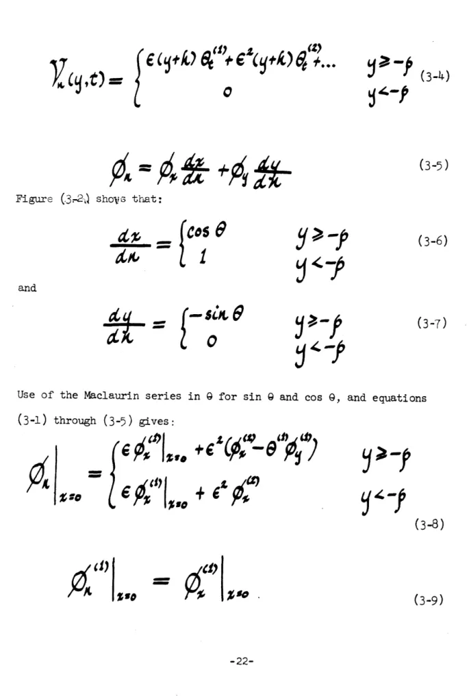
Figure (3.-2ý) shoVe that:
Cos
1
y
>..
-p
(3-6)
and (3-7)0
(3-5)
Use of the Maclaurin series in 9 for sin 9 and cos 9, and equations (3-1) through (3-5) gives: ZI
(6
c~%di~t~
- ,)Yr (3-8)-41) SO
.so.-22-I
(3-9) Ittdk
+6lipl~'_e'"pl;b)
~CL~~fl),w-P
Y"'P
y
> -P
54-'V"
=
{
'
,
I
%s
%10 (3-10) 1,0 +P) Ot'I,O
co"o
c
C9"
4=0
(3-12) (3-13)=i
~ (3-14)Substitution of equations (3-9) and (3-11) into (2-39) gives
(0)
0
IV)Oe
(3-15)Y"~
Y''P
t~~~P
ý,ý
--(3-11)Y~7
YL''P
)7"i~
/
|) o
0,11") lv
Substitution of (3-11), (3-12), (3-13) and (3-14) into (2-43) gives
S0(3-16)
The pressure is denoted by
P
(x,y,t) and the value this function takes on the negative x face of the paddle is called P 1 (y,t) and its value on the positive x face of the paddle is calledP
2 (y,t).The moment exerted by the fluid on the paddle, which is taken as positive when the paddle is pushed toward positive values of x, is denoted
by Mh(t).
C5C
J
[
If
t)-c
t d
(3-17)The pressure is related to the velocity potential by Bernoulli's equation:
p-w
'
C
z
z-5L
)
(3-18)
It is assumed that a perturbation series for the pressure exists.
4
--
-p
g•
J.
(''
..
(3-19)
P
designates either
P1 or
P
2
is a harmonic function of x and y as is Ot for a periodic wave.
Therefore the following expansion for P is valid.
=
p
&fy~&~ZsD
P
(3-20)Substitutions of the various perturbation series into equation (3-18), evaluating the resulting equations at x =
4
= (y + h) 9 and imposing analyticity in e at e = 0 gives the following equations.P
,•p
--
ro
(3-21)
Using the above expressions as well as the Maclaurin series for cos2
gives the following equations for Mt)and 2)
r(3-23
(3-23)
A quantity which will prove useful to know is the ch2ange in immersion of the negative x face of the paddle as the paddle moves in waves. This quantity is called A. The perturbation series for A will nov be determined, using Figure(3-2)as a guide.
t
SCOt,
(3-25)3s
CAs
i/
9(3-26)(3-28)
P 7 +pd
(3-29)
2
D'"='i"l,,
x=O
y=
i7(x,t)
x
paddle pivot-,
9y=-p
08
FIGURE 3-1 Diagram of wave absorber geometry when the absorber is a hinged paddle.
i.
FIGURE 3-2 Diagram showing how the imersed length of an absorbing paddle changes when the paddle angle
is changed.
CHAPTER 4
SOLUTION OF THE EQUATIONS FOR THE FIRST-ORDER WAVES WHEN THE
INCIDENT WAVE IS A PLANE, PERIODIC, PROGRESSIVE WAVE
Introduction
The first-order potential (1) must satisfy equations (2-35) through (2-39). The case considered here is that of a hinged paddle wave absorber so the boundary condition at the absorber is given by
equation (3-15). The first-order potential of a plane, progressive, periodic wave has a sinusoidal time dependence so it is anticipated that the paddle angle necessary to have no reflected energy radiating wave will also have a sinusoidal time dependence.
Let
(1)
The physical variable ) is given by the real part of the above equation. Complex notation is used only as a matter of convenience. Since the
equation and boundary conditions satisfied by the first-order potential are linear, the use of complex variables can and will be carried through the calculations. In order to obtain an equation for a physical quantity at any stage in the following development, it is only necessary to take the real part of the equation under consideration. The solution for the first-order potential is sought in the form of a series, each term of which satisfies equations (2-35) through (2-38) and is separable in the sense that it is the product of three functions, one of x, one of y, and one of t. Such a soluiion to the sinusoidal problem will be found
subsequently and it will be complete in the sense that the function to which the series converges satisfies equation (3-15). Each of the terms
in the series is to be of the form:
In order that e satisfy Laplace's equation (Equation 2-35), F and G e
must satisfy:
--
(4-4)
F and G are subjected to the following boundary conditions:
i;'
:'o
rt
z..[
(4-R)
I-SO t(4-6)
mow-
Z(4-8)
It is also required that the complete solution for ) satisfy equation (3-15).
Since there is a specified boundary condition at x = 0, the problem becomes two problems, one for the potential for--O,; .4 and one for O0 x I.
-30-The problem has thus been recast into four Sturm-LionYl1e-pzrobl~es, one
for F and one for G in each of the regions -00 < x 4 0, and 0, x• L. The solution to equation (4-4) is:
'C)
C.~
(4-9)
To satisfy equation (4-5):
Cl
z
cle
(4-1o)For real values of a equation (4-6) is satisfied if:
AMW Aa ift tax
x
(4-11)To consider imaginary values of U, let:
Oc =Coto (4-12)
where C is real. In this case, equation (4-6) is satisfied if:
W (4-13)
Equation (4-11) yields an infinite number of eigenvalues and
equation (4-13) yields a single positive eigenvalue and a single negative eigenvalue. The solutions to equations (4-11) and (4-13) are both
positive and negative. For every solution +i(C there is one -ja.
However, each of these two eigenvalues has the same eigenfunction so no loss of generality occurs in considering all the eigenvalues to be positive.
The Potential in the Region -o # X* 0
The complete solution for (1) in the region -g
<
x 0 is:pubsitu4ion
ofequatio4n
-1o)
i
u4410
+
(
do
osk
qOf tt'er
04'
o*
adgya
(4-14)
ge, X e yf) e,
Differentiation of equation (4-1) yields:
-) w
, -
r
(4-16)
Substitution of equations (4-15) and (4-16) into equation (3-15) gives:
The term in equation (4-14) whose coefficient is A represents the first-order potential of the incident wave. The term whose coefficient is A' represents the first-order potential of the reflected wave. For there
-32-C
to be no first-order reflected wave, A' must be zero. The relationship between A, A' and B(1) is established by multiplying equation (4-17) by
cosh cO(y + h) and integrating the resulting equation from y = -h to y = 0. This provides the desired relationship because the function cosh
(y + h) is orthogonal to cos n (y + h) for n = 1, 2... over the interval
y = -h to y = 0. This fact can be seen from direct substitution or ob-serving that cosh C (y + h) and cos 0 a (y + h) are each eigenfunctions
0
of the problem for G, but belong to different eigenvalues. Values of the following integrals are needed:
-i
(4-i8)
{-p
Hence,
=
(4-20)
The requirement that A' be equal to zero gives the relationship between A and B( .
L•·4:
"""
' "
(4-21)
In order to fix the phase of the incident wave, A is taken as a real, positive number. Then, equation (4-21) shows that B(1 ) is real.
Therefore the first and fourth terms in equation (4-17) have a time dependence of the form sin wt and the second term is zero. For the equation to be valid for all time, all the terms in the sum must have a time dependence of the form sin wt. This implies that all the An's are imaginary.
Let
(4-22)
where the b 's are real. n
In order to determine the bh's, multiply equation (4-17) by cos an (y + h) and integrate from y = -h to y = 0. cos ca (y + h) and cos n a (y + h)
m are orthogonal over the interval if m f n. Values of the following integrals are needed:
SCOS,,,{"fk
,Kkz
--
s2ýkc
kAd]
f
lip&
for
(4-23)-34-T_
4:'
fD pjWeCi
(4-24)Thus,
(4-25)
The Potential in the Region 0 6 x 4
e
By proceding just as in the case -p V x,6 O, the same eigenvalues are obtained here. This occurs because the Sturm-Liouville problem for G determines the eigenvalues and this problem is the same in the two regions - 40 x4 0 and 0O X0 1. The boundary condition at x = L
(equation 4-8) implies complete reflection at x = I so that the x depen-dence of the eigenfunctions must be of the form cosh 6(x - 1). Inasmuch as B(1 ) is real, equation (3-15) shows that x must have a time dependence of the form sin wt. Therefore, the complete solution for ) in the region 0 x L is:
T
)
(4-27)
'st
Substitution of equations (4-1) and (4-27) into equation (3-15) gives:
--
)-I(
t1'-
(4-28)
The condition that B( 1 ) is real has been used in obtaining the above equation. The relationship between No and B( is obtained by
multi-plying equation (4-28) by cosh 1 (y + h) and integrating from y = -h to y = 0.
- ~a) ) ak,,1 64 14Ceosie
4()-osE
X4/k)
~
2y
s4L
S~4e
(4-29)
The relationship between Nn and B( 1 ) is obtained by multiplying equation
(4-28) by cos Cn(y + h) and integrating from y = -h to y = 0.
36
-The first order moment on the paddle is obtained by substituting the (1)
expression for (1) into equation (3-23).
The ratio of the complex amplitude of the first-order moment to the first-order complex amplitude of the paddle angle is the linear
fre-quency response function from motion to moment and is called Hm(-w)
The minus sign in H(-w) occurs because the time dependence of the -i w t
incident wave is e
7s
(4-32)
It is important to realize that the frequency response is based on a driving function of the form e . This means that i represents a
The ratio of the first order complex amplitude of the paddle angle to the first order complex amplitude of the wave height measured a
distance 4 from the paddle is called H(-w)
'I',
~(4-33)The wave height can be obtained from equation (4-14) by use of the fact that A' = 0 and the kinematic boundary condition
(2-22) This gives
+h(4-34)
Then, a)d (4-35)-38-CHAPTER 5
SOLUTION OF THE EQUATIONS FOR THE SECOND-ORDER WAVES WHEN THE INCIDENT IS A PLANE, PERIODIC, PROGRESSIVE WAVE
Waves in the Region -0 4 x 6 0
When the incident wave is a plane, periodic, progressive wave with circular wave number Z and frequency w and there is no first order
o
energy radiating reflected wave, the first order potential is:
As%
and the first order surface elevation is:
S
bC o
(5-2)
The above equations as well as the relations between A,w, the U's and the b's are determined in the preceding chapter.
A solution to equation (2-40) is now sought in the form:
where nh stands for non-homogeneous and h stands for homogeneous.
The individual equations to be satisfied by the two parts of (2)
-39-epf a) .n d $Y5
7/
-2;
P -N
ia))
(5-5)
(5-6)
(5-7)
=0
(5-8)
(5-9)
irycV~t e~yur~ee~(
9P~
~P''4 If (2) and (2)If (2 and Oh2 satisfy the above set of equations,
is (2 then their sum,
which is 0(2) satisfies equations (2-40) through (2-43).
The following is a list of expressions needed in expressing the right-hand side of equation (5-5):
Ago we -6 myi
4%'
co.
••
~~~os
we
(5-2)
-oo--40-7"
0C
'4P-f
(5
-10)
7/
(5
-11)
~~kAMON04
5
(Pic+]Yn~~o-
I
cSi
coA
4
C0.kCKo7'
-we))
-
six
w
id
':FiA
~csy#S)(5-12)
=
W4Co p coX-wt) £C S- Aak sokf) cp s (, w)
--(5-13)
c'~
Sor4
X
4&e5
JI~)t
sta
witE
4:1
W
44bots&it
tqa)
17%igt
C~
~o~holr
A I g0os
a~~~kdb c
t
a;, U' os<
IoscroS-w
k<" kwANEW
-d e)
To simplify the writing of expressions let:
(5
-14)
4%(5-15)
(5-16)
J @ý Ibig
dceoMt
4,k'
C,
At
Sitk
a.£
S,
(5
-17)
(5-18)
cos Ko--wo)
C
(5 -19)SiKdo-C3)
S
(5
-20o)
F.i
ra~s
4,k
C,
(--21)
6,e~
44j
(5-23)(2-24)
-42-5,
(.-22)
Siu
tC=SS,
With this notation, equation (5-2) and equations (5-11) through (5-16 ) become:
mo
CoS
-c,,,
co
5a5
^ 0 a &WMW I 0 nrs,
(5-25)
(5-26)
4t
c~~rU
'ID, 500 z S 's CoX' SC
w :
A t A
0 a AMONOW cotK S a) o con - CSubstitution of equations
(.5-25
)
through
(5-31)
into equation
(5-2',)
(5-28)
(5-29) (5-30)(5-31)
(s-5)
"" ' Y" I lA'so • g 00.Ac,
t
-ew~cs,
C'0c.cc,
4fF
4Z
css•
szcc,*5,
CC",t SSI]
.s,]C,,
-Z4CSwI
;
r
-ZW.•C
,
C
.
r+3&
Sw
,
(5-32)
0so6
s~ogives:•
,
41)
41)
Let (2)
$t)
TS
$t'(,t
such that, with the operator
=4
dc.
&Cc = trc-P
*w'C
3-4.40)
x,C.
(5-33)+s#,j
4,44IV
denoted by L,'so-
4(c Co
5
.c
,.c.S
-o,-cS,
C
S
,
c
CO
(5-34)
-
WPIWI
Et
1%6 Next the (2) nhii's are determined such that
equations (5-34) through (5-36) are satisfied and,
'
-4
£
J.[z
CC,,
+S5
,
do~(5-35)
s.c.c
(5-36)
(5-37)(5-38)
ec.00~
5544
CA
L0
-
C,5o
-z6
cla,
O,&c.O
+.-w'Ezx A
5
9"3404, c.,c,
Let
41,-,rW
Cosk
zxoýý+kg+
sia otezZWO
(5-39)
This function satisfies equations (5-37) and (5-38). In order that it also satisfies the non-homogeneous boundary condition (5-34),
040
't-cvsk
o-tt-A
7)
sa&oes4k
(5-40)
For convenience, an equation in complex variables whose real part is equation (5-35) will be considered. In this equation, the real part of (2)nh will represent the 0(2) of equation (5-35). In all succeeding
nh2
nh2
complex equations, this will be the case. In order to see that the real part of the complex equation is equation (5-35), the following identities will be needed.
SS
=(5-42)
zCCO+SS,
5c
-cs,-(5-44e)
(5-45)
The complex equation to be considered is:
4,i 4'S ao5
pC ~i~i S Il,4
cos
e
!4e
we
#
Ote, W
C&1k
a Cos
Ak
(e g
coS$
e
-T4
at
)
e )
e,05 Xa
(
fe
MOM.+
k'
-
...
5
sid (,L
S
-1
oa
cosA
4.os
4k
(4I. g t% Ze))
650
ca.
4A
,
tf
d(
e
-f
e'
(5-46)
Lets£,+t
cokAs4k
+
-cosk
zp
r.k
Cos
CoS
xk 4
... t19
U
0.1 cos
4%.
13
<Co k4,k S
4AV.k£3
and-46-(5-47)
=( e
rte)s-ae+
t Xbot
%ts
e"o
o
~i)ue~az~4ak
+
-gce
T
Then equation (5-46) can be written as:
The solution to equation (5-37) which satisfies the boundary conditions (5-38) and (5-49) is a series, each term of which is the sum of two oblique travelling waves (see Chapter 8) plus a steady component with a spatial dependence similar to that of the travelling waves. It is assumed that the series converges uniformly. Equation (5-49) shows that the time dependence of the oblique waves must be sinusoidal with radian frequency 2w.
Let
e
.%440,Co
' "
'
)
Tlc
e
(I /to
''
'
O
o. .
I
t
40pa
toX0 5 ta tý'eph blo,..-ot,•
9 is the obliqueness angle
It has been anticipated that 9 will depend on n. Let
(5-51)
7'z
s44
0X
(5-52)
Use of equations (5-51) and (5-52) in equation (5-50) gives:
(S
--A
45%e;lry
r~c~gI÷1'
'4A
e ,--e
,
do
A 91
(5-5 3)
I,,.(-,f
S
X,_
)O,
..e
0
4%-4","
4(t)14ZjU
0S·tI 5s'jr
ZICIt
ANN
'5iL
e·t."
O -aov,
(5-54)
eel 1)
(5-55)
Equation (5-38) is satisfied ifA404
A/C
(5-56)
,•; cos
,
L4Z'
dy
-- e jC,LdXnOl
0
4%f
.ý,Aal
e
ýA 0 .4`440C
~~ke
LI ~ais:e
f06 w(mm,
e EO
and
Equations ( -49) and (5-54) imply:
5(5-59)
#W- )ft,,
jo
(5-6o0
Equations (5-51) and (5-58) imply
With F, given by equation (5-58), equations (5-56), (5-57), (5-59) and (5-60) are four simultaneous algebraic equations whose inversion gives the values of A A A and A4 .
(2)
nh
will be determined in
the form of a
double infinite series
such
4h
that L operating on the mn'th term of the series equals the mn term on the right-hand side of equation (5-36) and each term of the series
satisfies equation (5-37) and boundary condition (5-38). The series is assumed to converge uniformly.
Equation (5-36) is now rewritten with the substitution of the
and the definition
and the definition
kA£4
e
SatCs06Ze4if
CoS~+&~a,
Ln4,orr
-ZW%04, O
Jl5kos ot'k
-
ILLo
CoI
$w
M4
4
t
astl
do$ ,
"5% Let aCt,4=
(5-68)
nr~iThis satisfies equation (5-37) and boundary condition (5-38).
Next, let L operate on equation (5-68)
-50-4C
4
tt co.5
gk
(5-63)
Let
(5-65)
(5-66)
(5-67)
040t 404 O 04 W
(p,
-A )
/ /1((3)1~1~1
Ct) ".ý e
SZKZWte
40COm t
cyOOk
0 ,
lo
SK ta
Thus the boundary condition (5-36) is satisfied if:
44^&
(5-69)
OW
#tep
x~ot
-4
5
kxft
k
(5-70)
Equation (5-33) can now be written in more detail as:
Cos(
9O
(5
14)
Sig
(U
'0ZO 4,allti iL(
064% Ncs
(5-71)
Nekt 0h(2) and
(2)(t)
will be determined such that there is no reflected energy radiating second order wave.From the form of )f (2) it is anticipated that (2)
n
steady part and a non-steady part with time dependence e
-51-I-l
will have a -i 2wt5ý4
tWueA,%%Cd.S
;464e~fk
--j
A& Z -4PVa'
(0~;~,~
1'
f~c~t (5-72)Seeking separable solutions for hs2) (x,y) and (2) (x,y,t) leadrto two
ns
Sturm-Liouville problems.
For the non-steady part, the eigenfunctions have the form:
(5-73)
In order that each eigenfunction satisfy Laplace's equation,
'-'i00
/
-. J9
(5-75j)
The homogeneous boundary conditions (5-8) and (5-9) require that
-O
goA
&C If,.&
(5-76)
&LISO
(5-77)To have finite velocity everywhere,
<9<)
k(5-78)
-52-0111C
With the solutions to (5-75), the boundary conditions require that the eigenvalues satisfy:
4wzz ---
Votg tgx
(5-80)
Then the solution for h(2) is:
ns
(-81
)
From Sturm-Lijxu.il. theory it is known that the infinite sum of the Oe's is complete in the sense that the series can be made to converge to any square integrable function of y at x = 0. The same is true for the derivative of the series with respect to x. For the steady part the eigenfunctions have the form:
00VJb7Z7 4cy (5 -82)
Since the eigenfunctions are to satisfy Laplace's equation,
(5-83)
ii!1
The homogenous boundary conditions (5-7) and (5-8) require that:
For
everywhere,
finte velocity
For finite velocity everywhere,
j(r
(<0
is
z
-*-~e-tV(5-86)
These boundary conditions require that the eigenvalues satisfy
(5-87)
with the corresponding eigenfunctions-r
ATIA
(5-88)
(2) The complete solution for A h
a IA=(
elp
is therefore:cos
eI.%Now the form of (2) can be written in full detail.
(5-76)
(5-80)
(5-89)
7
ita
K~
Cos
Oft
=
+Z=
4,c
rot
z 4(0sga
-4 O
V*Sj
(loft,
t,4."e,
+ Q,
cos
V. " pe ,iw'
cos'kCos
(eD5'yk~
0
+
Acos
its$ Z4P
(5-90)The Q's and D's must be chosen such that the second order boundary condition at x = 0 (3-10) is satisfied. The functions needed in equation (3-16) are:
I
,°
00%1%1
In-
cs
-0,
i 6 0 Sz
o
S i g wL( -/
61f
04k
6d4104)
coo-wt
Aft~
e,
o
S
X4. t) P
oot
91)
(5-92)
-c'ti'
gS
e"
(5-93)
(5-94)
Those functions which appear in products of functions must be written in real function form. Substitution of the preceding functions in equation (3-16) yields the real part of the following equation.
Q.co
?
10,"k
4(614)
e-wey
+2
'
(f'
oS,
£
'.'
,4 "'
*LYTdWr
ezb4
+fZ~
14;
AM,
e#*'LI
if
A~,,
e"
·
ti
7.
Ia,
cask
vsc
gke
g
4,-ie
-Aar
All& e~
~~~~w(oJ~m
tp)
0aj*t
4 jjOea~
(9 p o zceost deL'L-'S~ ( -r-L - zewe